
About this week
This week we learnt about 3D scanning and printing. Like how an object is scanned by a scanner and converted into 3D and then downloaded in stl file format, apart from this, making a 3D object and generating g codes with the help of software before printing it on a 3D printer, etc. This week included one group assignment and one individual assignment.
Objctive of the Assignment
1.Gropu Assignment -
2. Indivisual Assignment -
About 3D printing
3d printing is for actual printing of three dimensional objects made by computer. Objects designed by 3d printer can be printed in reality. In 3d printer - plastic, composite and bio-material are used for making objects. By melting them in the printer, a complete design is prepared by using small layers of the object.
About 3D scaning
3D scanning is a technique in which scanner is used. This scanner maps the size of objects with the help of sensor and changes their form, shape and structure in 3D so that the design can be seen in the computer.
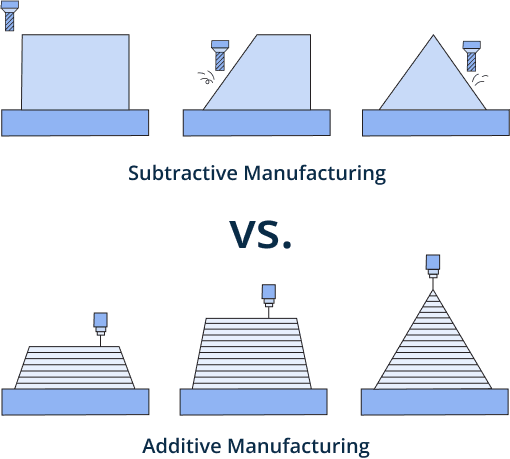
Diffrence Between Subtractive VS Additive Manufacturing
 |
|
|
|
Subtractive Manufacturing
In this process any object is cut or grated from a larger block or material and is given a new shape such that the machine starts cutting the object from the top and gradually the layer of that object will be reduced so that the correct shape can be made.Additive Manufacturing
In this process an object is built from bottom to top like one layer is added to another layer and this process continues until the final design is made.
Comprission sheet
 |
|
| Click here to download this Comprission in PDF formet |
Individual Assignment
3D Design
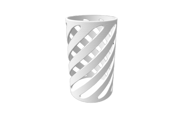
In the individual assignment, I first created a 3D design using Solidworks and downloaded it in STL file format.
.jpeg) |
.jpeg) |
| 3D designing in solid work |
Downloading design file in STL formet |
 |
|
| Final Design view after downloaded in STL formet |
Generateing G-Code for 3D printing
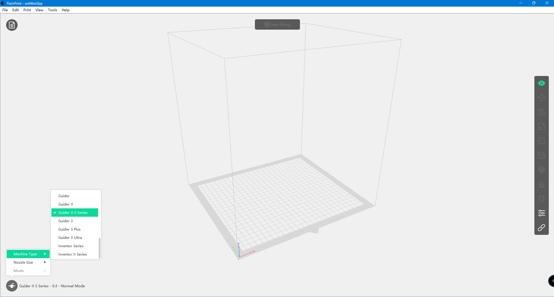
I used Flash-Print (FlaceforGe) software to generate g code and sliceing.
 |
|
| First, I opened the Flace Print software and then selected the printer. |
 |
|
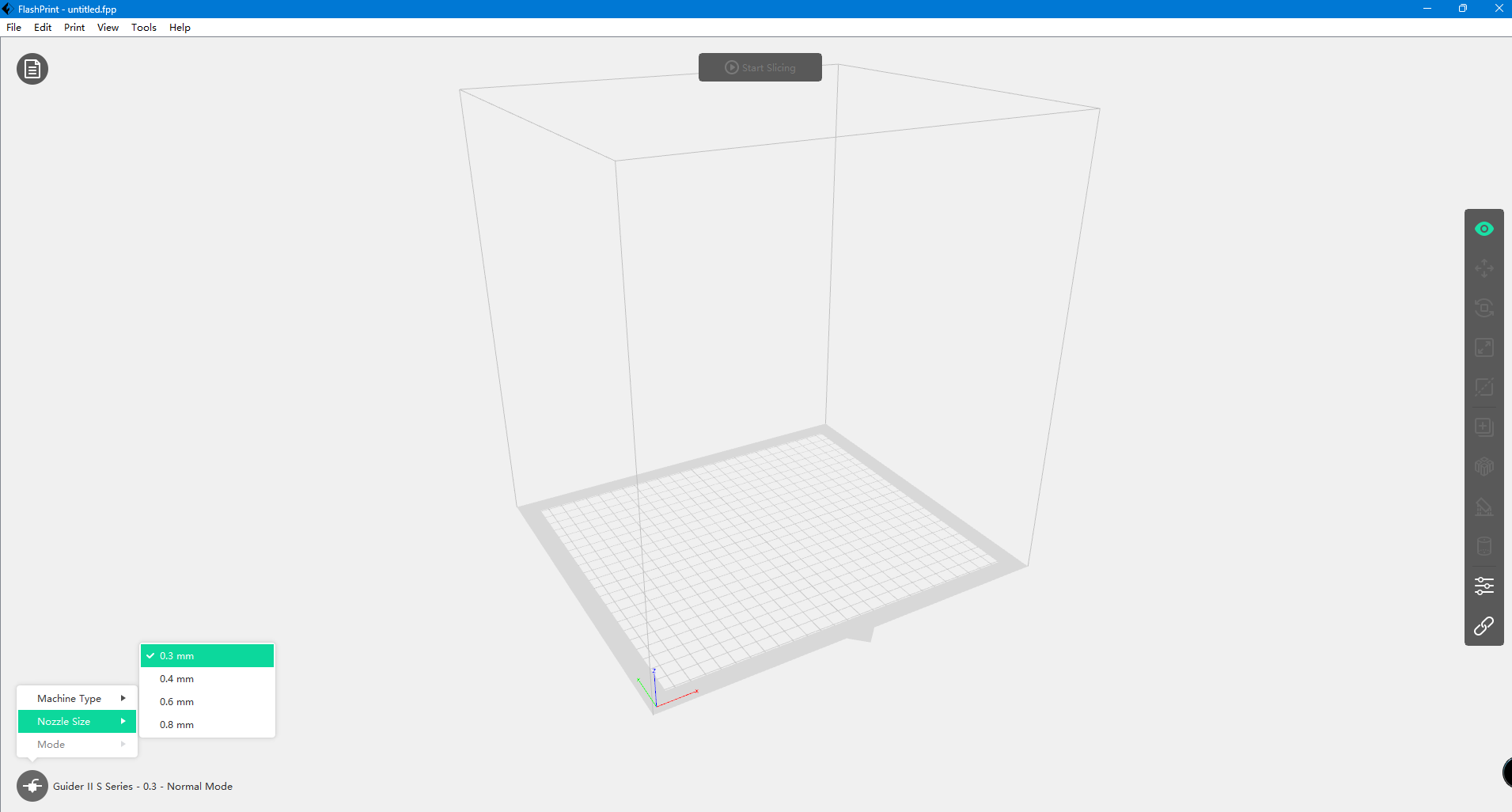
| Afterward, I set the nozzle size of the printer. |
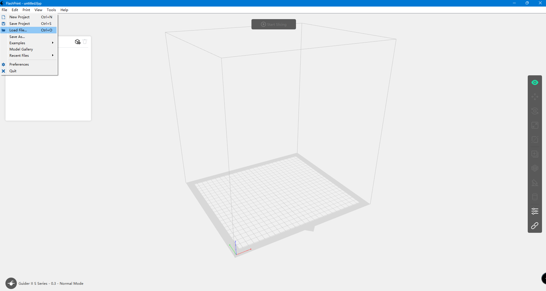 |
|
| Now loading the STL file into the software. |
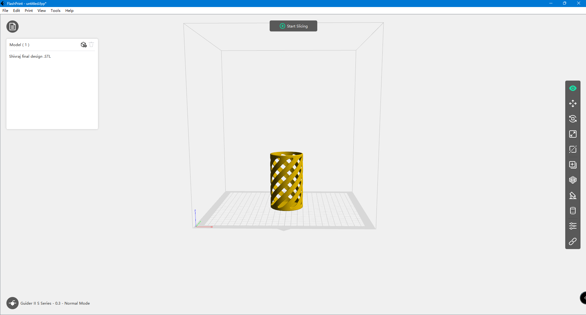 |
|
| The file successfully loaded into the software. |
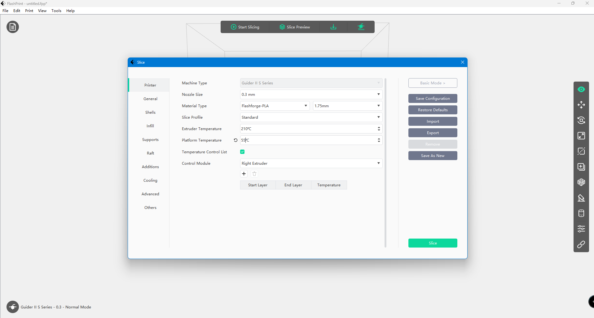 |
|
| Updateing the printing settings like Material type,Plateform temperature etc. After that, started to slice |
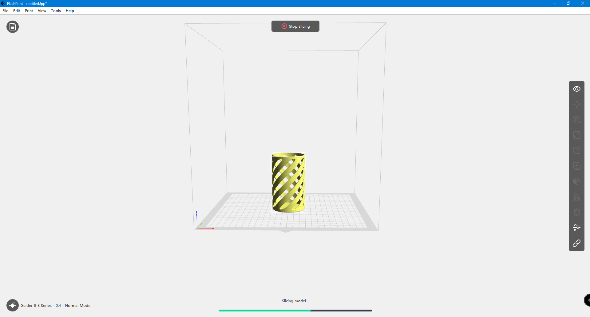 |
|
| Now the design in sliceing process |
 |
|
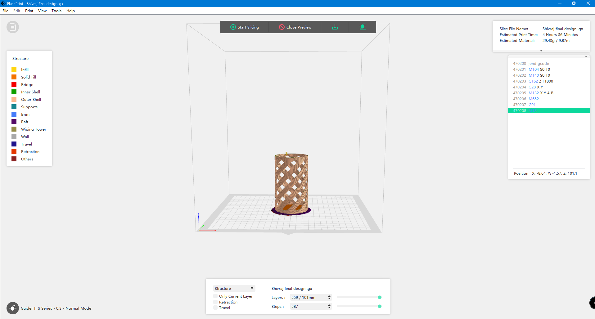
| After slicing, I previewed the design. |
 |
|
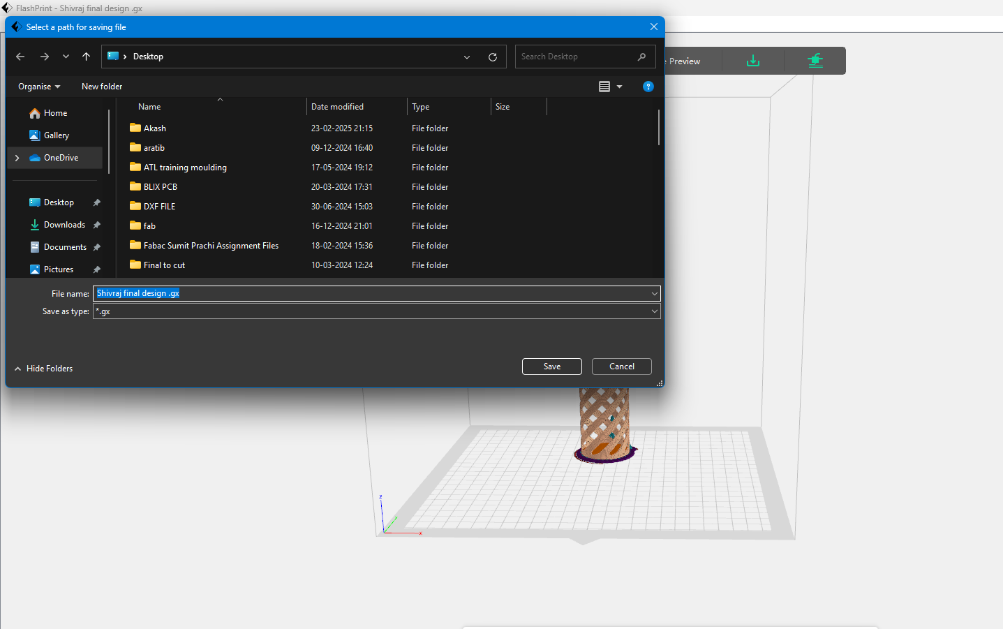
| Finally, I downloaded the design for final printing. The design file was downloaded in GX format. |
3D Printing
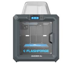
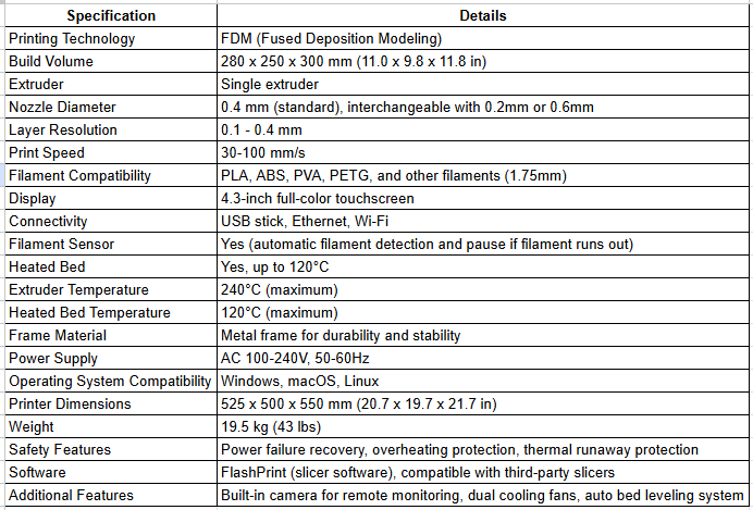
I used the Flashforge Guider IIs for 3D printing.
 |
 |
|
|
|
3D Design Printing Process
 |
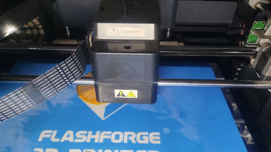 |
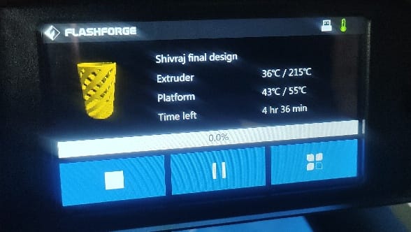
| Status of the design printing |
Design printing started |
 |
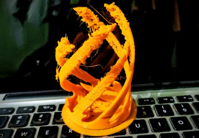 |
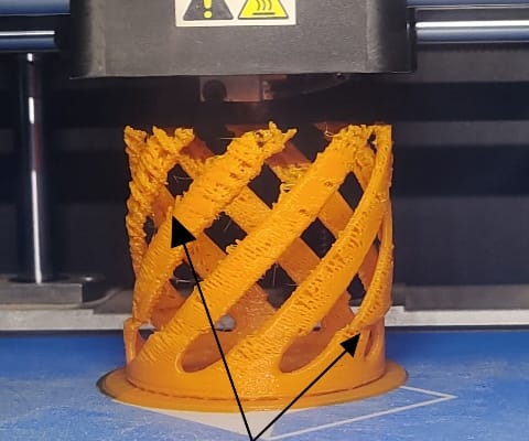
| The design wasn't printing properly, and the shape was getting distorted due to the pla material melting too much. |
After that, I had to stop the printer midway and remove the design. The design was completely spoiled. |
Observation
When I imported the STL file into FlashPrint software to generate the G-code, I noticed that no supports were added for the design. Additionally, the printer's nozzle size was set to 0.3 mm, while the default is 0.4 mm.
The platform temperature was set to 55°C, whereas it should have been 50°C. As a result, the combination of the high temperature and lack of supports caused the design to melt and lose its shape. I had to stop the print and remove the design from the printer.
Re- Process of 3D Design Printing
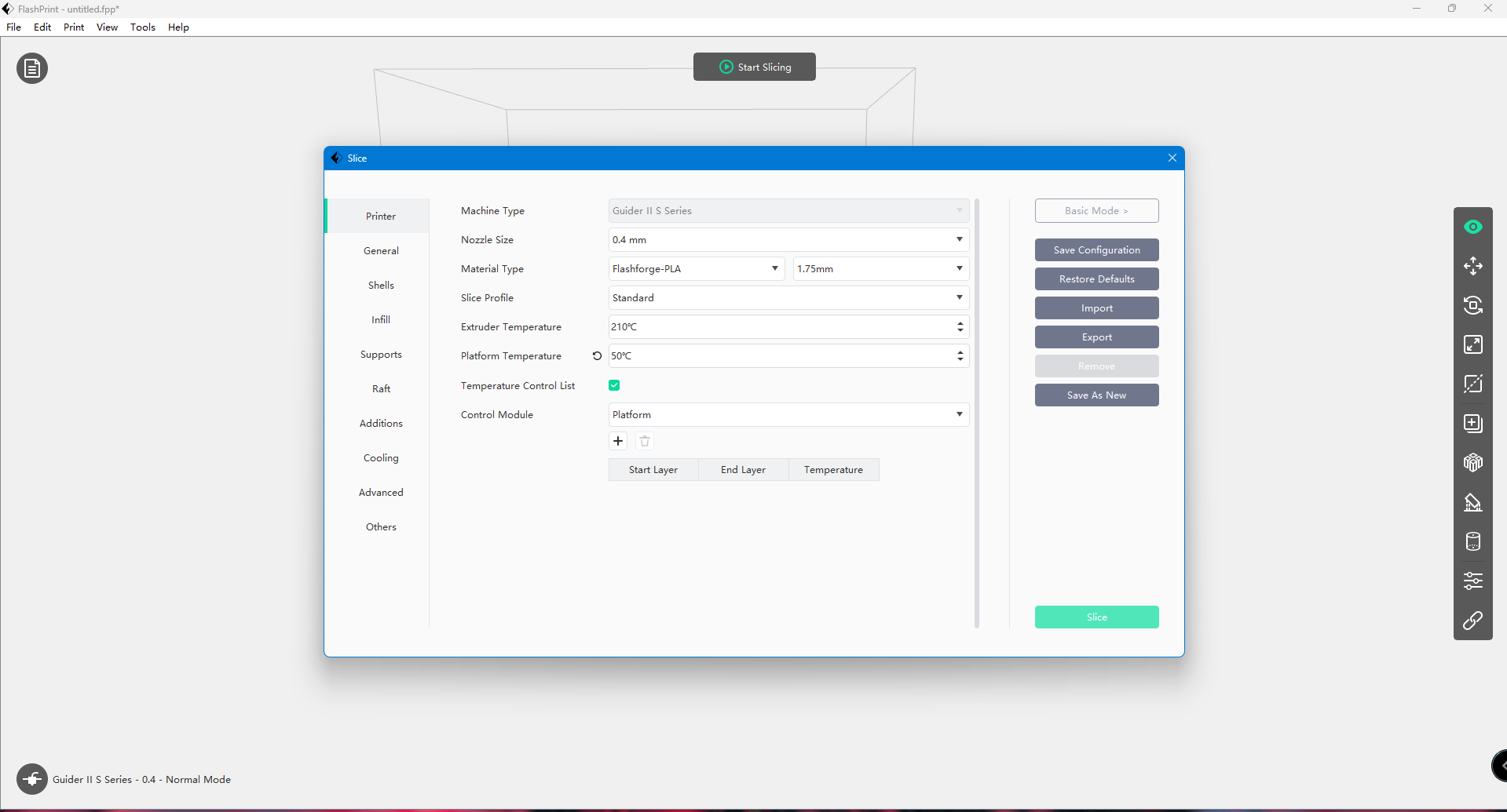
After the issues I observed with the previous print, I decided to restart the process, keeping the mistakes in mind I had made earlier. First, I make sure to set the nozzle size correctly to 0.4 mm, which is the default setting for the printer, rather than the 0.3 mm that was mistakenly used before. I also adjusted the platform temperature to the correct setting of 50°C, as it should be, instead of the higher 55°C I had used previously.
The original design was set at a size of 100 mm, which resulted in a longer estimated print time of 4 hours and 36 minutes. To make the process more efficient, I reduced the size of the design, which helped decrease the estimated print time significantly.
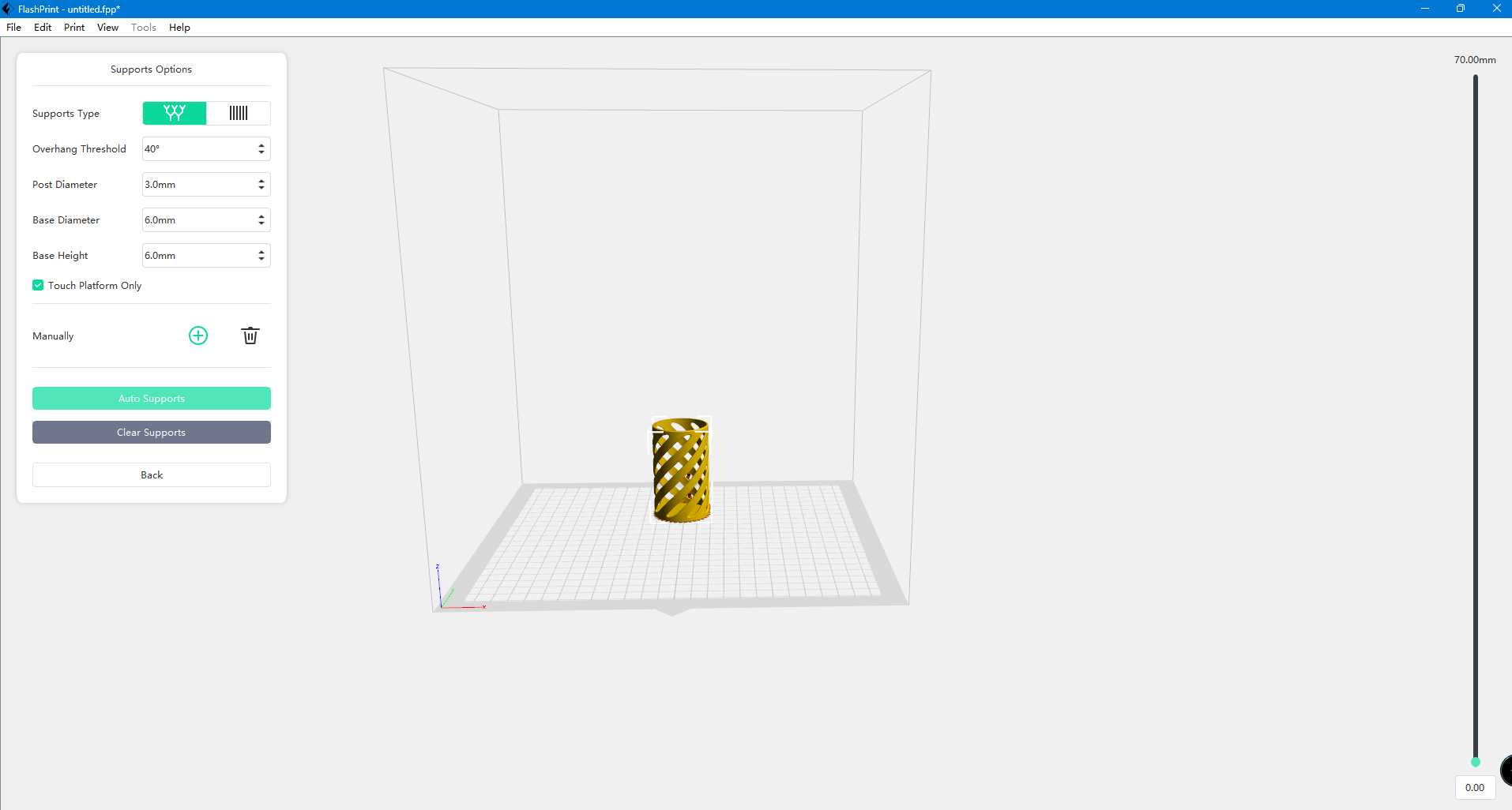
Finally, I added supports to the design. This was crucial to ensure that the print would remain stable and aligned throughout the process, helping the design maintain its correct shape and direction until it was fully printed.
 |
 |
| This time, I added auto support for the design. |
I set the nozzle size to 0.4 mm and the platform temperature to 50°C. |
 |
 |
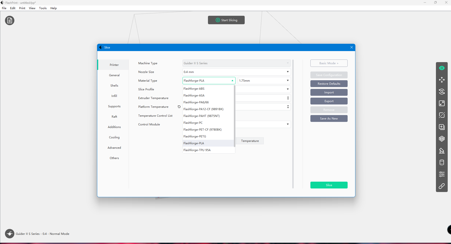
| Selected the material and started the slicing process. |
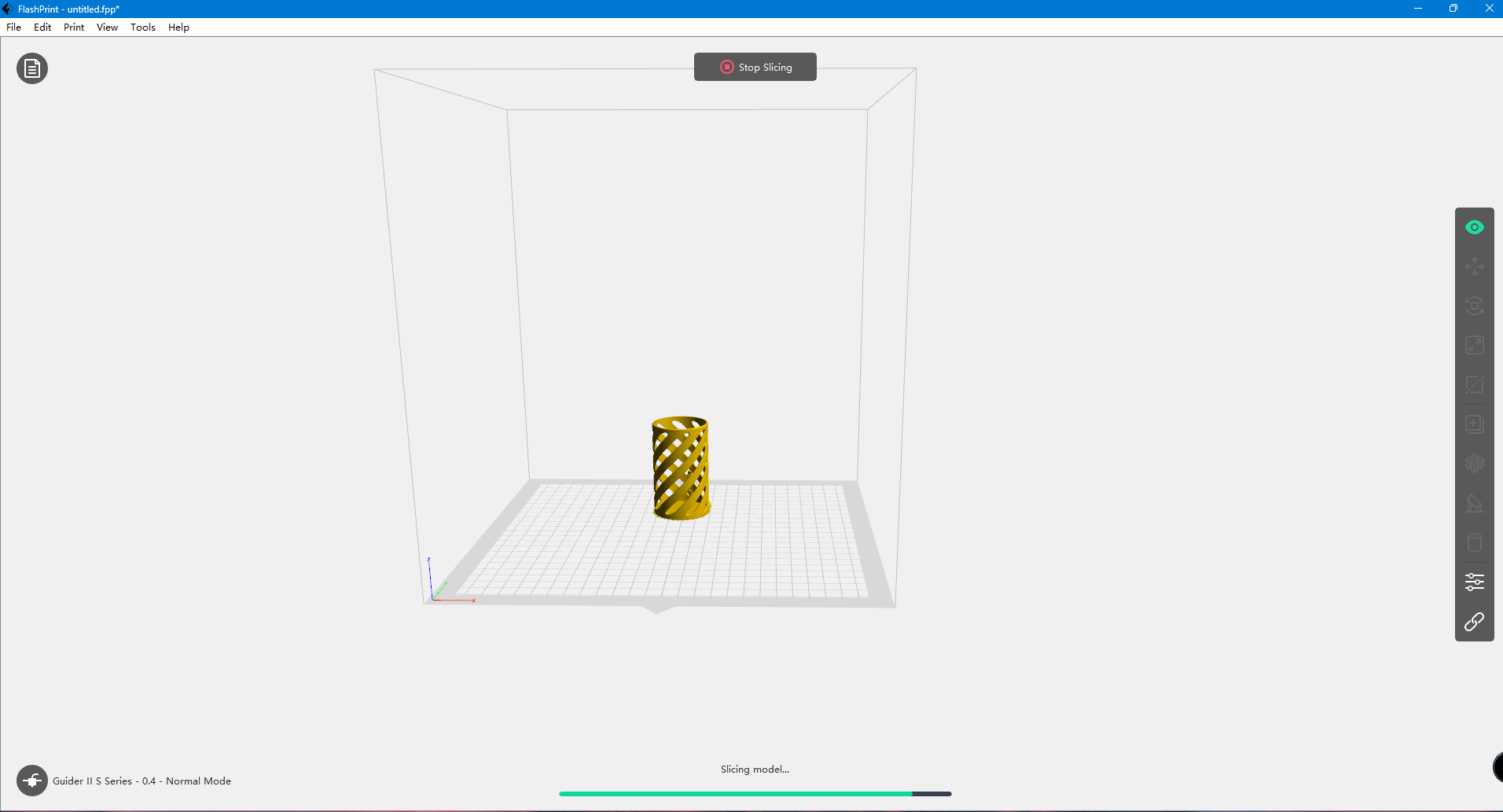
Now the design in sliceing process |
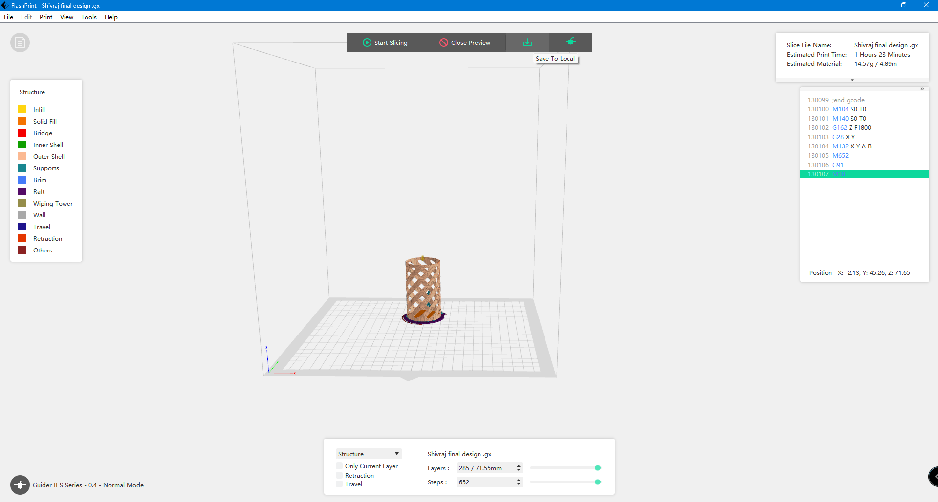 |
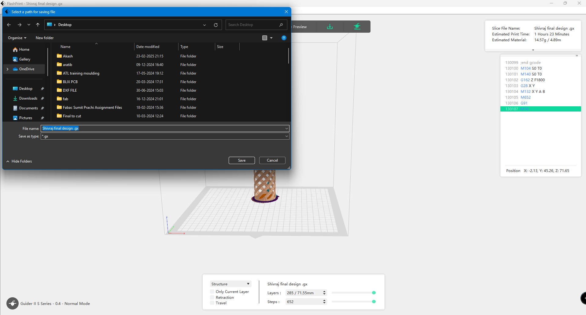 |
| After slicing, I previewed the design. |
Downloaded the design for final printing. The design file was downloaded in GX format. |
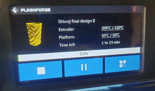 |
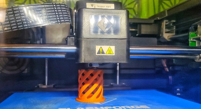 |
| Started design printing |
During the printing, I checked the design, and this time, the design is printing correctly. |
 |
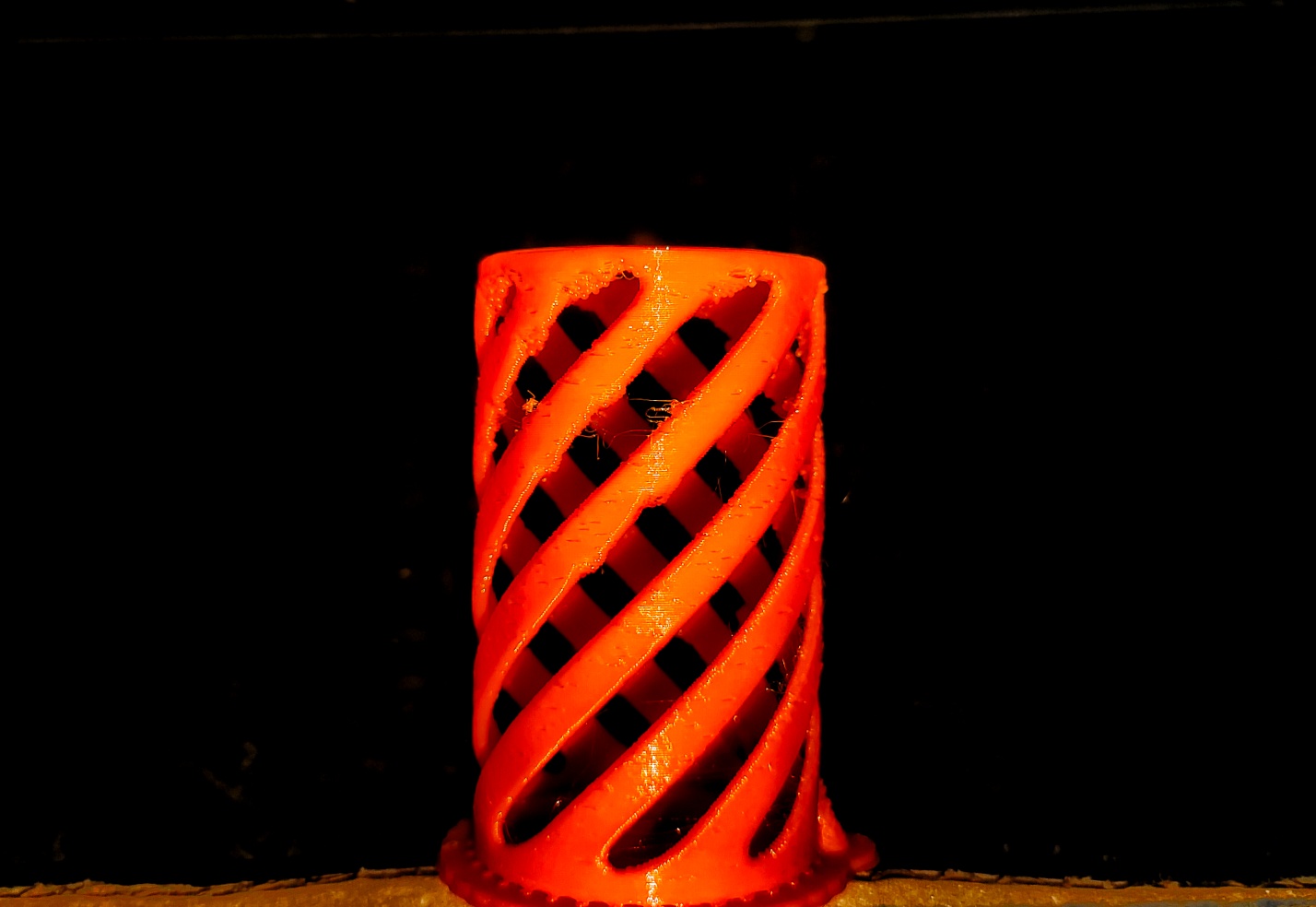 |
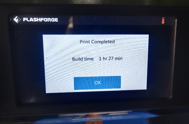
| The design is showing as complete print on the screen. |
Finally, the design was complete, and I removed it from the printer. |
Parameters of the Design
3D scanning and Photogrammetry to create model using Sense scanner (1st Gen)
 |
 |
|
|
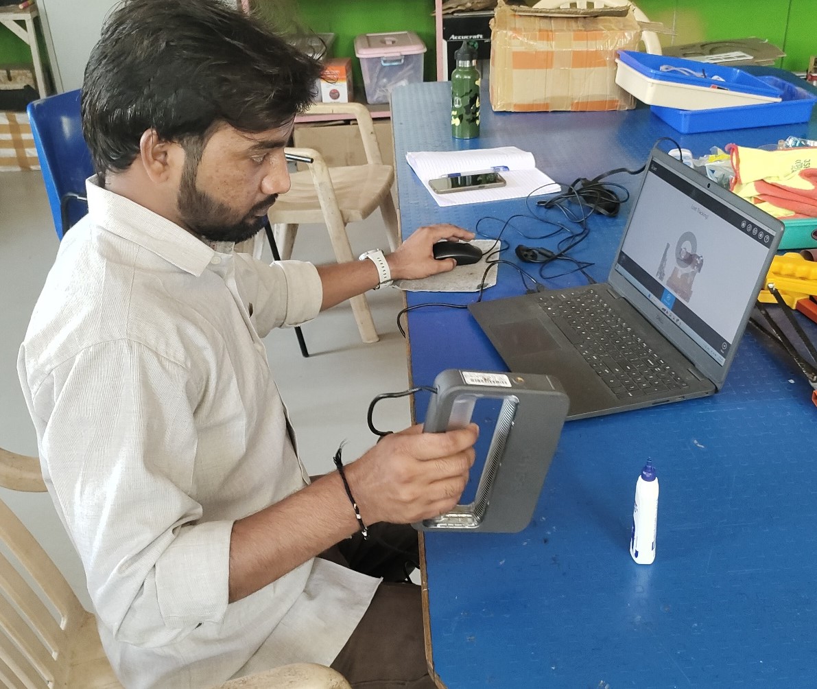
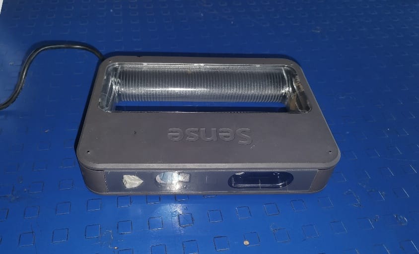
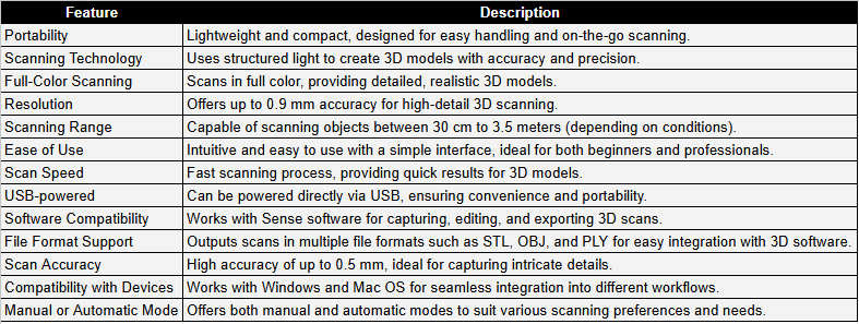
I used the Sense scanner (1st Gen) for 3D scanning. The Sense Scanner is a portable 3D scanner that allows users to capture detailed 3D models of objects and environments quickly and easily.
Sense Scanner Key Features
 |
|
| Click here to download PDF formet of Key Features |
Scanning Process
 |
 |
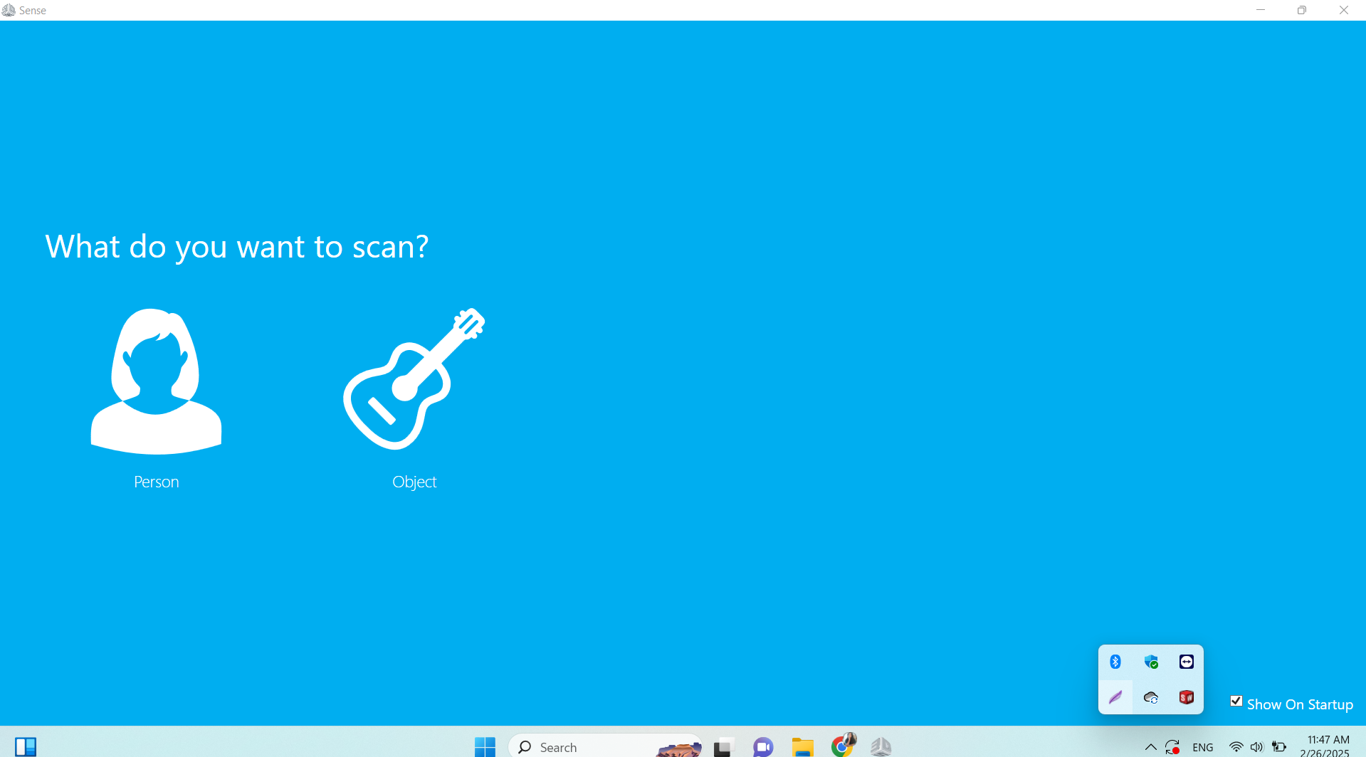
| First, I opened the Sense software and selected the person. |
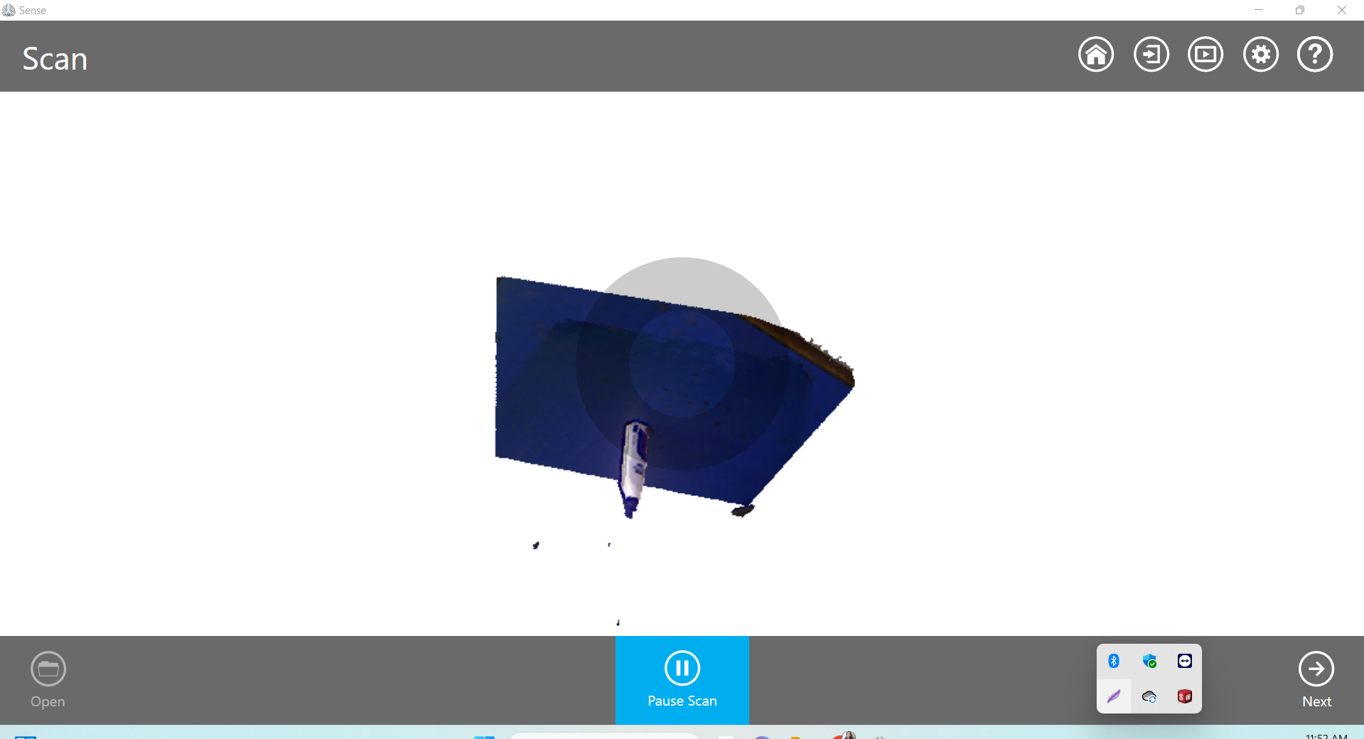
For practice, I started by scanning a small object first. |
 |
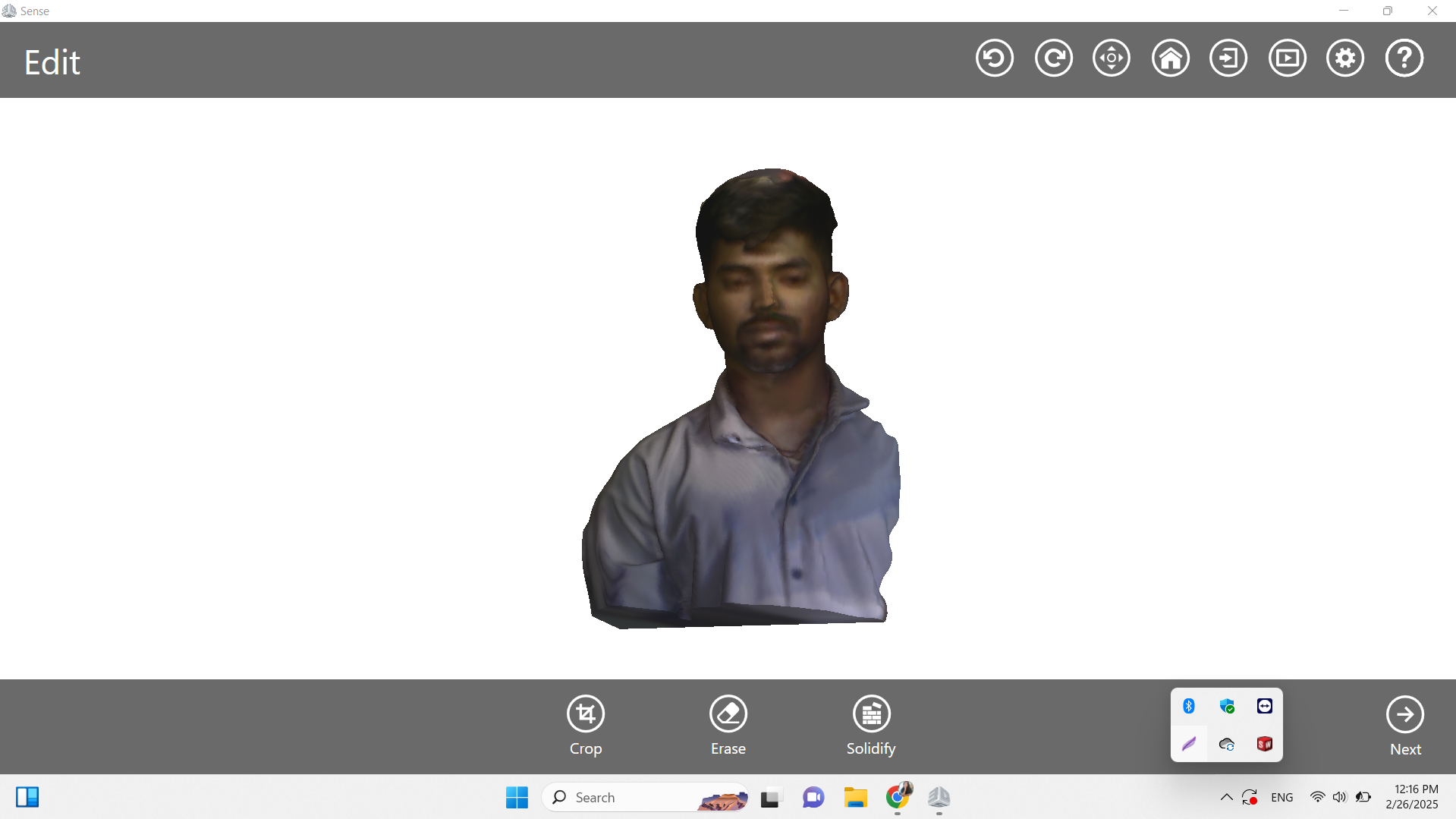 |
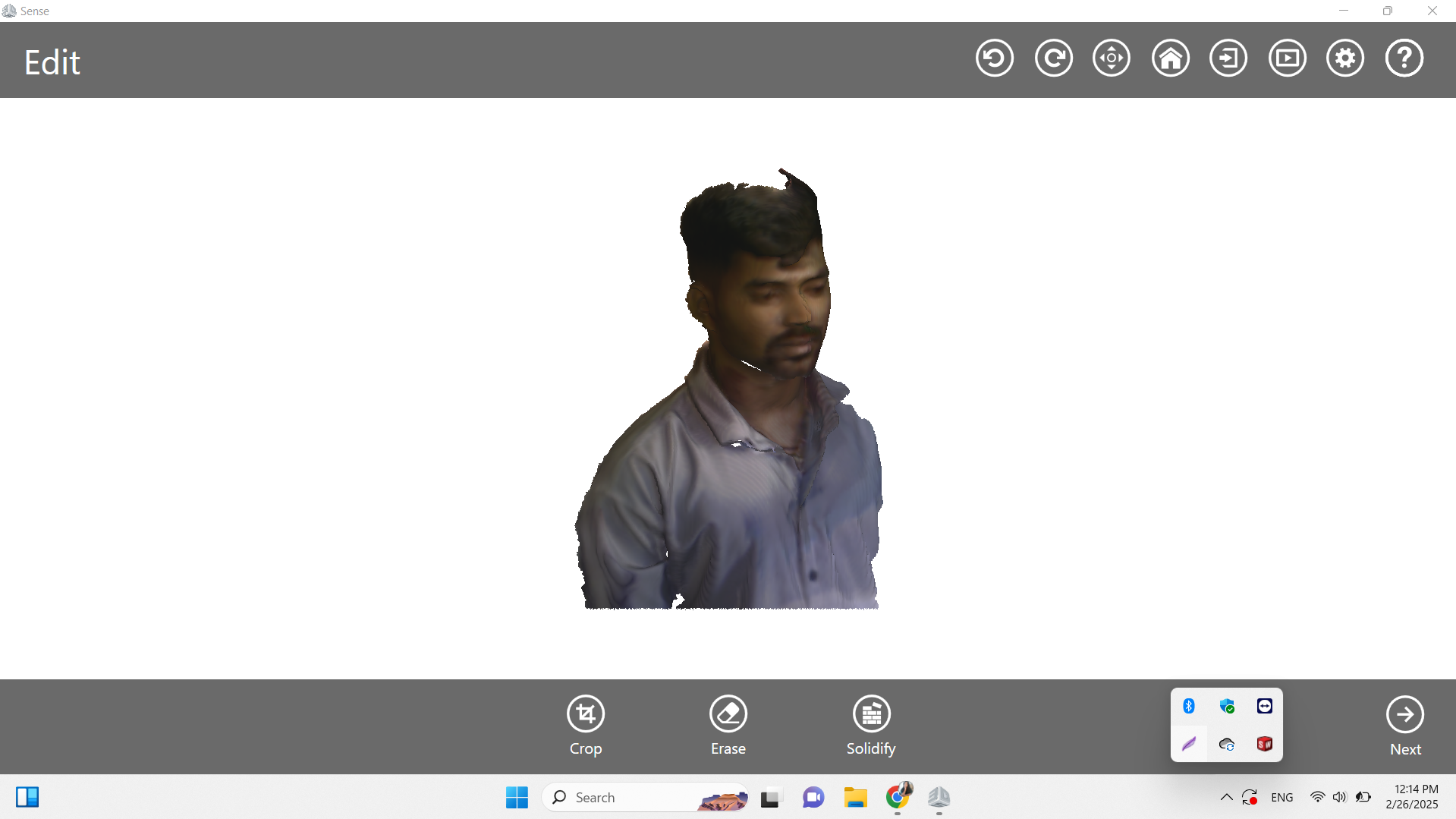
| After that, I scanned the person. |
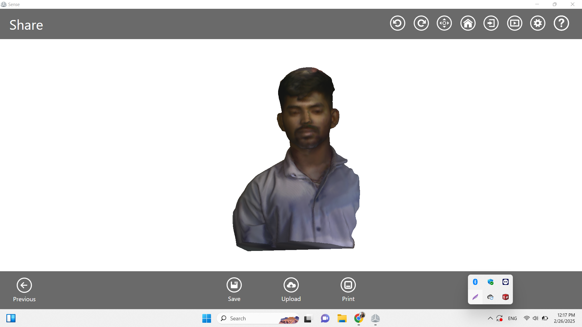
Scanned the person from all sides.And I clicked on the solidify option, which fixed the parts that were missing or cut off. |
 |
|
| Finally, I clicked on the save option to download the scanned file, and it was downloaded in STL format. |
|
In addition to the Sense Scanner, I also explored the "WIDAR" app for 3D scanning.This app is available on the Play Store and has a rating of 4.6
 |
|
|
|
 |
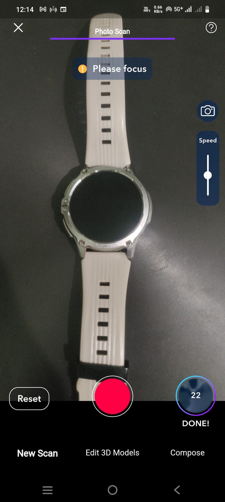 |
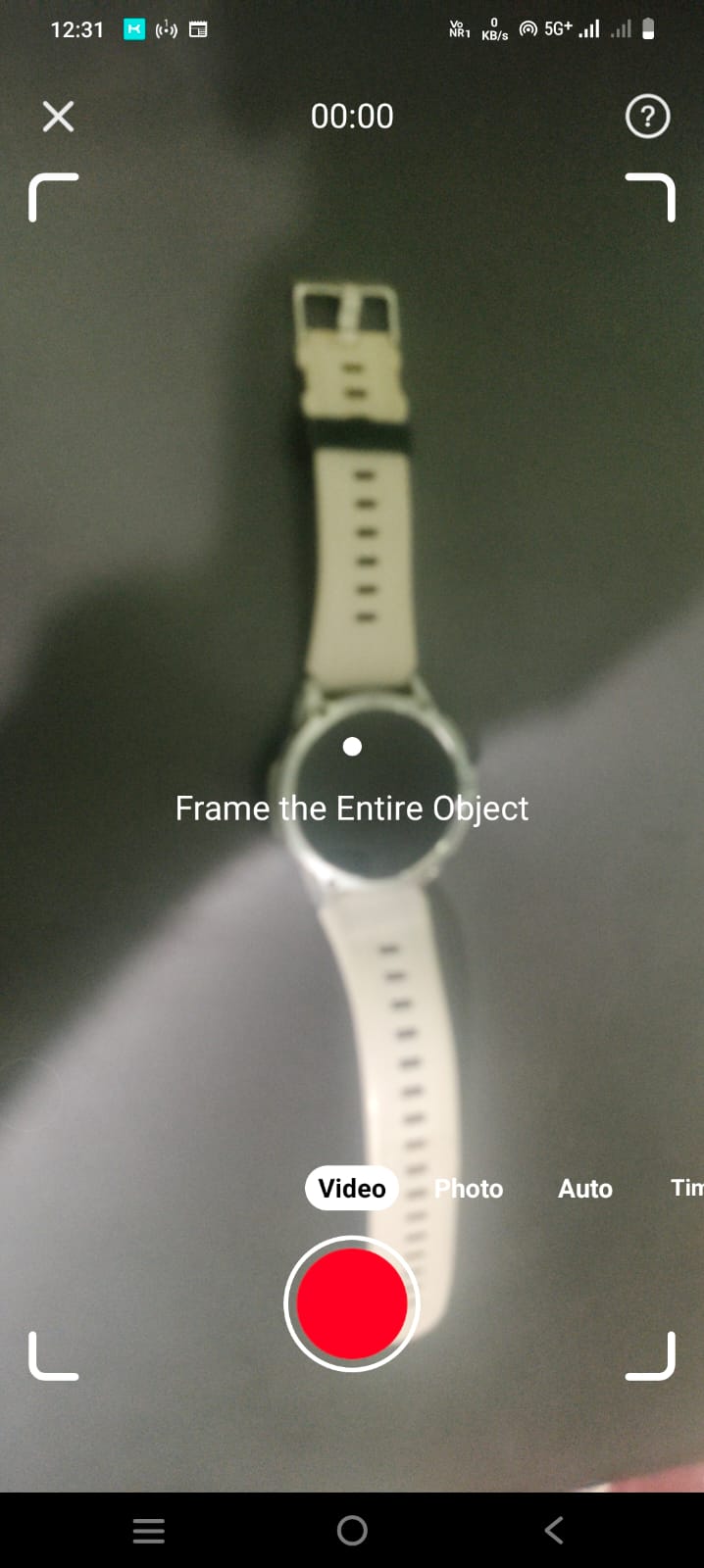
| First, I opened the WIDAR app on my phone and framed the object. |
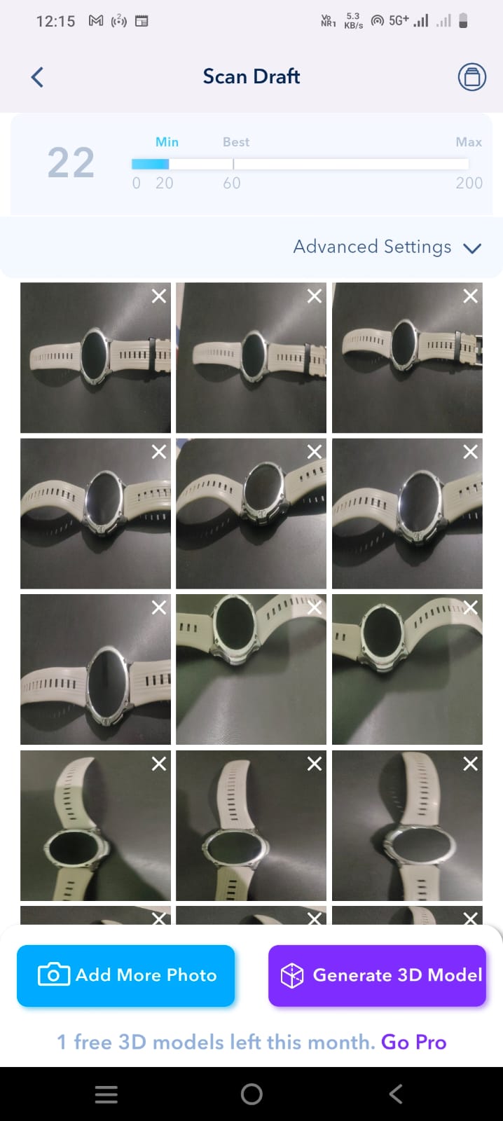
I started scanning the framed object by rotating the camera around it from all sides. And clicked on Done option. |
 |
 |
| After this, I clicked on the option to generate a 3D model of the scanned object. |
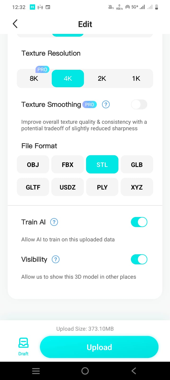
After that, I selected the STL format in the settings. |
 |
 |
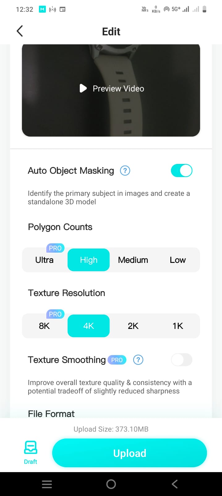
| After that, I turned on the auto object masking option in the settings and set the texture resolution to 4K. And clicked on upload option. |
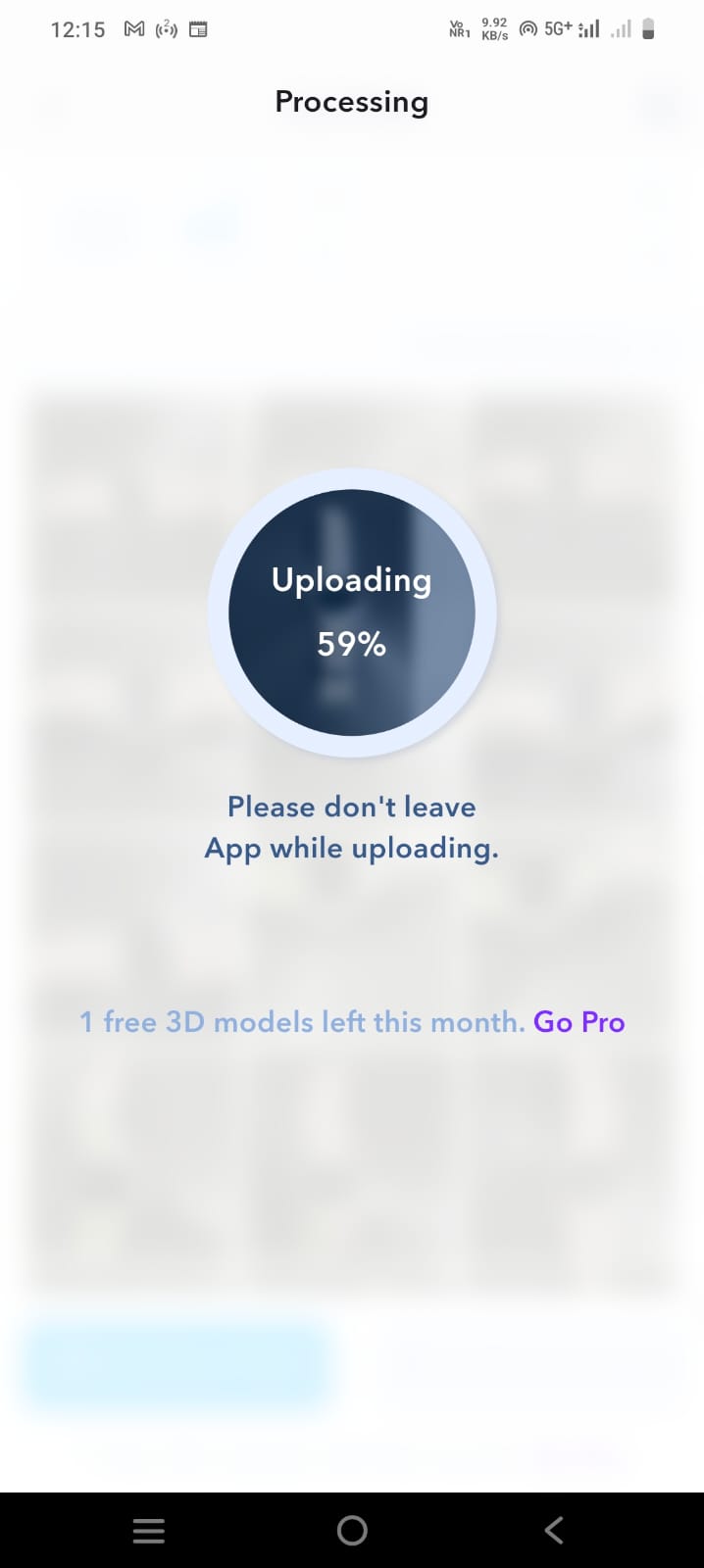
The scanned video started uploading. |
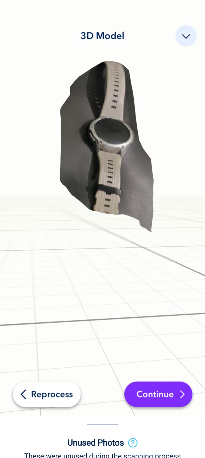 |
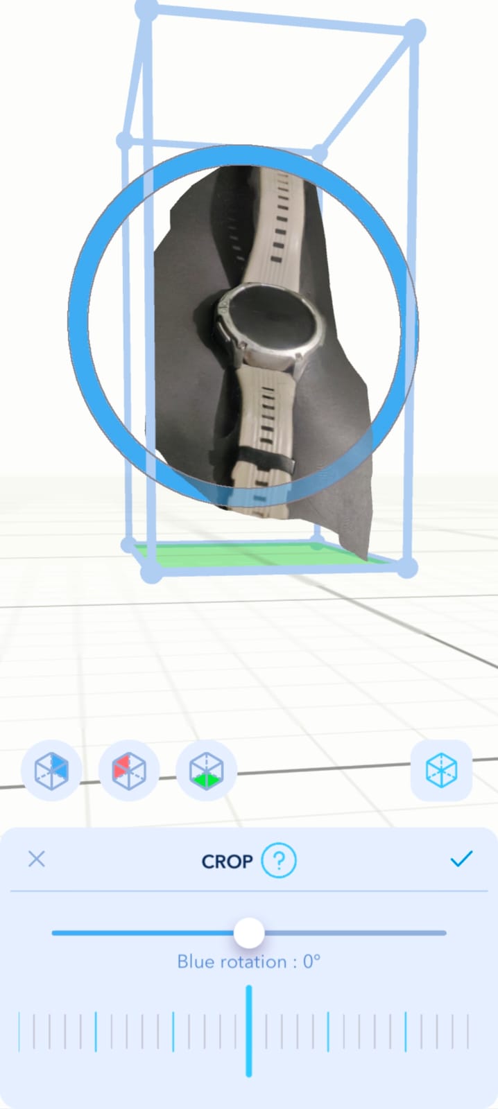 |
| After that, a 3D shape was created. |
Then i set it for CROPING. |
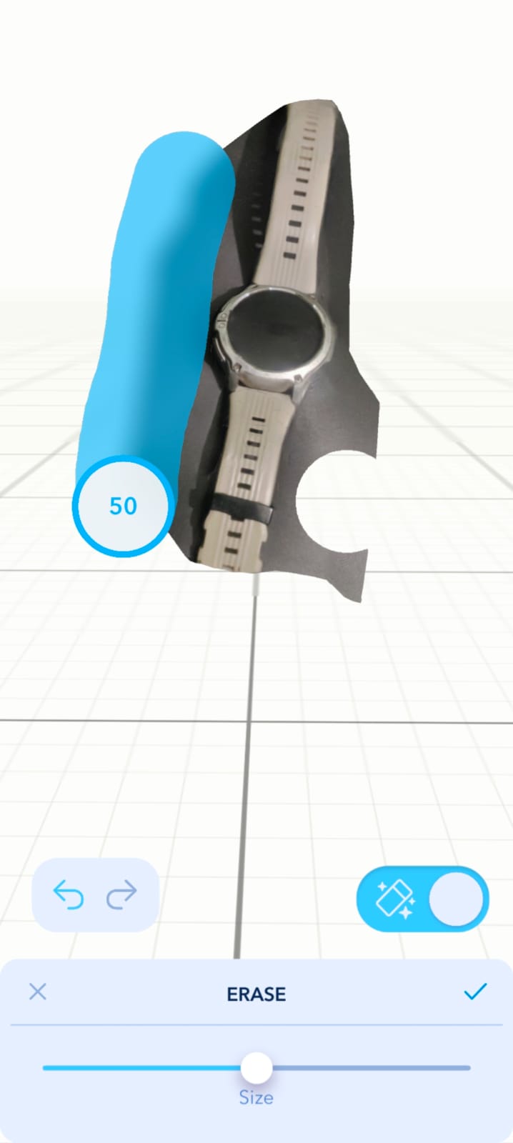 |
 |
| After that, I removed the unwanted part. |
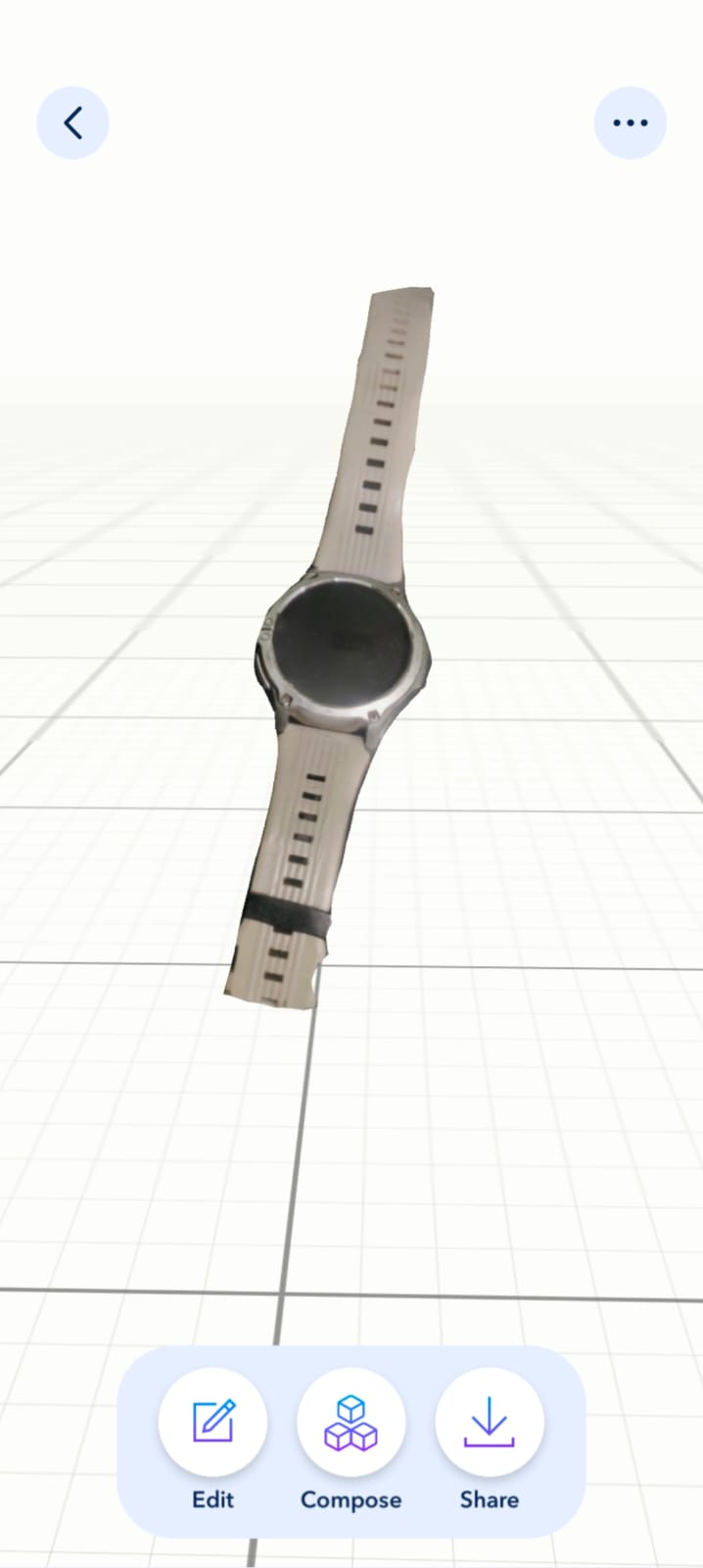
Finally, the object's final shape was ready. |
Tools I used for this Assignments
Download Original File's
Download 3D design file in STL formet here
Download 3D scaning file in STL formet here