Computer-Controlled Machining
Learning Experience
This week, I delved into the realm of computer-controlled machining by utilizing SolidWorks and Fusion 360 to design intricate 3D models. These models were then processed through VCarve Pro, where I converted them into G-code suitable for CNC wood routing. In addition to ensuring that all machining procedures were carried out safely and efficiently, I gained hands-on experience with machine operation, toolpath creation, and the advanced techniques involved in digital fabrication. This practical exposure not only enhanced my technical skills but also deepened my understanding of the machining process from design to execution.
Key Accomplishments
✅ Created 3D models for CNC milling with SolidWorks and Fusion 360.
✅ Accurate machining was achieved by using VCarve Pro to generate exact G-code.
✅ Successfully finished the safety training for wood routers and used the CNC machine.
✅ Improved abilities in digital fabrication, such as the development of toolpaths and machining methods.
Task: Electronics Design
Group assignment:
Use the test equipment in your lab to observe the operation of a microcontroller circuit board
Demonstrate the use of a multimeter and oscilloscope
Document your work on the group work page and reflect on your individual page
Individual assignment:
Use an EDA tool to design a development board
Ensure the design uses parts from the inventory to interact and communicate with an embedded microcontroller
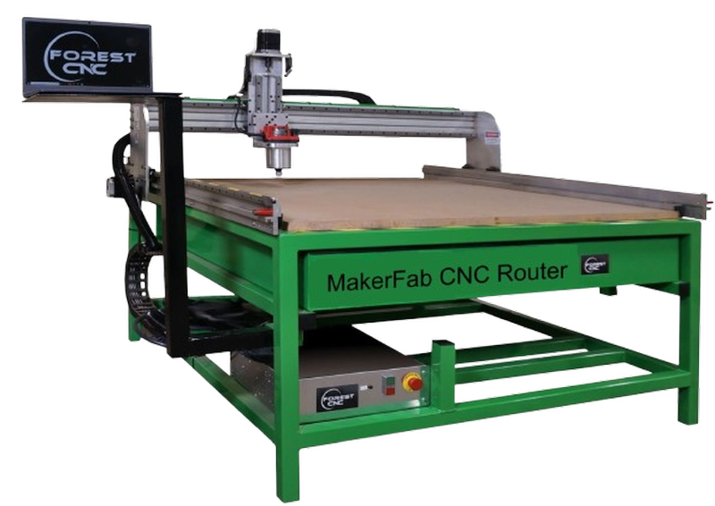
Forest CNC Router:
The Forest CNC Router is a sophisticated computer-controlled machine designed for precise cutting, engraving, and shaping of various materials. It is capable of working with light metals, composites, wood, and plastic, offering versatility across multiple applications. This advanced tool is primarily used in industries such as fabrication, prototyping, signage creation, furniture manufacturing, and various industrial processes, enabling high-quality and efficient production.
Key Features
Accurate and clean cuts are guaranteed by precise cutting.
Supports Multiple equipment: It is compatible with a wide range of engraving and cutting equipment.
Computer programming is used to control automated operations.
Supports wood, MDF, acrylic, PVC, aluminium, and other materials.
Control the speed and feed according to the depth of cutting and the material.
Big Workspace: Ideal for both little and major tasks.
Safety features include a dust extraction system, spindle control, and emergency stop.
Specifications
| Category |
Specification |
Details |
| Construction and Frame |
Material |
Steel or cast iron |
| Size |
Table sizes range from 2’×3’ to 5’×10’ or more |
| Spindle |
Power |
2.2 kW to 12 kW |
| Speed |
6,000 to 24,000 RPM |
| Cooling |
Air-cooled or water-cooled |
| Axes |
Number of Axes |
3-axis (X, Y, Z) |
| Movement |
Ball screws or rack and pinion |
| Resolution |
Down to 0.01 mm or better |
| Controller |
Type |
Dedicated CNC or PC-based controllers |
| Software Compatibility |
AutoCAD, SolidWorks, VCarve, etc. |
| User Interface |
Touch screen or handheld pendant |
| Cutting Area |
Dimensions |
Common sizes are 4’×8’ or custom sizes |
| Z-Axis Travel |
0 inches to 12 inches |
Types of End Mills
| End Mill Type |
Image |
Description |
| Square End Mills |
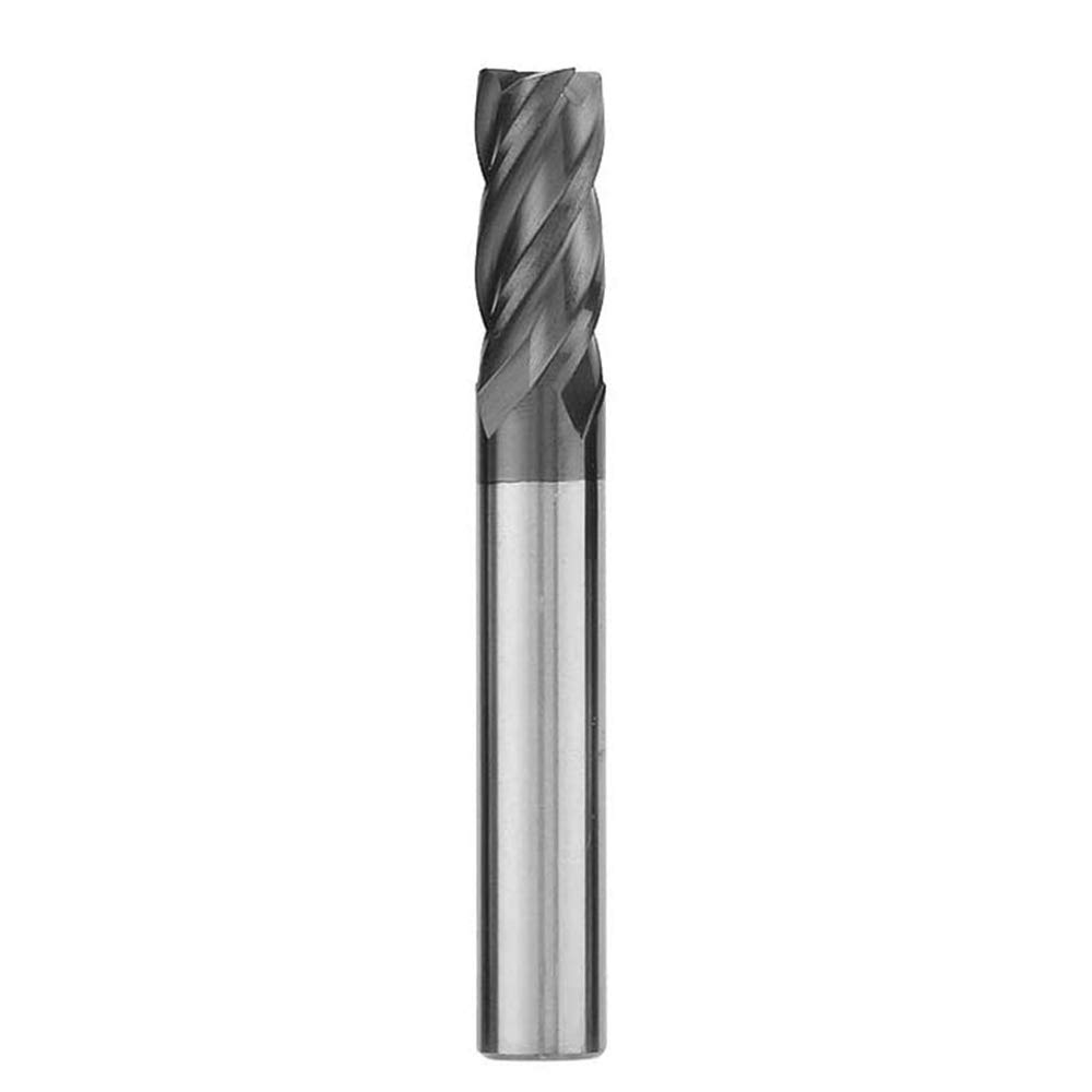 |
Square end mills are commonly utilized for making straight cuts, creating slots, and finishing surfaces, characterized by their flat cutting end. |
| Keyway End Mills |
 |
These mills are specially designed to cut key-shaped slots in metal components, often used to accommodate woodruff keys or other inserts. |
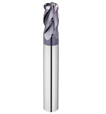
| Ball End Mills |
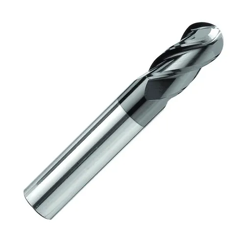 |
Ball end mills are ideal for creating contoured, 3D shapes and curved features due to their rounded tip, making them suitable for precision machining. |
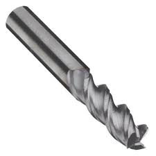
| Roughing End Mills |
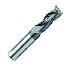 |
Roughing end mills are engineered for efficient material removal at a high rate, minimizing chatter due to their unique tooth geometry, ideal for heavy-duty cutting. |
| Corner Radius End Mills |
 |
These tools feature a small radius at the corners, which not only helps to avoid chipping but also enhances the tool's strength and durability during cutting. |
| Roughing and Finishing End Mills |
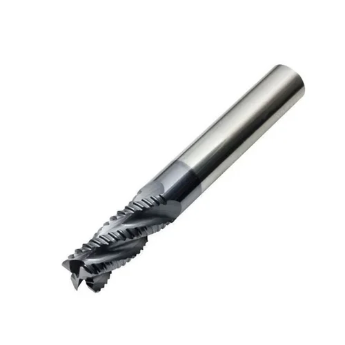 |
Roughing and finishing end mills combine two functions in one tool, capable of performing both rough cuts and fine finishes, offering significant time and effort savings. |
| Corner Rounding End Mills |
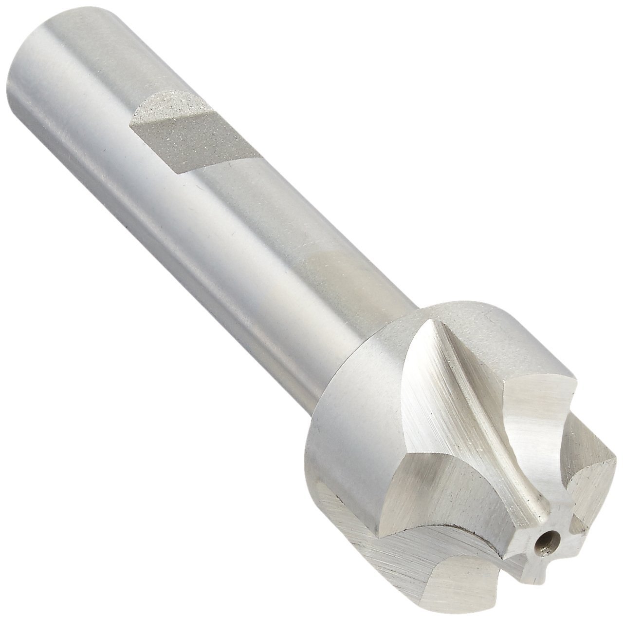 |
Corner rounding end mills are ideal for creating smooth, rounded edges on parts, ensuring a polished finish and reducing the likelihood of damage or wear. |
| Drill Mills |
 |
Drill mills are versatile tools that can perform a variety of tasks such as drilling, chamfering, milling, and light profiling, making them essential in multi-purpose machining setups. |
| Tapered End Mills |
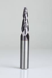 |
Tapered end mills feature a conical shape that tapers toward the tip, making them perfect for applications such as mold making and cutting angled surfaces. |
Flute Types and End Cut Types
| Flute Type |
Image |
Description |
| Single Flute |
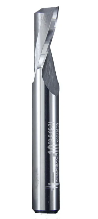 |
Single flute end mills are well-suited for rapid cutting, especially when working with soft materials, due to their large chip clearance that ensures smooth operation. |
| Two Flute |
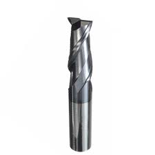 |
Two flute end mills are commonly used for slotting operations, offering good chip ejection and a balance between cutting speed and stability. |
| Three Flute |
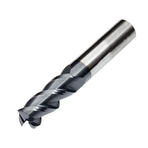 |
Three flute end mills provide an optimal balance between cutting strength and chip removal efficiency, making them ideal for shallow cavity work. |
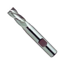
| Four/Multiple Flute |
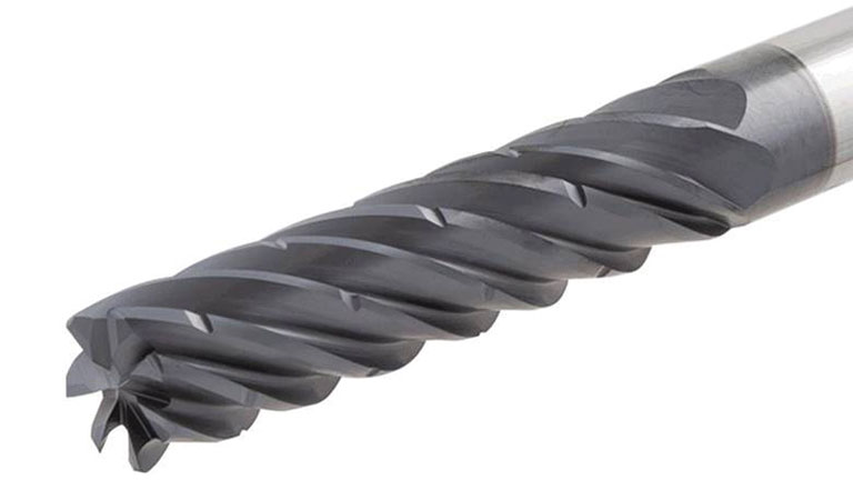 |
End mills with four or more flutes provide smoother finishes and can handle faster feed rates. However, they have limited space for chip removal, which may affect performance in certain materials. |
For both our group and individual assignments, we used a 6 mm end mill paired with a 6 mm collet. This tool is robust and highly reliable, delivering excellent performance when cutting MDF material. It also provides a 6 mm kerf, ensuring precise and efficient cuts with minimal effort.
Design Process
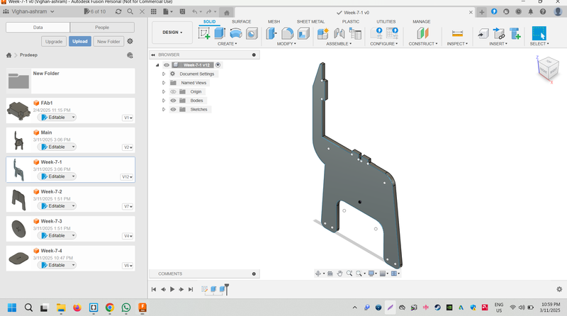
My initial concept was to design a study table that would provide students with a comfortable and ergonomic space to sit and study while maintaining a straight posture. I aimed to create a design that would ensure ease of use for prolonged study sessions. Using Fusion 360, I brought this idea to life by designing a study table that fulfills these needs.
In Fusion 360, I created four individual parts and then assembled them into the final design:
Part 1
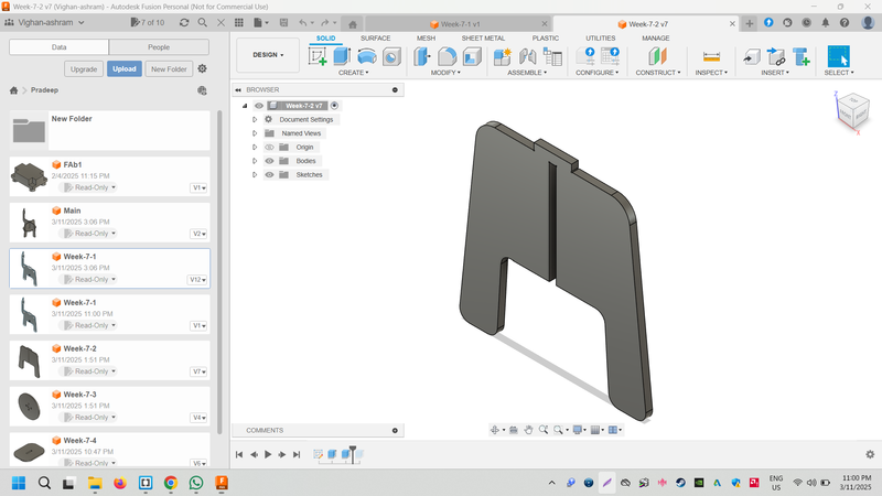
Part 2
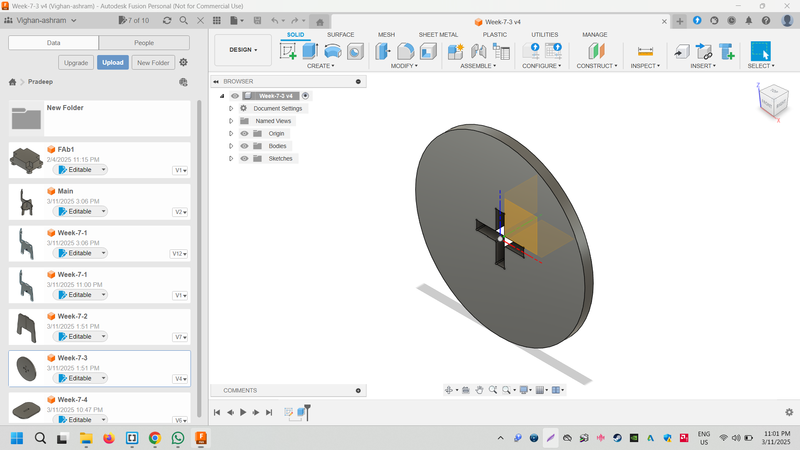
Part 3
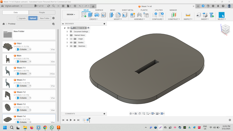
Part 4
Assembly Process
All the design files are saved in the DFx file format.
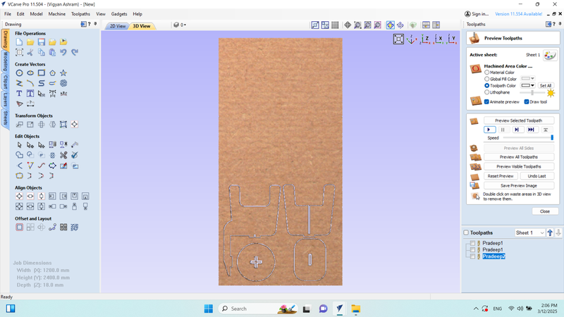
Creating Toolpath with VCarve
VCarve is a versatile CAM software that seamlessly integrates with plywood and StairDesigner, supporting a wide variety of CNC machines. It offers an array of design and manufacturing features, including carving, engraving, moulding, sign making, nesting, and more.
The image below illustrates the parts from a PolyBoard project, nested within VCarve. It displays the full toolpaths, ready to be output to a CNC machine.
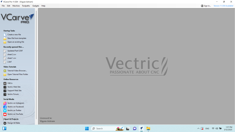
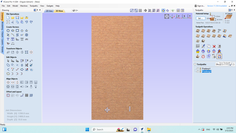
Initially, we launched VCarve software and selected the "Create a New File" option to begin the setup.
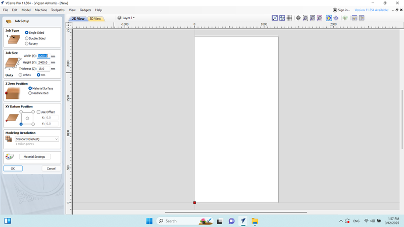
Next, we configured the job setup for an 8/4 plywood with a 12 mm thickness and adjusted the X-Y position as required.
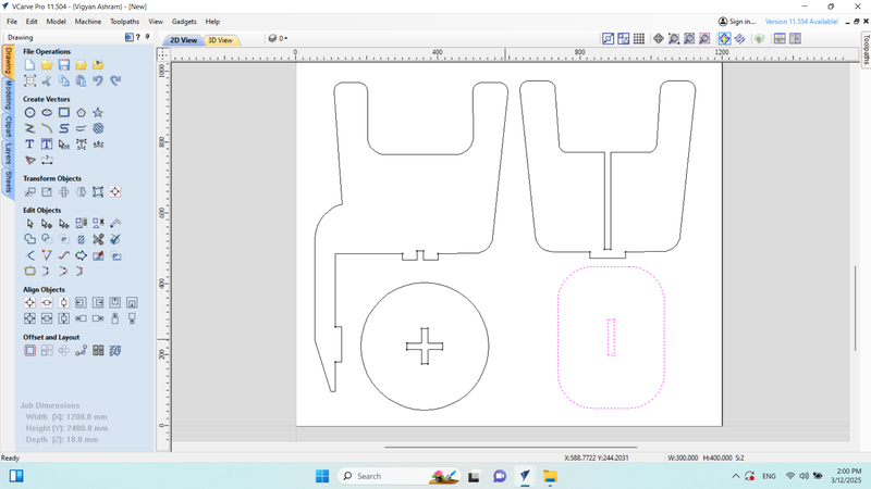
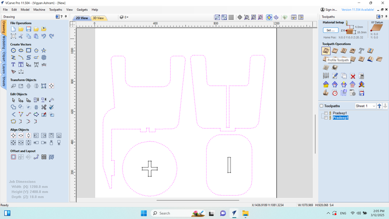
Then, we clicked on the "Toolpath" option to proceed with creating the toolpaths.
Afterward, I selected the desired size for the cutting area and chose the "Profile Toolpath" option. I proceeded to configure the profile and calculated the toolpath file.
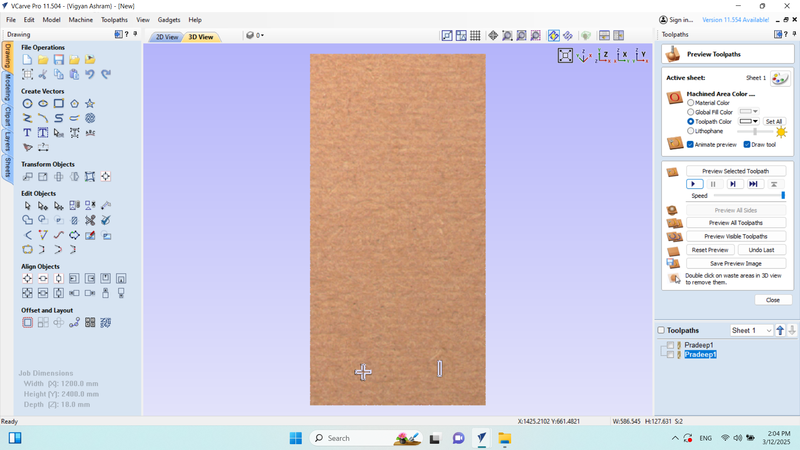
I ran a simulation to verify that the design was being cut correctly and adjusted if necessary.
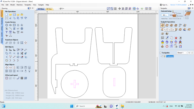
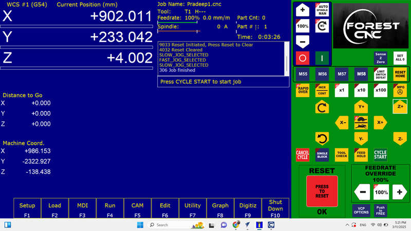
Next, I clicked on the "Save Toolpath" option to save the configuration.
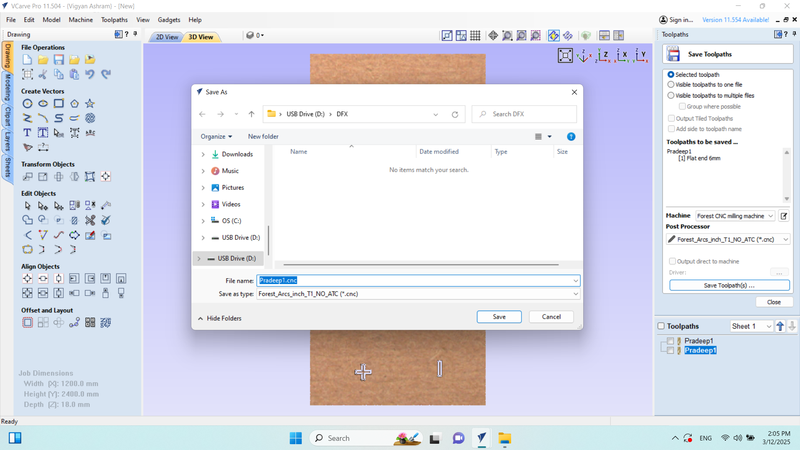
The file was saved as "Pradeep1.CNC".
Then, I selected the outer design and clicked on "Profile Toolpath" again.
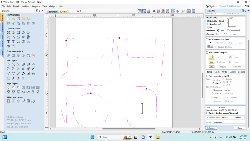
I generated the toolpath and clicked on "Calculate" to proceed.
I ran another simulation to ensure the design was correctly cut.
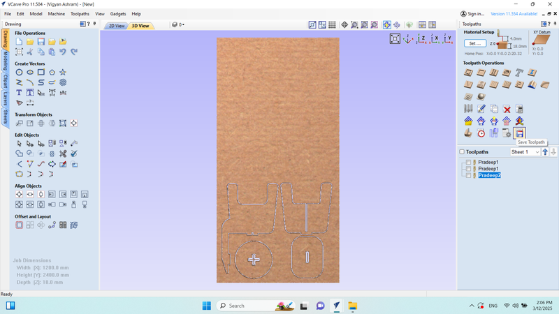
Next, I clicked on "Save Toolpath" once more.
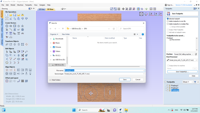
The file was saved as "Pradeep2.CNC".
Loading the File For the Cutting
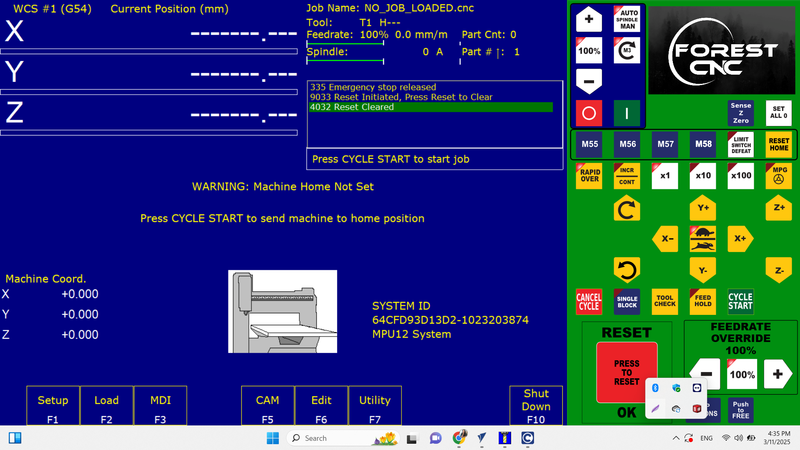
Connected the RJ45 connector to the laptop, turned on the machine, and opened the Acorn software.

The axis XYZ was set up at home, and then it was brought back to its original location.
Loaded the inside file and cut it,

Loaded the outside file and cut it,
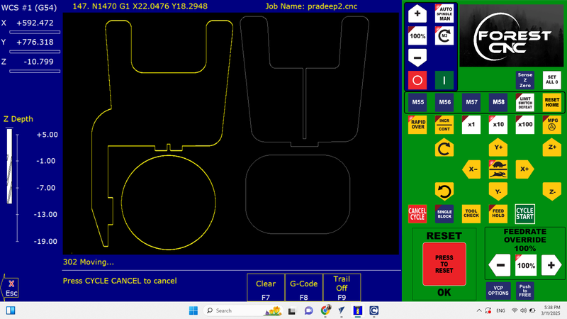
When the file is cut, a graph is generated that shows how many millimeters the end mill is cutting into the material.
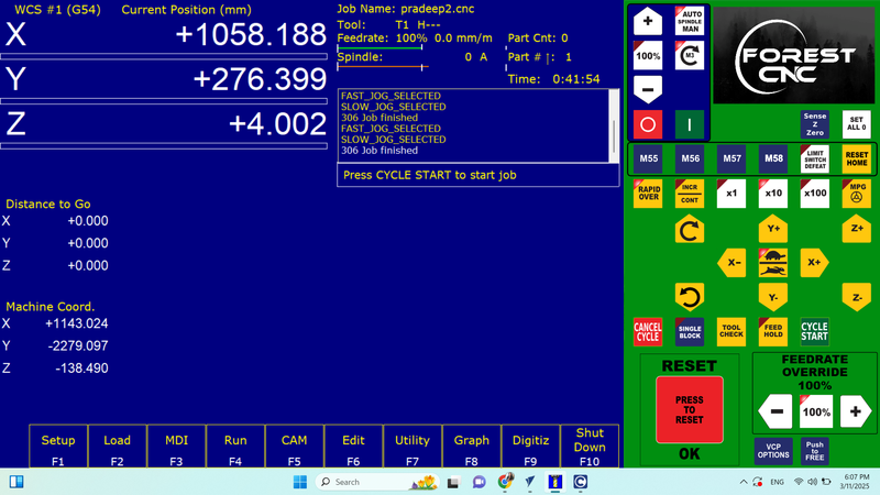
Job Finished.
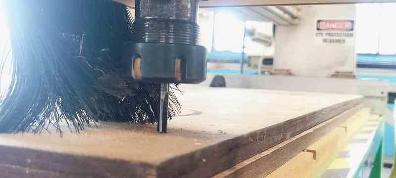
Machine Cutting and Setup Process
Before starting the machine, we prioritized safety precautions. In addition to ensuring safety, we also verified the electrical connection to confirm whether it was single-phase and securely clamped the plywood. These steps were crucial before powering on the machine.
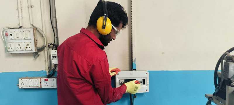
1. First, we turned on the power switch and equipped ourselves with the necessary safety gear.
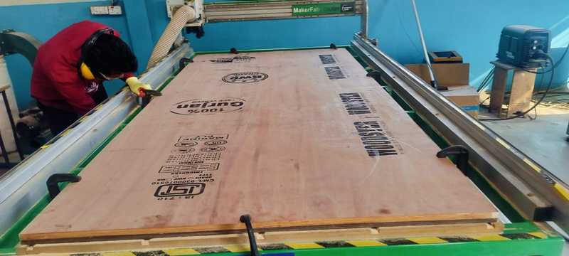
2. I cleaned the wood router and carefully clamped the plywood in place to ensure it was securely fixed.
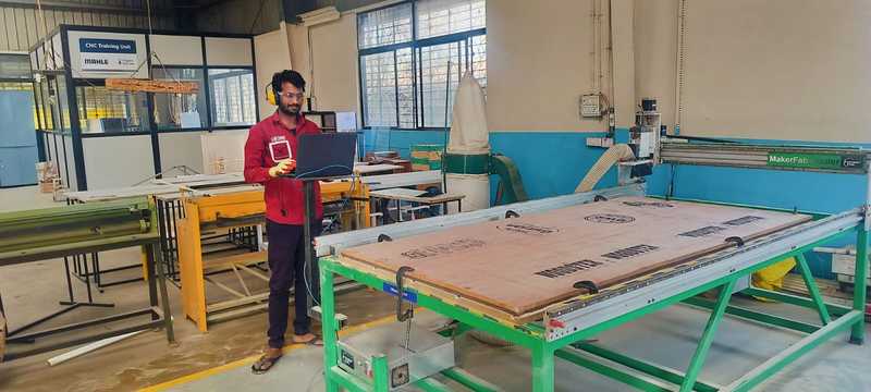
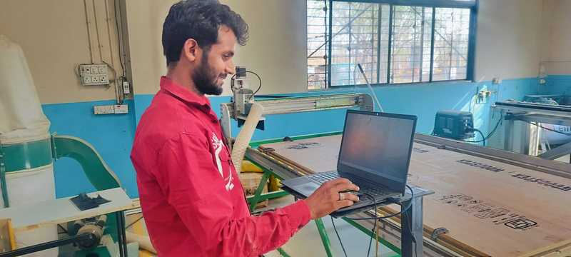
3. The wood router and glower were powered on, and I proceeded to configure the laptop to begin the setup.
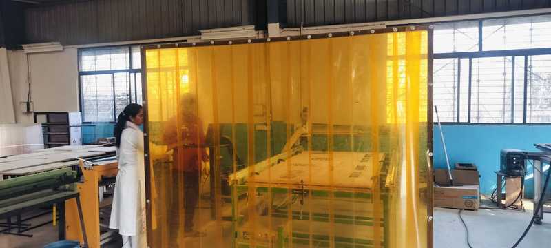
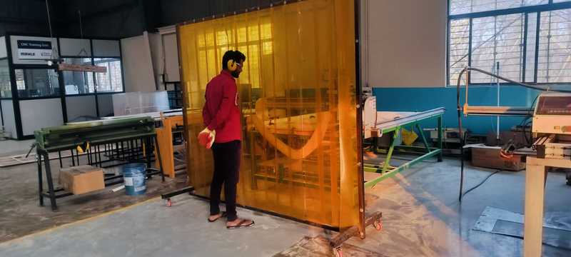
4. Before sending the design to the wood router, I set up a protective barrier around the machine for safety purposes.
5. I accurately set the machine's origin point to ensure precision in the cutting process.
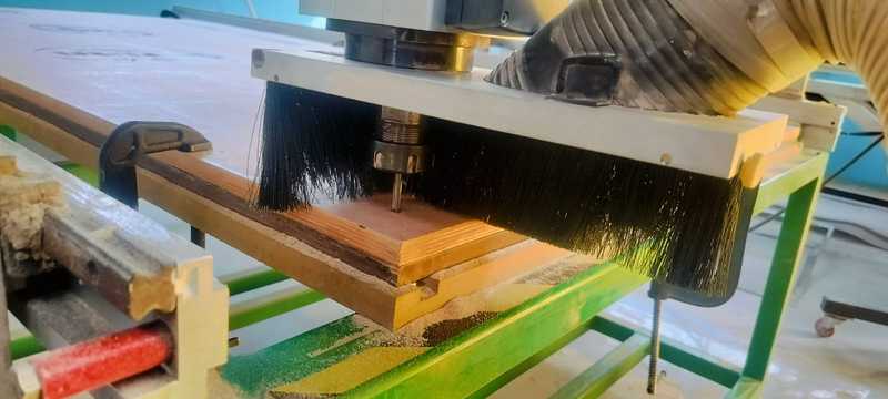
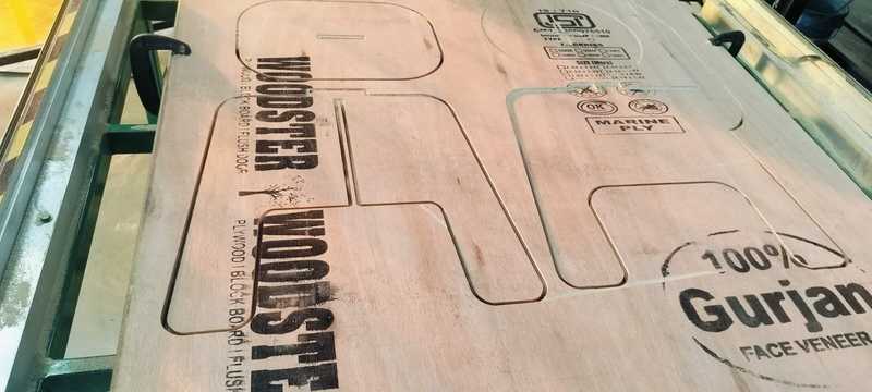
6. Initially, I sent a command to the machine to perform an inside cut, followed by an outside cut in the second step.
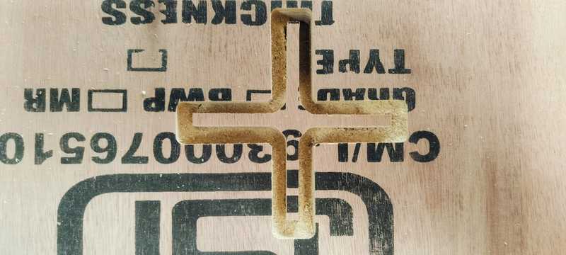
7. The inside cut was executed successfully.
8. The outside cut followed after the inside cut.
9. Safety: It is essential not to approach the machine while it is in operation.
10. The cutting process is now complete.
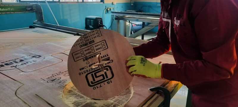
11. I carefully removed each part one by one to avoid any damage.
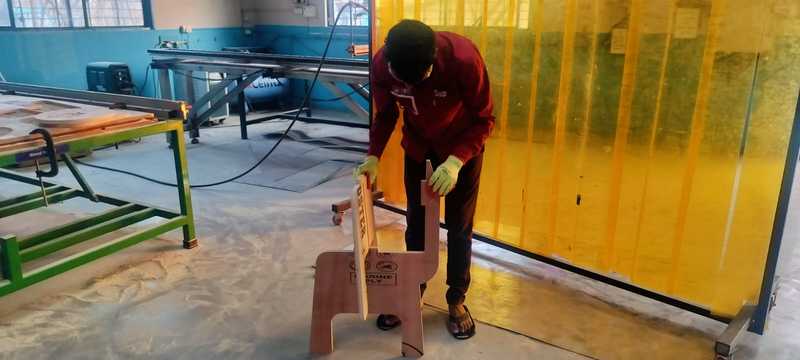
12. All the parts were successfully assembled.
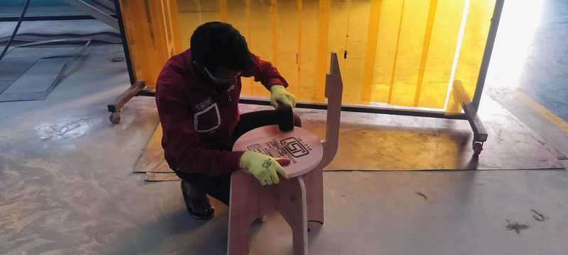
13. I encountered some difficulty during the assembly process, so I used a rubber hammer to gently press-fit the parts into place.
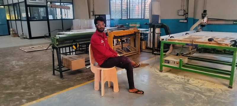
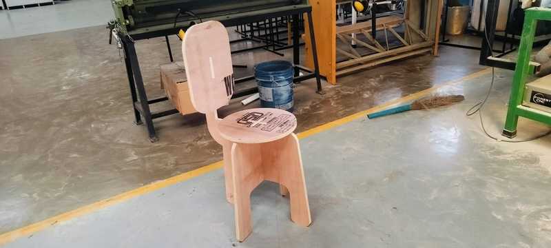
14. The final object is now ready for use.
Tools I Used
Design Tools: SolidWorks
Design Tools: Fusion 360
CNC Tool: VCarve Pro
CNC Machine: Forest CNC Router
Concept by me structured by ChatGPT.