
Assignments
Group Assignment
- Send a message between two projects.
Individual Assignment
- Design, build and connect wired or wireless node(s) with network or bus addresses and a local input and/or output devices.
GROUP ASSIGNMENT
More specific detailed from the worked done with Ernesto Castro in Fab Lab Universidad de Lima here
S E N D a m e s s a g e
My board with a button and some leds
Ernesto's board with a servomotor and a potenciometer
Both Ernesto and I had our boards designed and fabricated from week 6 and week 8. So, for this group assignment we decided to communicate each. For this part of the group assignment I will show my code and my process in the tests.
Our Instructor left us some extra group assignments:
- Communicate a button with a motor. ☑
- Communicate a potenciometer with leds ☑
p r o c e s s
1. button and motor

First we had to connect to a broker server with MQTT Broker and each wifi. For my case I connected to wifi from my cellphone to have good connection.
Broker server
Writting the code: first to connect to wifi and to connect to this broker server:
        #include <WiFi.h>
#include <PubSubClient.h>

// Wi-Fi
const char* ssid = "OfeliA phone";
const char* password = "xxxxxxxxxx";

// MQTT
const char* mqtt_server = "broker.hivemq.com";

WiFiClient espClient;
PubSubClient client(espClient);
Then stablish in the code the button pin and the setup of the action as an input when is connected:
        const int botonPin = 3;  // button pin
bool lastButtonState = HIGH;

// to avoid repeating
String lastSent = "";

void setup() {
  Serial.begin(115200);
  pinMode(botonPin, INPUT_PULLUP);

  WiFi.begin(ssid, password);
  while (WiFi.status() != WL_CONNECTED) {
    delay(500);
    Serial.print(".");
  }
  Serial.println("WiFi conectado");  // connected

  client.setServer(mqtt_server, 1883);
  while (!client.connected()) {
    Serial.print("Conectando a MQTT...");
    if (client.connect("ButtonClient")) {
      Serial.println("conectado");
    } else {
      Serial.print("falló, rc=");
      Serial.print(client.state());
      delay(5000);
    }
  }
}
To finally tell the loop id the button is ON or OFF:
void loop() {
  client.loop();

  bool buttonState = digitalRead(botonPin);

  // Detectar cambio y enviar mensaje
  if (buttonState != lastButtonState) {
    lastButtonState = buttonState;

    if (buttonState == LOW) {
      client.publish("servo/control", "ON");
      Serial.println("Botón presionado → ON");
      lastSent = "ON";
    } else {
      client.publish("servo/control", "OFF");
      Serial.println("Botón liberado → OFF");
      lastSent = "OFF";
    }
  }

  delay(50);
}
Here you can see how the button in the board 1 conbtrols the movement in the board 2.
Button controling the servo motor.
2. potenciometer and led rgb
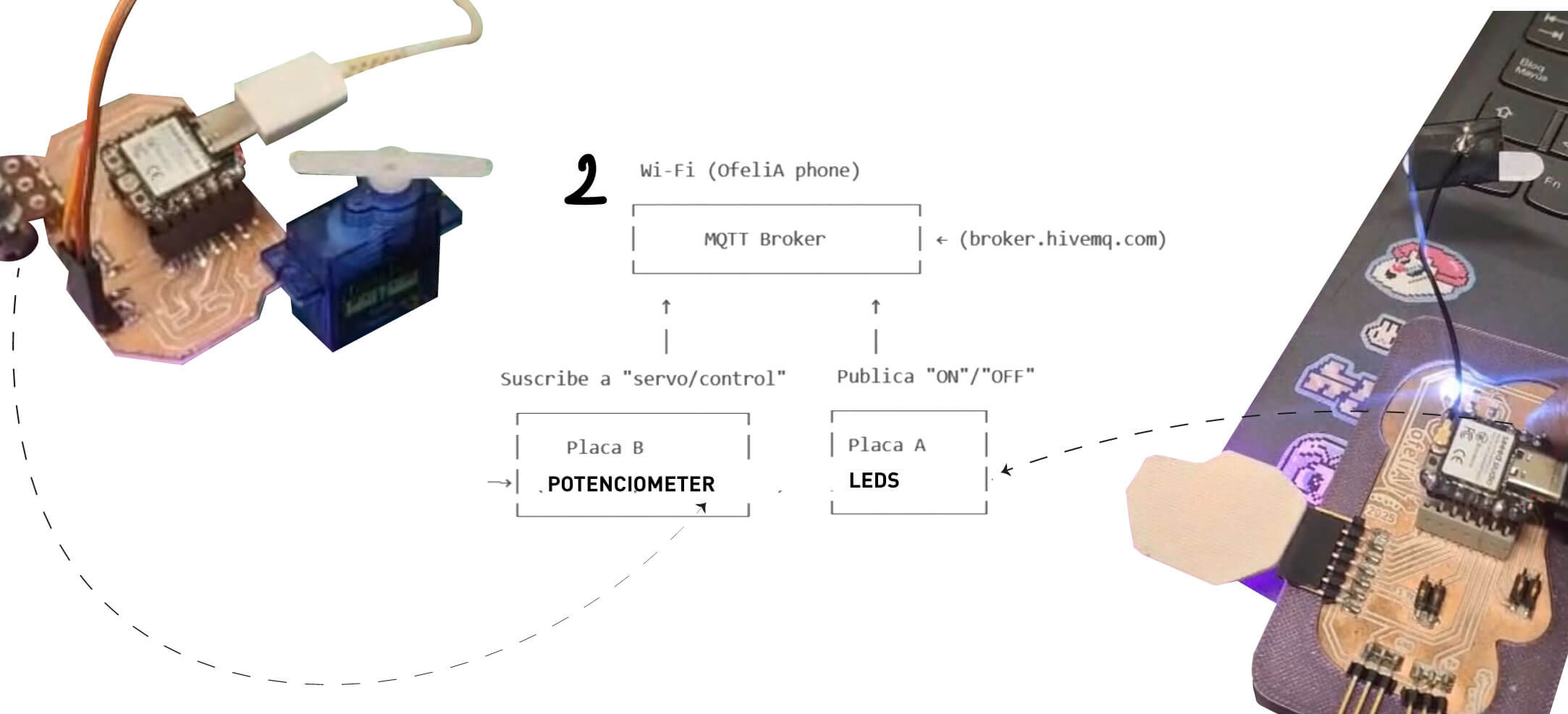
We follow the same first steps from connecting to the broker and the first code of connecting to wifi. The difference in this code was to stablish the pins of the led rgb colors as outputs each while connecting:
        int ledRojo = 10;
int ledVerde = 9;
int ledAzul = 8;

WiFiClient espClient;       // Create a WiFi client instance
PubSubClient client(espClient);  // Create a MQTT client instance

void setup() {
  pinMode(ledRojo, OUTPUT);
  pinMode(ledVerde, OUTPUT);
  pinMode(ledAzul, OUTPUT);
  Serial.begin(115200);     // Start the serial communication
  delay(10);

  // Connect to Wi-Fi
  WiFi.begin(ssid, password);   // Connect to WiFi network
  while (WiFi.status() != WL_CONNECTED) {  // Wait for WiFi connection
    delay(500);
    Serial.print(".");
  }
  Serial.println("WiFi connected");

  // Connect to MQTT Broker
  client.setServer(mqtt_server, 1883);   // Set the MQTT broker server and port
  client.setCallback(callback);   // Set callback function to handle incoming messages

  while (!client.connected()) {   // Attempt to connect to MQTT broker
    Serial.print("Attempting MQTT connection...");
    if (client.connect("ESP32C3Client")) {   // Client ID for MQTT connection
      Serial.println("connected");
      client.subscribe("arduino/uno");  // Subscribe to the topic "arduino/uno"
    } else {
      Serial.print("failed, rc=");
      Serial.print(client.state());   // Print connection status
      Serial.println(" try again in 5 seconds");
      delay(5000);   // Wait 5 seconds before retrying
    }
  }
}
And then the loop with EACH COLOR COMBINATION DEPENDING ON THE COMMUNICATION OF THE OTHER BOARD. In this case Ernesto's board was going to control letters in a keyboard to my board to read this letters and change colors by each selected letter.
MQTT Callback Example
void loop() {
  client.loop();    // Maintain MQTT connection and handle incoming messages
}

// MQTT callback function to handle incoming messages
void callback(char* topic, byte* payload, unsigned int length) {
  Serial.print("Message arrived [");
  Serial.print(topic);   // Print the topic of the incoming message
  Serial.print("] ");
  String msg;
  // Print the incoming message
 for (int i = 0; i < length; i++) {
  msg += (char)payload[i];
  }
  Serial.println(msg);
  if (msg == "A") {
  // 10 combinaciones de magenta
  analogWrite(ledRojo, 50);   // más brillante
  analogWrite(ledVerde, 255); // verde apagado
  analogWrite(ledAzul, 80);   // más brillante
  Serial.println("Magenta combo 1");
}
else if (msg == "S") {
  analogWrite(ledRojo, 70);
  analogWrite(ledVerde, 255);
  analogWrite(ledAzul, 60);
  Serial.println("Magenta combo 2");
}
else if (msg == "D") {
  analogWrite(ledRojo, 90);
  analogWrite(ledVerde, 255);
  analogWrite(ledAzul, 40);
  Serial.println("Magenta combo 3");
}
else if (msg == "F") {
  analogWrite(ledRojo, 110);
  analogWrite(ledVerde, 255);
  analogWrite(ledAzul, 30);
  Serial.println("Magenta combo 4");
}
else if (msg == "G") {
  analogWrite(ledRojo, 130);
  analogWrite(ledVerde, 255);
  analogWrite(ledAzul, 20);
  Serial.println("Magenta combo 5");
}
else if (msg == "H") {
  analogWrite(ledRojo, 150);
  analogWrite(ledVerde, 255);
  analogWrite(ledAzul, 15);
  Serial.println("Magenta combo 6");
}
else if (msg == "I") {
  analogWrite(ledRojo, 170);
  analogWrite(ledVerde, 255);
  analogWrite(ledAzul, 10);
  Serial.println("Magenta combo 7");
}
else if (msg == "J") {
  analogWrite(ledRojo, 190);
  analogWrite(ledVerde, 255);
  analogWrite(ledAzul, 5);
  Serial.println("Magenta combo 8");
}
else if (msg == "K") {
  analogWrite(ledRojo, 210);
  analogWrite(ledVerde, 255);
  analogWrite(ledAzul, 2);
  Serial.println("Magenta combo 9");
}
else if (msg == "L") {
  analogWrite(ledRojo, 230);
  analogWrite(ledVerde, 255);
  analogWrite(ledAzul, 0);
  Serial.println("Magenta combo 10");
}

  }
Here you can see the serial monitor and how both boards are communicating. One send letters and the other reads the letters to change color:
Button controling the servo motor.
And here are changing the colors by the potenciometer.
First test with a protoboard since the potenciometer board was failing.
Final test withe both boards.
INDIVIDUAL ASSIGNMENT
For the individual assignment I connected my board designed and made in week 8 to and app in my phone and to an ARDUINO UNO R3 from the fablab. First I tried to connect my board via bluetooth to an app by itself and then connected by wifi to the other board. All the tests were in order to communicate different ways of signal to control the color change in the RGB leds .
P r o c e s s
Bluetooth RGB
First I visited the seeed studio getting started page where I found a guide to understand how to use the wireless conection in the XIAO ESP32-C3 microcontroller I am using.
TO START THE BLUETOOTH CONNECTION:
Step 1. Copy and paste the code below into Arduino IDE
#include <BLEDevice.h>
#include <BLEUtils.h>
#include <BLEScan.h>
#include <BLEAdvertisedDevice.h>

int scanTime = 5; //In seconds
BLEScan* pBLEScan;

class MyAdvertisedDeviceCallbacks: public BLEAdvertisedDeviceCallbacks {
    void onResult(BLEAdvertisedDevice advertisedDevice) {
      Serial.printf("Advertised Device: %s \n", advertisedDevice.toString().c_str());
    }
};

void setup() {
  Serial.begin(115200);
  Serial.println("Scanning...");

  BLEDevice::init("");
  pBLEScan = BLEDevice::getScan(); //create new scan
  pBLEScan->setAdvertisedDeviceCallbacks(new MyAdvertisedDeviceCallbacks());
  pBLEScan->setActiveScan(true); //active scan uses more power, but get results faster
  pBLEScan->setInterval(100);
  pBLEScan->setWindow(99);  // less or equal setInterval value
}

void loop() {
  // put your main code here, to run repeatedly:
  BLEScanResults foundDevices = pBLEScan->start(scanTime, false);
  Serial.print("Devices found: ");
  Serial.println(foundDevices.getCount());
  Serial.println("Scan done!");
  pBLEScan->clearResults();   // delete results fromBLEScan buffer to release memory
  delay(2000);
}
Bluetooth conection on.
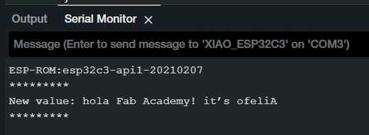
BLUETOOTH AS A SERVER:
Here we will search for XIAO ESP32C3 board using a smartphone and send out strings
to display on the serial monitor.
Step 1. Copy and paste the code below into Arduino IDE
 #include <BLEDevice.h>
#include <BLEUtils.h>
#include <BLEServer.h>

// See the following for generating UUIDs:
// https://www.uuidgenerator.net/

#define SERVICE_UUID        "4fafc201-1fb5-459e-8fcc-c5c9c331914b"
#define CHARACTERISTIC_UUID "beb5483e-36e1-4688-b7f5-ea07361b26a8"


class MyCallbacks: public BLECharacteristicCallbacks {
    void onWrite(BLECharacteristic *pCharacteristic) {
      std::string value = pCharacteristic->getValue();

      if (value.length() > 0) {
        Serial.println("*********");
        Serial.print("New value: ");
        for (int i = 0; i < value.length(); i++)
          Serial.print(value[i]);

        Serial.println();
        Serial.println("*********");
      }
    }
};

void setup() {
  Serial.begin(115200);

  BLEDevice::init("MyESP32");
  BLEServer *pServer = BLEDevice::createServer();

  BLEService *pService = pServer->createService(SERVICE_UUID);

  BLECharacteristic *pCharacteristic = pService->createCharacteristic(
                                         CHARACTERISTIC_UUID,
                                         BLECharacteristic::PROPERTY_READ |
                                         BLECharacteristic::PROPERTY_WRITE
                                       );

  pCharacteristic->setCallbacks(new MyCallbacks());

  pCharacteristic->setValue("Hello World");
  pService->start();

  BLEAdvertising *pAdvertising = pServer->getAdvertising();
  pAdvertising->start();
}

void loop() {
  // put your main code here, to run repeatedly:
  delay(2000);
}
Step 3. Download and install LightBlue App on your smartphone
Step 5. Open the LightBlue app and click Bonded tab
Step 6. Click CONNECT next to MyESP32
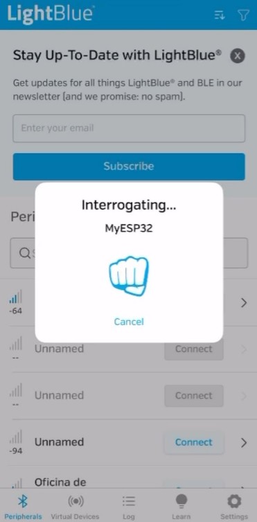
Searching bluetooth conection
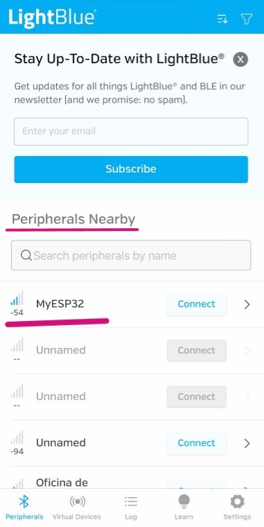
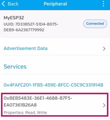
Connected to "MyESP32"
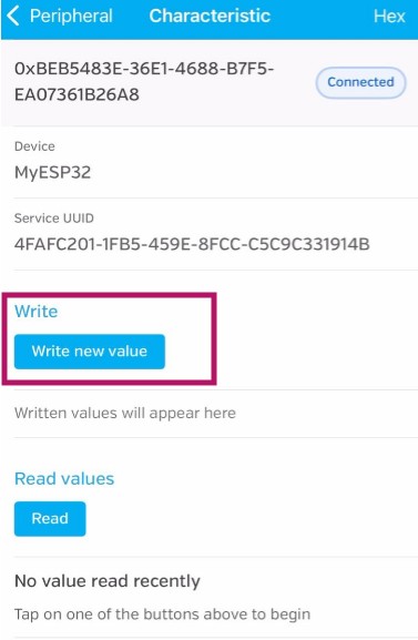
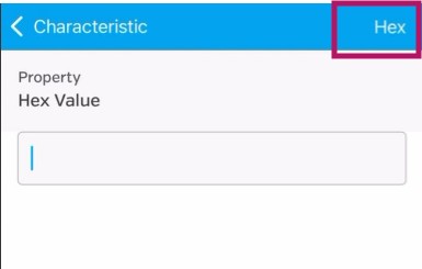
Step 7. Click the section at the very bottom which says Properties, Read, Write
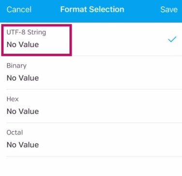
Step 8. Under Data format drop-down menu, select UTF-8 String
As I was trying to understand color control with programming, I tried to tell from my phone the color values for each RGB of the board I made in Output devices week. I adapted the code gave in this example for this with this prompt.
I have this code to turn on Bluetooth on my ESP32-C3 board. I want to connect this to an app I made in App Inventor. The app should control the RGB LEDs on my board via a slider for each color: red, green, and blue.
    #include <BLEDevice.h>
#include <BLEUtils.h>
#include <BLEServer.h>

#define SERVICE_UUID        "4fafc201-1fb5-459e-8fcc-c5c9c331914b"
#define CHARACTERISTIC_UUID "beb5483e-36e1-4688-b7f5-ea07361b26a8"

// Pines del LED RGB (ajusta según tu conexión)
#define RED_PIN   4
#define GREEN_PIN 5
#define BLUE_PIN  6

// Canales PWM para el ESP32
#define RED_CHANNEL   0
#define GREEN_CHANNEL 1
#define BLUE_CHANNEL  2

#define PWM_FREQ     5000
#define PWM_RES      8  // 8 bits: 0-255

class MyCallbacks: public BLECharacteristicCallbacks {
    void onWrite(BLECharacteristic *pCharacteristic) {
      std::string rxValue = pCharacteristic->getValue();

      if (rxValue.length() > 0) {
        Serial.print("Received: ");
        Serial.println(rxValue.c_str());

        // Espera un formato tipo "R,G,B", por ejemplo: "128,255,64"
        int r = 0, g = 0, b = 0;
        sscanf(rxValue.c_str(), "%d,%d,%d", &r, &g, &b);

        // Limita valores entre 0 y 255
        r = constrain(r, 0, 255);
        g = constrain(g, 0, 255);
        b = constrain(b, 0, 255);

        Serial.printf("Parsed -> R: %d, G: %d, B: %d\n", r, g, b);

        // Ajusta los colores usando PWM
        ledcWrite(RED_CHANNEL, r);
        ledcWrite(GREEN_CHANNEL, g);
        ledcWrite(BLUE_CHANNEL, b);
      }
    }
};

void setup() {
  Serial.begin(115200);

  // Configura PWM para cada color
  ledcSetup(RED_CHANNEL, PWM_FREQ, PWM_RES);
  ledcAttachPin(RED_PIN, RED_CHANNEL);

  ledcSetup(GREEN_CHANNEL, PWM_FREQ, PWM_RES);
  ledcAttachPin(GREEN_PIN, GREEN_CHANNEL);

  ledcSetup(BLUE_CHANNEL, PWM_FREQ, PWM_RES);
  ledcAttachPin(BLUE_PIN, BLUE_CHANNEL);

  // Inicializa en apagado
  ledcWrite(RED_CHANNEL, 0);
  ledcWrite(GREEN_CHANNEL, 0);
  ledcWrite(BLUE_CHANNEL, 0);

  // BLE
  BLEDevice::init("ESP32-RGB");
  BLEServer *pServer = BLEDevice::createServer();
  BLEService *pService = pServer->createService(SERVICE_UUID);

  BLECharacteristic *pCharacteristic = pService->createCharacteristic(
                                         CHARACTERISTIC_UUID,
                                         BLECharacteristic::PROPERTY_WRITE
                                       );
  pCharacteristic->setCallbacks(new MyCallbacks());

  pService->start();
  pServer->getAdvertising()->start();
}

void loop() {
  delay(1000); //
}
Lightblue app bluetooth control RGB leds
WiFi RGB
After making the bluetooth conection by myself my instructors wanted to connect my board with another one by wifi. For this I use the code made by Ernesto Buendia in week 14. And fot this I also use an Arduino UNO R3 board of the fablab ulima.
My board from week 8
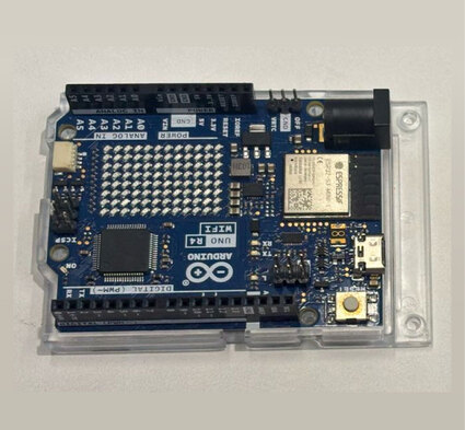
ARDUINO UNO R3 from fablab ulima
I also used the broker MQTT. This works like an intermediate between both boards but one reads the "message" and the other one public "the message". First I will just start the wifi conection in both and then send a message.
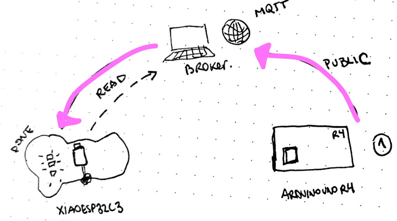
The process of the wifi communication
First, I started the conection with this code in my XIAO ESP32-C3 board:
    #include <WiFi.h>
#include <PubSubClient.h>

//  network credentials
const char* ssid = "wifi";
const char* password = "password";

//  MQTT broker IP address or hostname
const char* mqtt_server = "broker.hivemq.com";

WiFiClient espClient;       // Create a WiFi client instance
PubSubClient client(espClient);  // Create a MQTT client instance

void setup() {
  Serial.begin(115200);     // Start the serial communication
  delay(10);

  // Connect to Wi-Fi
  WiFi.begin(ssid, password);   // Connect to WiFi network
  while (WiFi.status() != WL_CONNECTED) {  // Wait for WiFi connection
    delay(500);
    Serial.print(".");
  }
  Serial.println("WiFi connected");

  // Connect to MQTT Broker
  client.setServer(mqtt_server, 1883);   // Set the MQTT broker server and port
  client.setCallback(callback);   // Set callback function to handle incoming messages

  while (!client.connected()) {   // Attempt to connect to MQTT broker
    Serial.print("Attempting MQTT connection...");
    if (client.connect("ESP32C3Client")) {   // Client ID for MQTT connection
      Serial.println("connected");
      client.subscribe("arduino/uno");  // Subscribe to the topic "arduino/uno"
    } else {
      Serial.print("failed, rc=");
      Serial.print(client.state());   // Print connection status
      Serial.println(" try again in 5 seconds");
      delay(5000);   // Wait 5 seconds before retrying
    }
  }
}
And this code in the ARDUINO UNO R3 board:
    #include <WiFi.h>
#include <PubSubClient.h>

// Replace with your network credentials
const char* ssid = "wifi";
const char* password = "password";


const char* mqtt_server = "broker.hivemq.com";

WiFiClient espClient; // Client WiFi to connect MQTT server
PubSubClient client(espClient); // Client MQTT that uses client WiFi


void setup() {

  Serial.begin(115200); // Inicializa la comunicación serial a 115200 baudios
  delay(10);

  // Connect to Wi-Fi
  WiFi.begin(ssid, password); // Start connection to wifi red
  while (WiFi.status() != WL_CONNECTED) { // Wait until the connection is successful
    delay(500);
    Serial.print("."); // Print a dot every 500 ms while connecting
  }
  Serial.println("WiFi connected"); // Print a message when the Wi-Fi connection is successful

  // Connect to MQTT Broker
  client.setServer(mqtt_server, 1883); // Set the MQTT client to connect to the server at port 1883

  while (!client.connected()) { // Try to connect to the MQTT broker until successful
    Serial.print("Attempting MQTT connection...");
    if (client.connect("ESP32S3Client")) { // Try to connect with the ID "ESP32S3Client"
      Serial.println("connected"); // Print a message when the MQTT connection is successful
    } else {
      Serial.print("failed, rc=");
      Serial.print(client.state()); // Print the MQTT client state if the connection fails
      Serial.println(" try again in 5 seconds"); // Wait 5 seconds before trying to reconnect
      delay(5000);
    }
  }
}
After both were connected I send a message first adding this in the XIAO ESP32-C3 code to read the message:
      void loop() {
  client.loop();    // Maintain MQTT connection and handle incoming messages
}

// MQTT callback function to handle incoming messages
void callback(char* topic, byte* payload, unsigned int length) {
  Serial.print("Message arrived [");
  Serial.print(topic);   // Print the topic of the incoming message
  Serial.print("] ");

  // Print the incoming message
  for (int i = 0; i < length; i++) {
    Serial.print((char)payload[i]);
  }
  Serial.println();
}
And add this in the Arduino UNO R3 code at the end where I wrote the message:
     void loop() {
  // Send a test message
  client.loop();
  client.publish("arduino/uno", "hola Fab Academy! it's ofeliA"); // Publish a message to the topic "arduino/uno"
  delay(5000);  // Wait 5 seconds before sending the next message
}
From the XIAO ESP32C3 to the ARDUINO UNO serial monitor
Then I wanted to try the communication by in the ARDUINO UNO R3 typing some letters in order to control the color change in the XIAO ESP32-C3 RGB led board:
This code in the XIAO ESP32C3 telling to read the letters as a color combination:
    #include <WiFi.h>
#include <PubSubClient.h>

// network credentials
const char* ssid = "wifi";
const char* password = "password";

// MQTT broker IP address or hostname
const char* mqtt_server = "broker.hivemq.com";

int ledRojo = 10;
int ledVerde = 9;
int ledAzul = 8;

WiFiClient espClient;       // Create a WiFi client instance
PubSubClient client(espClient);  // Create a MQTT client instance

void setup() {
  pinMode(ledRojo, OUTPUT);
  pinMode(ledVerde, OUTPUT);
  pinMode(ledAzul, OUTPUT);
  Serial.begin(115200);     // Start the serial communication
  delay(10);

  // Connect to Wi-Fi
  WiFi.begin(ssid, password);   // Connect to WiFi network
  while (WiFi.status() != WL_CONNECTED) {  // Wait for WiFi connection
    delay(500);
    Serial.print(".");
  }
  Serial.println("WiFi connected");

  // Connect to MQTT Broker
  client.setServer(mqtt_server, 1883);   // Set the MQTT broker server and port
  client.setCallback(callback);   // Set callback function to handle incoming messages

  while (!client.connected()) {   // Attempt to connect to MQTT broker
    Serial.print("Attempting MQTT connection...");
    if (client.connect("ESP32C3Client")) {   // Client ID for MQTT connection
      Serial.println("connected");
      client.subscribe("arduino/uno");  // Subscribe to the topic "arduino/uno"
    } else {
      Serial.print("failed, rc=");
      Serial.print(client.state());   // Print connection status
      Serial.println(" try again in 5 seconds");
      delay(5000);   // Wait 5 seconds before retrying
    }
  }
}

void loop() {
  client.loop();    // Maintain MQTT connection and handle incoming messages
}

// MQTT callback function to handle incoming messages
void callback(char* topic, byte* payload, unsigned int length) {
  Serial.print("Message arrived [");
  Serial.print(topic);   // Print the topic of the incoming message
  Serial.print("] ");
  String msg;
  // Print the incoming message
  for (int i = 0; i < length; i++) {
    msg += (char)payload[i];
  }
  Serial.println(msg);
  if (msg == "A") {
  // 10 combinaciones de magenta
  analogWrite(ledRojo, 50);   // más brillante
  analogWrite(ledVerde, 255); // verde apagado
  analogWrite(ledAzul, 80);   // más brillante
  Serial.println("Magenta combo 1");
}
else if (msg == "S") {
  analogWrite(ledRojo, 70);
  analogWrite(ledVerde, 255);
  analogWrite(ledAzul, 60);
  Serial.println("Magenta combo 2");
}
else if (msg == "D") {
  analogWrite(ledRojo, 90);
  analogWrite(ledVerde, 255);
  analogWrite(ledAzul, 40);
  Serial.println("Magenta combo 3");
}
else if (msg == "F") {
  analogWrite(ledRojo, 110);
  analogWrite(ledVerde, 255);
  analogWrite(ledAzul, 30);
  Serial.println("Magenta combo 4");
}
else if (msg == "G") {
  analogWrite(ledRojo, 130);
  analogWrite(ledVerde, 255);
  analogWrite(ledAzul, 20);
  Serial.println("Magenta combo 5");
}
else if (msg == "H") {
  analogWrite(ledRojo, 150);
  analogWrite(ledVerde, 255);
  analogWrite(ledAzul, 15);
  Serial.println("Magenta combo 6");
}
else if (msg == "I") {
  analogWrite(ledRojo, 170);
  analogWrite(ledVerde, 255);
  analogWrite(ledAzul, 10);
  Serial.println("Magenta combo 7");
}
else if (msg == "J") {
  analogWrite(ledRojo, 190);
  analogWrite(ledVerde, 255);
  analogWrite(ledAzul, 5);
  Serial.println("Magenta combo 8");
}
else if (msg == "K") {
  analogWrite(ledRojo, 210);
  analogWrite(ledVerde, 255);
  analogWrite(ledAzul, 2);
  Serial.println("Magenta combo 9");
}
else if (msg == "L") {
  analogWrite(ledRojo, 230);
  analogWrite(ledVerde, 255);
  analogWrite(ledAzul, 0);
  Serial.println("Magenta combo 10");
}
  }
And this is the ARDUINO UNO R3 to send the letters:
#include <WiFiS3.h>
#include <PubSubClient.h>

// Replace with your network credentials
const char* ssid = "OfeliA phone"; //ssid network
const char* password = "ofelias127"; //Password to ssid network

const char* mqtt_server = "broker.hivemq.com"; // Address MQTT server

WiFiClient espClient; // Client WiFi to connect MQTT server
PubSubClient client(espClient); // Client MQTT that uses client WiFi

void setup() {
  Serial.begin(115200); // Inicializa la comunicación serial a 115200 baudios
  delay(10);

  // Connect to Wi-Fi
  WiFi.begin(ssid, password); // Start connection to wifi red
  while (WiFi.status() != WL_CONNECTED) { // Wait until the connection is successful
    delay(500);
    Serial.println("."); // Print a dot every 500 ms while connecting
  }
  Serial.println("WiFi connected"); // Print a message when the Wi-Fi connection is successful

  // Connect to MQTT Broker
  client.setServer(mqtt_server, 1883); // Set the MQTT client to connect to the server at port 1883

  while (!client.connected()) { // Try to connect to the MQTT broker until successful
    Serial.print("Attempting MQTT connection...");
    if (client.connect("ESP32S3Client")) { // Try to connect with the ID "ESP32S3Client"
      Serial.println("connected"); // Print a message when the MQTT connection is successful
    } else {
      Serial.print("failed, rc=");
      Serial.print(client.state()); // Print the MQTT client state if the connection fails
      Serial.println(" try again in 5 seconds"); // Wait 5 seconds before trying to reconnect
      delay(5000);
    }
  }
}

void loop() {
  // Send a test message
  client.loop();
  if (Serial.available()) {   // Check if data is available on serial port
    char c = Serial.read();   // Read a character from serial input
    Serial.print(c);
    if (c == 'A' || c == 'S' || c == 'D' || c == 'F' ||
        c == 'G' || c == 'H' || c == 'J' || c == 'K' ||
        c == 'L' || c == 'Y') {
      client.publish("arduino/uno", String(c).c_str()); // Envia la tecla por MQTT
      Serial.print("Sent: ");
      Serial.println(c);
    }
  }
}
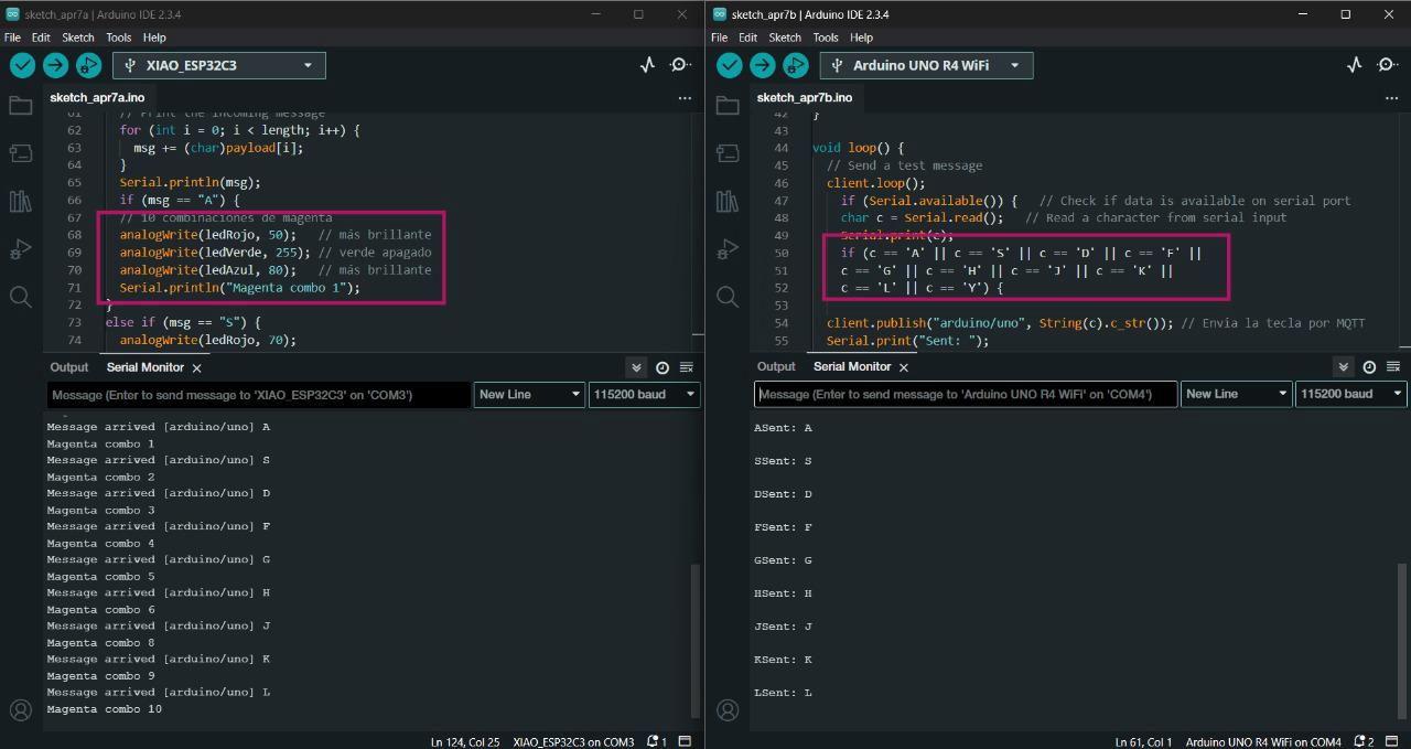
Message send from the ARDUINO board in the right and message read in the XIAO board in the left.
Test changing colors from shades of blue to magenta.
What's next?
Maybe thinking about making an app to control the color change in my final project connected by bluetooth.
Our Instructor left us some extra group assignments:
- Communicate a button with a motor. ☑
- Communicate a potenciometer with leds ☑
1. button and motor
First we had to connect to a broker server with MQTT Broker and each wifi. For my case I connected to wifi from my cellphone to have good connection.
Broker server
Writting the code: first to connect to wifi and to connect to this broker server:
#include <WiFi.h> #include <PubSubClient.h> // Wi-Fi const char* ssid = "OfeliA phone"; const char* password = "xxxxxxxxxx"; // MQTT const char* mqtt_server = "broker.hivemq.com"; WiFiClient espClient; PubSubClient client(espClient);
Then stablish in the code the button pin and the setup of the action as an input when is connected:
const int botonPin = 3; // button pin bool lastButtonState = HIGH; // to avoid repeating String lastSent = ""; void setup() { Serial.begin(115200); pinMode(botonPin, INPUT_PULLUP); WiFi.begin(ssid, password); while (WiFi.status() != WL_CONNECTED) { delay(500); Serial.print("."); } Serial.println("WiFi conectado"); // connected client.setServer(mqtt_server, 1883); while (!client.connected()) { Serial.print("Conectando a MQTT..."); if (client.connect("ButtonClient")) { Serial.println("conectado"); } else { Serial.print("falló, rc="); Serial.print(client.state()); delay(5000); } } }
To finally tell the loop id the button is ON or OFF:
void loop() {
client.loop();
bool buttonState = digitalRead(botonPin);
// Detectar cambio y enviar mensaje
if (buttonState != lastButtonState) {
lastButtonState = buttonState;
if (buttonState == LOW) {
client.publish("servo/control", "ON");
Serial.println("Botón presionado → ON");
lastSent = "ON";
} else {
client.publish("servo/control", "OFF");
Serial.println("Botón liberado → OFF");
lastSent = "OFF";
}
}
delay(50);
}
Here you can see how the button in the board 1 conbtrols the movement in the board 2.
Button controling the servo motor.
2. potenciometer and led rgb
We follow the same first steps from connecting to the broker and the first code of connecting to wifi. The difference in this code was to stablish the pins of the led rgb colors as outputs each while connecting:
int ledRojo = 10; int ledVerde = 9; int ledAzul = 8; WiFiClient espClient; // Create a WiFi client instance PubSubClient client(espClient); // Create a MQTT client instance void setup() { pinMode(ledRojo, OUTPUT); pinMode(ledVerde, OUTPUT); pinMode(ledAzul, OUTPUT); Serial.begin(115200); // Start the serial communication delay(10); // Connect to Wi-Fi WiFi.begin(ssid, password); // Connect to WiFi network while (WiFi.status() != WL_CONNECTED) { // Wait for WiFi connection delay(500); Serial.print("."); } Serial.println("WiFi connected"); // Connect to MQTT Broker client.setServer(mqtt_server, 1883); // Set the MQTT broker server and port client.setCallback(callback); // Set callback function to handle incoming messages while (!client.connected()) { // Attempt to connect to MQTT broker Serial.print("Attempting MQTT connection..."); if (client.connect("ESP32C3Client")) { // Client ID for MQTT connection Serial.println("connected"); client.subscribe("arduino/uno"); // Subscribe to the topic "arduino/uno" } else { Serial.print("failed, rc="); Serial.print(client.state()); // Print connection status Serial.println(" try again in 5 seconds"); delay(5000); // Wait 5 seconds before retrying } } }
And then the loop with EACH COLOR COMBINATION DEPENDING ON THE COMMUNICATION OF THE OTHER BOARD. In this case Ernesto's board was going to control letters in a keyboard to my board to read this letters and change colors by each selected letter.
MQTT Callback Example
void loop() {
client.loop(); // Maintain MQTT connection and handle incoming messages
}
// MQTT callback function to handle incoming messages
void callback(char* topic, byte* payload, unsigned int length) {
Serial.print("Message arrived [");
Serial.print(topic); // Print the topic of the incoming message
Serial.print("] ");
String msg;
// Print the incoming message
for (int i = 0; i < length; i++) {
msg += (char)payload[i];
}
Serial.println(msg);
if (msg == "A") {
// 10 combinaciones de magenta
analogWrite(ledRojo, 50); // más brillante
analogWrite(ledVerde, 255); // verde apagado
analogWrite(ledAzul, 80); // más brillante
Serial.println("Magenta combo 1");
}
else if (msg == "S") {
analogWrite(ledRojo, 70);
analogWrite(ledVerde, 255);
analogWrite(ledAzul, 60);
Serial.println("Magenta combo 2");
}
else if (msg == "D") {
analogWrite(ledRojo, 90);
analogWrite(ledVerde, 255);
analogWrite(ledAzul, 40);
Serial.println("Magenta combo 3");
}
else if (msg == "F") {
analogWrite(ledRojo, 110);
analogWrite(ledVerde, 255);
analogWrite(ledAzul, 30);
Serial.println("Magenta combo 4");
}
else if (msg == "G") {
analogWrite(ledRojo, 130);
analogWrite(ledVerde, 255);
analogWrite(ledAzul, 20);
Serial.println("Magenta combo 5");
}
else if (msg == "H") {
analogWrite(ledRojo, 150);
analogWrite(ledVerde, 255);
analogWrite(ledAzul, 15);
Serial.println("Magenta combo 6");
}
else if (msg == "I") {
analogWrite(ledRojo, 170);
analogWrite(ledVerde, 255);
analogWrite(ledAzul, 10);
Serial.println("Magenta combo 7");
}
else if (msg == "J") {
analogWrite(ledRojo, 190);
analogWrite(ledVerde, 255);
analogWrite(ledAzul, 5);
Serial.println("Magenta combo 8");
}
else if (msg == "K") {
analogWrite(ledRojo, 210);
analogWrite(ledVerde, 255);
analogWrite(ledAzul, 2);
Serial.println("Magenta combo 9");
}
else if (msg == "L") {
analogWrite(ledRojo, 230);
analogWrite(ledVerde, 255);
analogWrite(ledAzul, 0);
Serial.println("Magenta combo 10");
}
}
Here you can see the serial monitor and how both boards are communicating. One send letters and the other reads the letters to change color:
Button controling the servo motor.
And here are changing the colors by the potenciometer.
First test with a protoboard since the potenciometer board was failing.
Final test withe both boards.
INDIVIDUAL ASSIGNMENT
For the individual assignment I connected my board designed and made in week 8 to and app in my phone and to an ARDUINO UNO R3 from the fablab. First I tried to connect my board via bluetooth to an app by itself and then connected by wifi to the other board. All the tests were in order to communicate different ways of signal to control the color change in the RGB leds .
P r o c e s s
Bluetooth RGB
First I visited the seeed studio getting started page where I found a guide to understand how to use the wireless conection in the XIAO ESP32-C3 microcontroller I am using.
TO START THE BLUETOOTH CONNECTION:
Step 1. Copy and paste the code below into Arduino IDE#include <BLEDevice.h> #include <BLEUtils.h> #include <BLEScan.h> #include <BLEAdvertisedDevice.h> int scanTime = 5; //In seconds BLEScan* pBLEScan; class MyAdvertisedDeviceCallbacks: public BLEAdvertisedDeviceCallbacks { void onResult(BLEAdvertisedDevice advertisedDevice) { Serial.printf("Advertised Device: %s \n", advertisedDevice.toString().c_str()); } }; void setup() { Serial.begin(115200); Serial.println("Scanning..."); BLEDevice::init(""); pBLEScan = BLEDevice::getScan(); //create new scan pBLEScan->setAdvertisedDeviceCallbacks(new MyAdvertisedDeviceCallbacks()); pBLEScan->setActiveScan(true); //active scan uses more power, but get results faster pBLEScan->setInterval(100); pBLEScan->setWindow(99); // less or equal setInterval value } void loop() { // put your main code here, to run repeatedly: BLEScanResults foundDevices = pBLEScan->start(scanTime, false); Serial.print("Devices found: "); Serial.println(foundDevices.getCount()); Serial.println("Scan done!"); pBLEScan->clearResults(); // delete results fromBLEScan buffer to release memory delay(2000); }
Bluetooth conection on.
BLUETOOTH AS A SERVER:
Here we will search for XIAO ESP32C3 board using a smartphone and send out strings to display on the serial monitor.
Step 1. Copy and paste the code below into Arduino IDE#include <BLEDevice.h> #include <BLEUtils.h> #include <BLEServer.h> // See the following for generating UUIDs: // https://www.uuidgenerator.net/ #define SERVICE_UUID "4fafc201-1fb5-459e-8fcc-c5c9c331914b" #define CHARACTERISTIC_UUID "beb5483e-36e1-4688-b7f5-ea07361b26a8" class MyCallbacks: public BLECharacteristicCallbacks { void onWrite(BLECharacteristic *pCharacteristic) { std::string value = pCharacteristic->getValue(); if (value.length() > 0) { Serial.println("*********"); Serial.print("New value: "); for (int i = 0; i < value.length(); i++) Serial.print(value[i]); Serial.println(); Serial.println("*********"); } } }; void setup() { Serial.begin(115200); BLEDevice::init("MyESP32"); BLEServer *pServer = BLEDevice::createServer(); BLEService *pService = pServer->createService(SERVICE_UUID); BLECharacteristic *pCharacteristic = pService->createCharacteristic( CHARACTERISTIC_UUID, BLECharacteristic::PROPERTY_READ | BLECharacteristic::PROPERTY_WRITE ); pCharacteristic->setCallbacks(new MyCallbacks()); pCharacteristic->setValue("Hello World"); pService->start(); BLEAdvertising *pAdvertising = pServer->getAdvertising(); pAdvertising->start(); } void loop() { // put your main code here, to run repeatedly: delay(2000); }Step 3. Download and install LightBlue App on your smartphone
Step 5. Open the LightBlue app and click Bonded tab
Step 6. Click CONNECT next to MyESP32
Searching bluetooth conection
Connected to "MyESP32"
Step 7. Click the section at the very bottom which says Properties, Read, Write
Step 8. Under Data format drop-down menu, select UTF-8 String
As I was trying to understand color control with programming, I tried to tell from my phone the color values for each RGB of the board I made in Output devices week. I adapted the code gave in this example for this with this prompt.
I have this code to turn on Bluetooth on my ESP32-C3 board. I want to connect this to an app I made in App Inventor. The app should control the RGB LEDs on my board via a slider for each color: red, green, and blue.
#include <BLEDevice.h> #include <BLEUtils.h> #include <BLEServer.h> #define SERVICE_UUID "4fafc201-1fb5-459e-8fcc-c5c9c331914b" #define CHARACTERISTIC_UUID "beb5483e-36e1-4688-b7f5-ea07361b26a8" // Pines del LED RGB (ajusta según tu conexión) #define RED_PIN 4 #define GREEN_PIN 5 #define BLUE_PIN 6 // Canales PWM para el ESP32 #define RED_CHANNEL 0 #define GREEN_CHANNEL 1 #define BLUE_CHANNEL 2 #define PWM_FREQ 5000 #define PWM_RES 8 // 8 bits: 0-255 class MyCallbacks: public BLECharacteristicCallbacks { void onWrite(BLECharacteristic *pCharacteristic) { std::string rxValue = pCharacteristic->getValue(); if (rxValue.length() > 0) { Serial.print("Received: "); Serial.println(rxValue.c_str()); // Espera un formato tipo "R,G,B", por ejemplo: "128,255,64" int r = 0, g = 0, b = 0; sscanf(rxValue.c_str(), "%d,%d,%d", &r, &g, &b); // Limita valores entre 0 y 255 r = constrain(r, 0, 255); g = constrain(g, 0, 255); b = constrain(b, 0, 255); Serial.printf("Parsed -> R: %d, G: %d, B: %d\n", r, g, b); // Ajusta los colores usando PWM ledcWrite(RED_CHANNEL, r); ledcWrite(GREEN_CHANNEL, g); ledcWrite(BLUE_CHANNEL, b); } } }; void setup() { Serial.begin(115200); // Configura PWM para cada color ledcSetup(RED_CHANNEL, PWM_FREQ, PWM_RES); ledcAttachPin(RED_PIN, RED_CHANNEL); ledcSetup(GREEN_CHANNEL, PWM_FREQ, PWM_RES); ledcAttachPin(GREEN_PIN, GREEN_CHANNEL); ledcSetup(BLUE_CHANNEL, PWM_FREQ, PWM_RES); ledcAttachPin(BLUE_PIN, BLUE_CHANNEL); // Inicializa en apagado ledcWrite(RED_CHANNEL, 0); ledcWrite(GREEN_CHANNEL, 0); ledcWrite(BLUE_CHANNEL, 0); // BLE BLEDevice::init("ESP32-RGB"); BLEServer *pServer = BLEDevice::createServer(); BLEService *pService = pServer->createService(SERVICE_UUID); BLECharacteristic *pCharacteristic = pService->createCharacteristic( CHARACTERISTIC_UUID, BLECharacteristic::PROPERTY_WRITE ); pCharacteristic->setCallbacks(new MyCallbacks()); pService->start(); pServer->getAdvertising()->start(); } void loop() { delay(1000); // }
Lightblue app bluetooth control RGB leds
WiFi RGB
After making the bluetooth conection by myself my instructors wanted to connect my board with another one by wifi. For this I use the code made by Ernesto Buendia in week 14. And fot this I also use an Arduino UNO R3 board of the fablab ulima.
My board from week 8
ARDUINO UNO R3 from fablab ulima
I also used the broker MQTT. This works like an intermediate between both boards but one reads the "message" and the other one public "the message". First I will just start the wifi conection in both and then send a message.
The process of the wifi communication
First, I started the conection with this code in my XIAO ESP32-C3 board:
#include <WiFi.h> #include <PubSubClient.h> // network credentials const char* ssid = "wifi"; const char* password = "password"; // MQTT broker IP address or hostname const char* mqtt_server = "broker.hivemq.com"; WiFiClient espClient; // Create a WiFi client instance PubSubClient client(espClient); // Create a MQTT client instance void setup() { Serial.begin(115200); // Start the serial communication delay(10); // Connect to Wi-Fi WiFi.begin(ssid, password); // Connect to WiFi network while (WiFi.status() != WL_CONNECTED) { // Wait for WiFi connection delay(500); Serial.print("."); } Serial.println("WiFi connected"); // Connect to MQTT Broker client.setServer(mqtt_server, 1883); // Set the MQTT broker server and port client.setCallback(callback); // Set callback function to handle incoming messages while (!client.connected()) { // Attempt to connect to MQTT broker Serial.print("Attempting MQTT connection..."); if (client.connect("ESP32C3Client")) { // Client ID for MQTT connection Serial.println("connected"); client.subscribe("arduino/uno"); // Subscribe to the topic "arduino/uno" } else { Serial.print("failed, rc="); Serial.print(client.state()); // Print connection status Serial.println(" try again in 5 seconds"); delay(5000); // Wait 5 seconds before retrying } } }
And this code in the ARDUINO UNO R3 board:
#include <WiFi.h> #include <PubSubClient.h> // Replace with your network credentials const char* ssid = "wifi"; const char* password = "password"; const char* mqtt_server = "broker.hivemq.com"; WiFiClient espClient; // Client WiFi to connect MQTT server PubSubClient client(espClient); // Client MQTT that uses client WiFi void setup() { Serial.begin(115200); // Inicializa la comunicación serial a 115200 baudios delay(10); // Connect to Wi-Fi WiFi.begin(ssid, password); // Start connection to wifi red while (WiFi.status() != WL_CONNECTED) { // Wait until the connection is successful delay(500); Serial.print("."); // Print a dot every 500 ms while connecting } Serial.println("WiFi connected"); // Print a message when the Wi-Fi connection is successful // Connect to MQTT Broker client.setServer(mqtt_server, 1883); // Set the MQTT client to connect to the server at port 1883 while (!client.connected()) { // Try to connect to the MQTT broker until successful Serial.print("Attempting MQTT connection..."); if (client.connect("ESP32S3Client")) { // Try to connect with the ID "ESP32S3Client" Serial.println("connected"); // Print a message when the MQTT connection is successful } else { Serial.print("failed, rc="); Serial.print(client.state()); // Print the MQTT client state if the connection fails Serial.println(" try again in 5 seconds"); // Wait 5 seconds before trying to reconnect delay(5000); } } }
After both were connected I send a message first adding this in the XIAO ESP32-C3 code to read the message:
void loop() { client.loop(); // Maintain MQTT connection and handle incoming messages } // MQTT callback function to handle incoming messages void callback(char* topic, byte* payload, unsigned int length) { Serial.print("Message arrived ["); Serial.print(topic); // Print the topic of the incoming message Serial.print("] "); // Print the incoming message for (int i = 0; i < length; i++) { Serial.print((char)payload[i]); } Serial.println(); }
And add this in the Arduino UNO R3 code at the end where I wrote the message:
void loop() { // Send a test message client.loop(); client.publish("arduino/uno", "hola Fab Academy! it's ofeliA"); // Publish a message to the topic "arduino/uno" delay(5000); // Wait 5 seconds before sending the next message }
From the XIAO ESP32C3 to the ARDUINO UNO serial monitor
Then I wanted to try the communication by in the ARDUINO UNO R3 typing some letters in order to control the color change in the XIAO ESP32-C3 RGB led board:
This code in the XIAO ESP32C3 telling to read the letters as a color combination:
#include <WiFi.h> #include <PubSubClient.h> // network credentials const char* ssid = "wifi"; const char* password = "password"; // MQTT broker IP address or hostname const char* mqtt_server = "broker.hivemq.com"; int ledRojo = 10; int ledVerde = 9; int ledAzul = 8; WiFiClient espClient; // Create a WiFi client instance PubSubClient client(espClient); // Create a MQTT client instance void setup() { pinMode(ledRojo, OUTPUT); pinMode(ledVerde, OUTPUT); pinMode(ledAzul, OUTPUT); Serial.begin(115200); // Start the serial communication delay(10); // Connect to Wi-Fi WiFi.begin(ssid, password); // Connect to WiFi network while (WiFi.status() != WL_CONNECTED) { // Wait for WiFi connection delay(500); Serial.print("."); } Serial.println("WiFi connected"); // Connect to MQTT Broker client.setServer(mqtt_server, 1883); // Set the MQTT broker server and port client.setCallback(callback); // Set callback function to handle incoming messages while (!client.connected()) { // Attempt to connect to MQTT broker Serial.print("Attempting MQTT connection..."); if (client.connect("ESP32C3Client")) { // Client ID for MQTT connection Serial.println("connected"); client.subscribe("arduino/uno"); // Subscribe to the topic "arduino/uno" } else { Serial.print("failed, rc="); Serial.print(client.state()); // Print connection status Serial.println(" try again in 5 seconds"); delay(5000); // Wait 5 seconds before retrying } } } void loop() { client.loop(); // Maintain MQTT connection and handle incoming messages } // MQTT callback function to handle incoming messages void callback(char* topic, byte* payload, unsigned int length) { Serial.print("Message arrived ["); Serial.print(topic); // Print the topic of the incoming message Serial.print("] "); String msg; // Print the incoming message for (int i = 0; i < length; i++) { msg += (char)payload[i]; } Serial.println(msg); if (msg == "A") { // 10 combinaciones de magenta analogWrite(ledRojo, 50); // más brillante analogWrite(ledVerde, 255); // verde apagado analogWrite(ledAzul, 80); // más brillante Serial.println("Magenta combo 1"); } else if (msg == "S") { analogWrite(ledRojo, 70); analogWrite(ledVerde, 255); analogWrite(ledAzul, 60); Serial.println("Magenta combo 2"); } else if (msg == "D") { analogWrite(ledRojo, 90); analogWrite(ledVerde, 255); analogWrite(ledAzul, 40); Serial.println("Magenta combo 3"); } else if (msg == "F") { analogWrite(ledRojo, 110); analogWrite(ledVerde, 255); analogWrite(ledAzul, 30); Serial.println("Magenta combo 4"); } else if (msg == "G") { analogWrite(ledRojo, 130); analogWrite(ledVerde, 255); analogWrite(ledAzul, 20); Serial.println("Magenta combo 5"); } else if (msg == "H") { analogWrite(ledRojo, 150); analogWrite(ledVerde, 255); analogWrite(ledAzul, 15); Serial.println("Magenta combo 6"); } else if (msg == "I") { analogWrite(ledRojo, 170); analogWrite(ledVerde, 255); analogWrite(ledAzul, 10); Serial.println("Magenta combo 7"); } else if (msg == "J") { analogWrite(ledRojo, 190); analogWrite(ledVerde, 255); analogWrite(ledAzul, 5); Serial.println("Magenta combo 8"); } else if (msg == "K") { analogWrite(ledRojo, 210); analogWrite(ledVerde, 255); analogWrite(ledAzul, 2); Serial.println("Magenta combo 9"); } else if (msg == "L") { analogWrite(ledRojo, 230); analogWrite(ledVerde, 255); analogWrite(ledAzul, 0); Serial.println("Magenta combo 10"); } }
And this is the ARDUINO UNO R3 to send the letters:
#include <WiFiS3.h> #include <PubSubClient.h> // Replace with your network credentials const char* ssid = "OfeliA phone"; //ssid network const char* password = "ofelias127"; //Password to ssid network const char* mqtt_server = "broker.hivemq.com"; // Address MQTT server WiFiClient espClient; // Client WiFi to connect MQTT server PubSubClient client(espClient); // Client MQTT that uses client WiFi void setup() { Serial.begin(115200); // Inicializa la comunicación serial a 115200 baudios delay(10); // Connect to Wi-Fi WiFi.begin(ssid, password); // Start connection to wifi red while (WiFi.status() != WL_CONNECTED) { // Wait until the connection is successful delay(500); Serial.println("."); // Print a dot every 500 ms while connecting } Serial.println("WiFi connected"); // Print a message when the Wi-Fi connection is successful // Connect to MQTT Broker client.setServer(mqtt_server, 1883); // Set the MQTT client to connect to the server at port 1883 while (!client.connected()) { // Try to connect to the MQTT broker until successful Serial.print("Attempting MQTT connection..."); if (client.connect("ESP32S3Client")) { // Try to connect with the ID "ESP32S3Client" Serial.println("connected"); // Print a message when the MQTT connection is successful } else { Serial.print("failed, rc="); Serial.print(client.state()); // Print the MQTT client state if the connection fails Serial.println(" try again in 5 seconds"); // Wait 5 seconds before trying to reconnect delay(5000); } } } void loop() { // Send a test message client.loop(); if (Serial.available()) { // Check if data is available on serial port char c = Serial.read(); // Read a character from serial input Serial.print(c); if (c == 'A' || c == 'S' || c == 'D' || c == 'F' || c == 'G' || c == 'H' || c == 'J' || c == 'K' || c == 'L' || c == 'Y') { client.publish("arduino/uno", String(c).c_str()); // Envia la tecla por MQTT Serial.print("Sent: "); Serial.println(c); } } }