"If birds can glide for long periods of time, then why can't I?" - Orville Wright
How I got the idea of doing an animatronic wing flapping for my final project
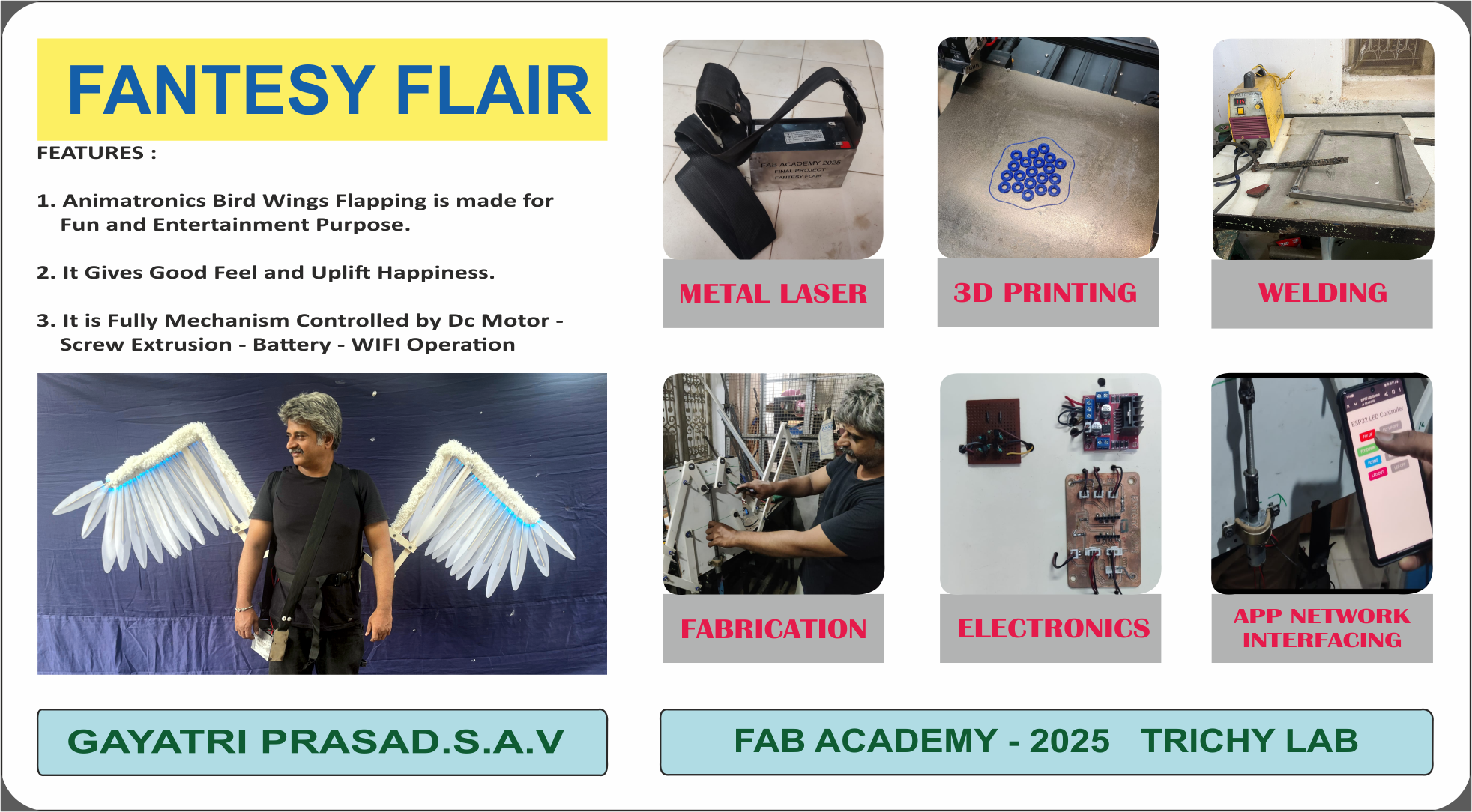
One evening, while strolling through a local park, I noticed a group of people laughing and taking turns posing in front of a beautiful, colorful wall painting of wings. Their joy was infectious—kids beamed with wide smiles, friends cheered each other on, and strangers became photographers for one another. In that moment, I realized how a simple piece of art could bring so much happiness, connection, and excitement. It felt magical—like the artwork had come to life through the people interacting with it. That experience sparked an idea in me: what if the wings weren’t just painted, but moved? What if they could flap, creating a living, breathing fantasy moment? That’s when the concept of Fantasy Flair was born—a dynamic flapping animatronic wing installation designed to turn ordinary spaces into unforgettable photo experiences, filled with wonder, emotion, and shared joy.

This experience showed me the strong visual and emotional appeal of appearing to have wings. Rather than settling for a static background, I wanted to create something dynamic and wearable—something that would truly come to life. That led me to the idea of building a wing-flapping animatronic mechanism mounted on the back of the shoulders, giving the illusion of real, moving wings attached to a person. This concept adds a unique, interactive dimension to photographs and public appearances. Mechanically, it involves lightweight linkages, servo motors, and synchronized motion control. The design had to be ergonomic, safe, and visually striking. This wearable animatronic merges the worlds of cosplay, robotics, and artistic expression, ultimately becoming the centerpiece of my final project—where creativity meets engineering.
Design

Animatronic articulated cosplay wings are a fantastic project that blends mechanics, electronics, and cosplay aesthetics. Since I already have experience in mechanical fabrication, electronics, and control systems, I am able to design an advanced wing system with smooth articulation and a lightweight structure. The entire system is wirelessly controlled through a custom Wi-Fi app, adding convenience and interactivity to the performance. yet durable materials.
Wing Mechanism Type:
Upgraded Design

The upgraded design incorporates a screw actuator to achieve precise linear motion control. A screw actuator converts rotary motion from a motor into linear displacement using a lead screw or ball screw mechanism. This allows for highly accurate and repeatable movement, making it ideal for applications like CNC systems, 3D printers, or automated flapping wing mechanisms. The design offers increased load-carrying capacity, smoother motion, and reduced backlash compared to belt-driven systems. By integrating a screw actuator, the system benefits from enhanced positional control, stability, and durability, enabling more efficient performance in compact and high-precision mechanical applications.
Scissor Mechanism: Simple, reliable, and effective for controlled extension and retraction.In 3D Model
The upgraded design features a 3D animated model in SolidWorks, showcasing the motion and function of the screw actuator system in real time. This visual representation helps in understanding mechanical interactions, assembly sequence, and movement precision. The model includes all components—motor, lead screw, nut, guide rails, and frame—accurately dimensioned and constrained. Additionally, 3D fabrication files (such as .SLDPRT and .SLDASM) are provided, allowing direct export to manufacturing formats like DXF for laser cutting or STL for 3D printing. This complete digital package ensures a smooth transition from design to production, reducing errors and enhancing build efficiency.
FABRICATION
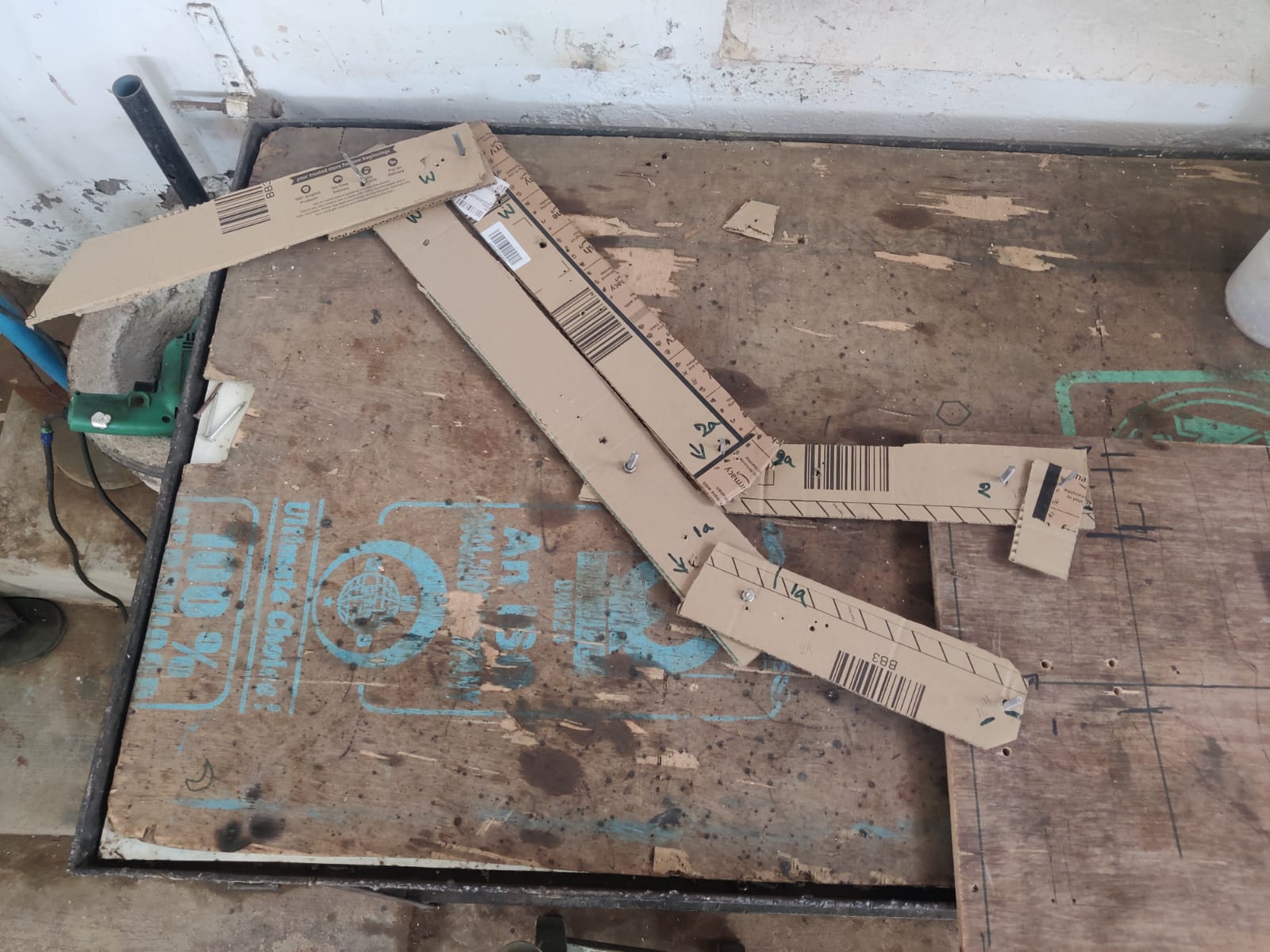
Wings test in cardboard
Validate the functionality of the flapping mechanism, a full-scale cardboard prototype of the wings was created based on the exact dimensions from the SolidWorks 3D design. The cardboard material provided a lightweight and easily modifiable option for testing the movement dynamics of the system. During the test, the wings were attached to the screw actuator assembly, and their motion was carefully observed. The setup confirmed that the wings moved freely up and down, with no friction or misalignment, simulating realistic flapping action
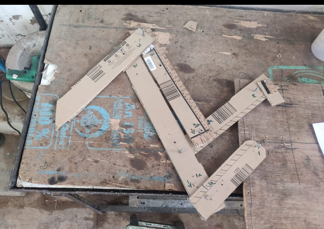
This test proved valuable for verifying joint clearances, motion range, and the accuracy of the 3D model. By conducting this low-cost preliminary test, potential design flaws could be identified and corrected before committing to final fabrication using electrical casing pipe material. The cardboard model demonstrated that the mechanical linkages and actuator path worked as intended, giving confidence in the design’s reliability and effectiveness in real-world operation.
Metal Frame for wings
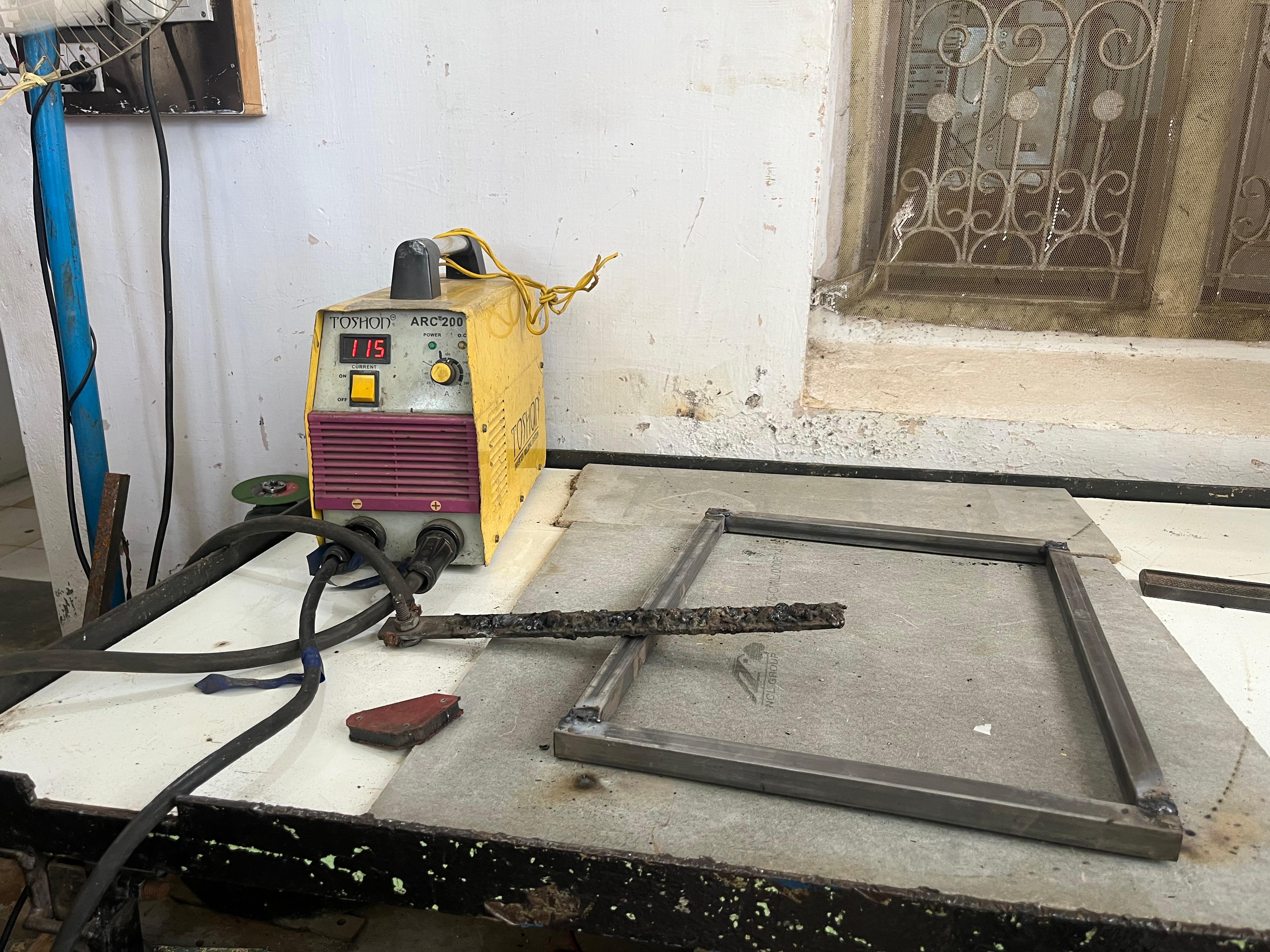
Frame750mm *300mm rectangular frame
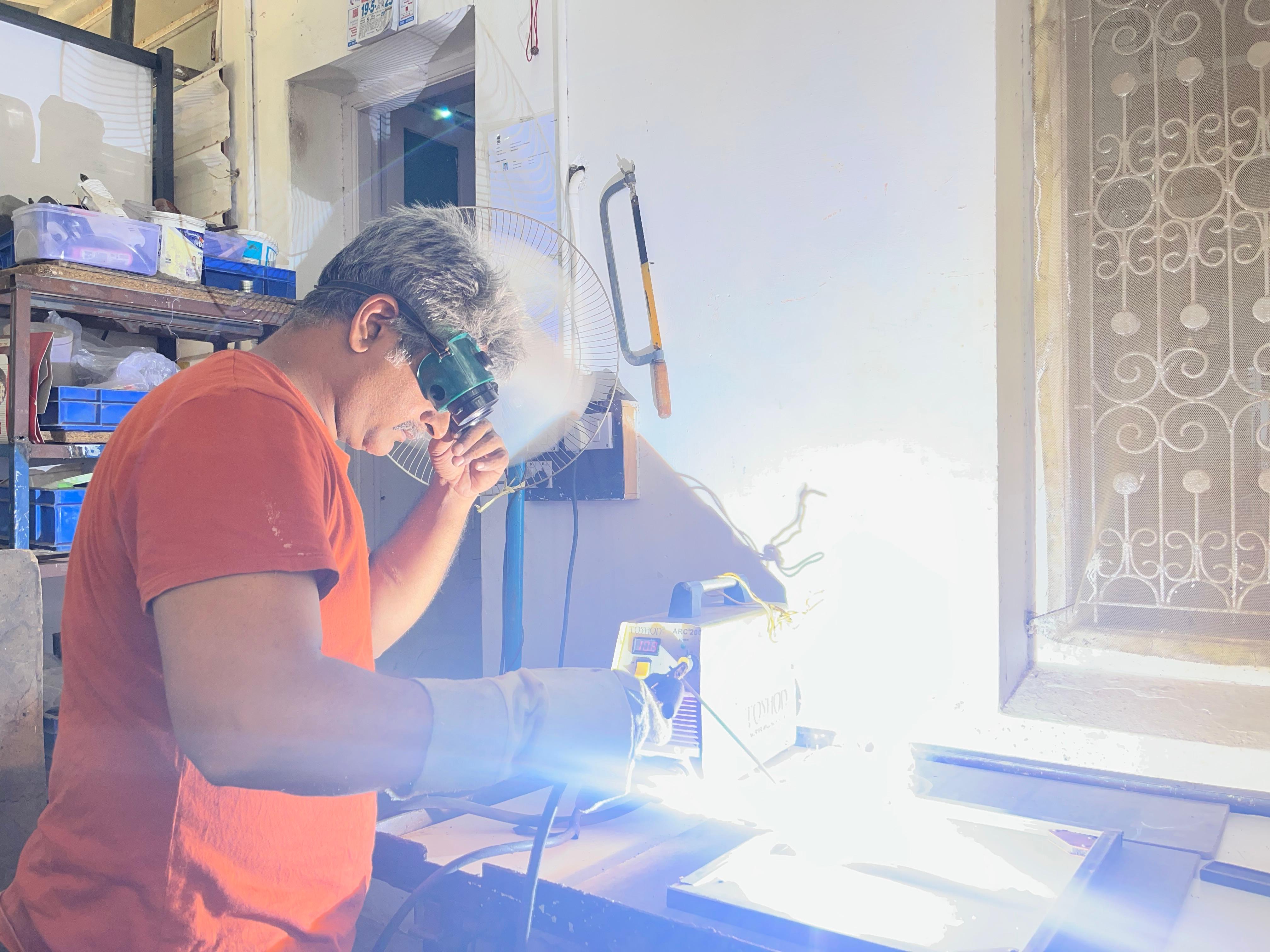
The metal frame for the wings was assembled using welding techniques to ensure structural strength and rigidity. Mild steel square pipes and flat bars were cut to precise lengths based on the 3D design and then tack-welded in place to verify alignment before full welding. Key joints—such as actuator mounts, vertical supports, and wing hinge holders—were reinforced with fillet welds to withstand the dynamic loads of continuous flapping motion.
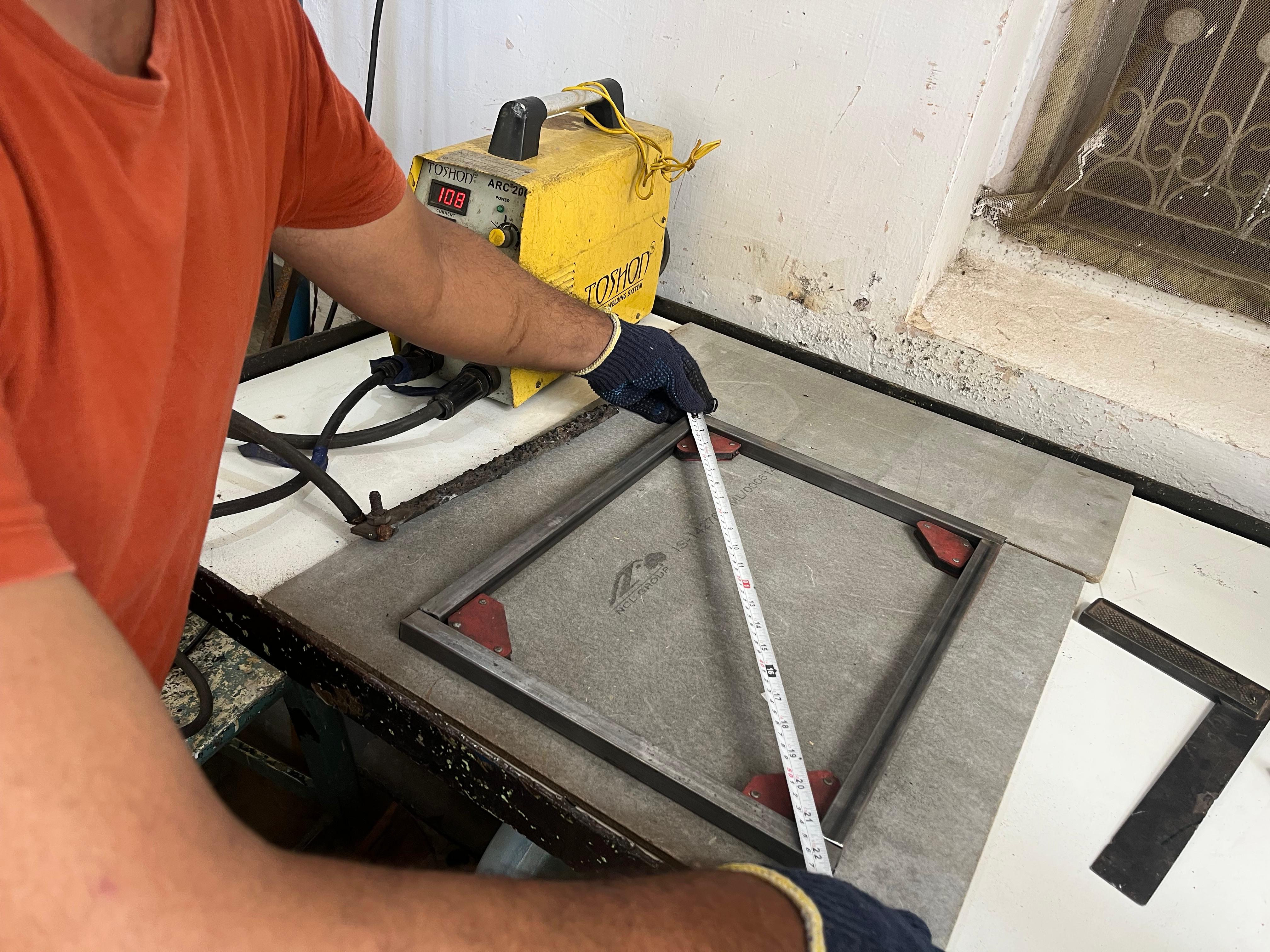
Welding provides a permanent and vibration-resistant connection, essential for mechanical stability during operation. After welding, the frame was cleaned, deburred, and painted to prevent rust and enhance durability, ensuring reliable performance for long-term use.
Materials
The materials for the electrical system were selected and fabricated based on the 3D design to support two wing motors (actuators) and LED lights as a feature. PVC electrical casing pipes were used to safely route wires from the control unit to the motors and LEDs. The pipes were cut to length and drilled at precise locations to allow wire entry and exit points, following the cable path defined in the 3D model.
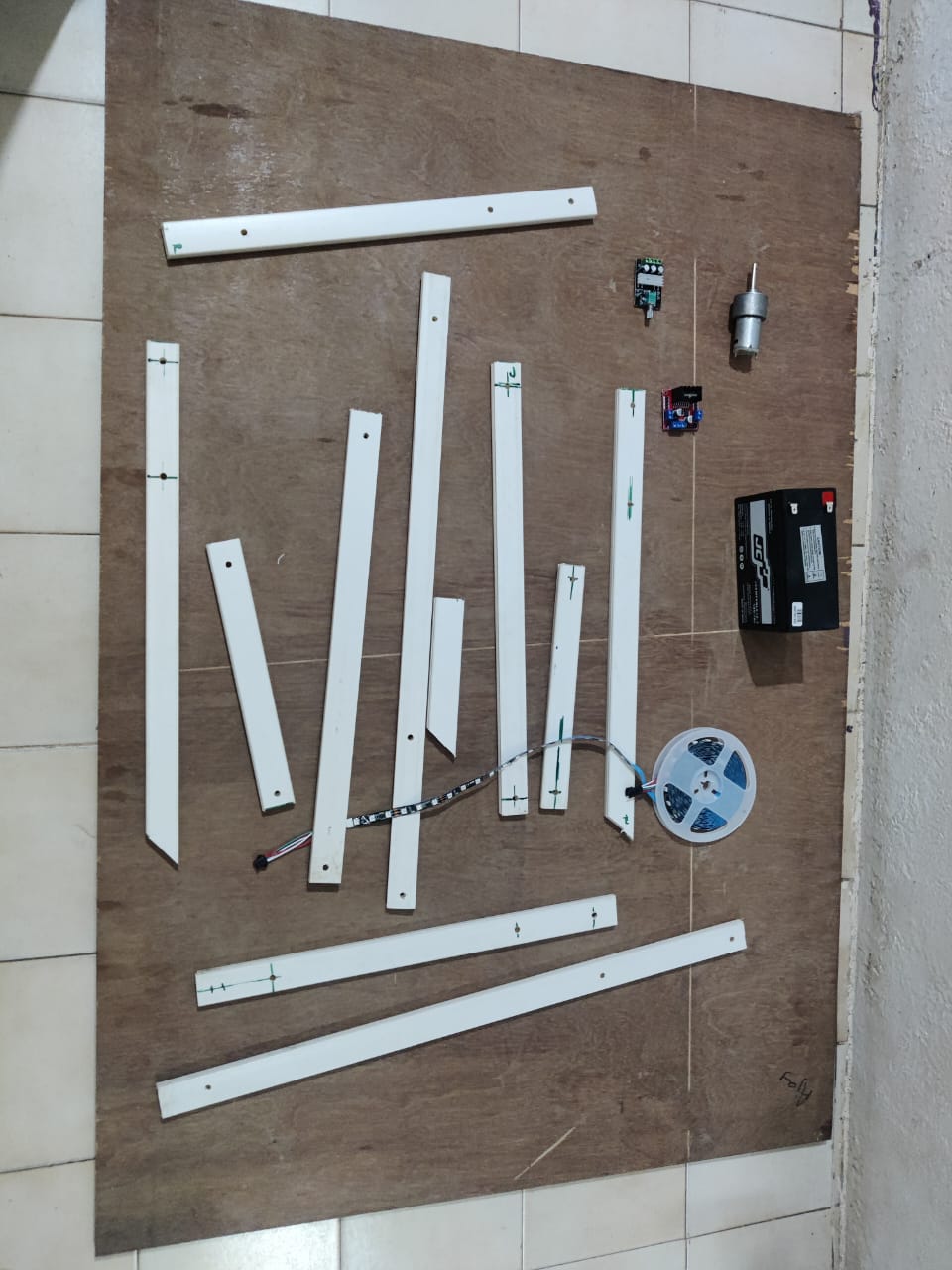
Each motor was mounted securely with wiring enclosed in the pipe for protection and neatness. Openings were also made to accommodate LED holders, ensuring the lights align with the wing design. This organized wiring method prevents tangling during motion and offers easy access for maintenance, making the system safe, functional, and visually clean.
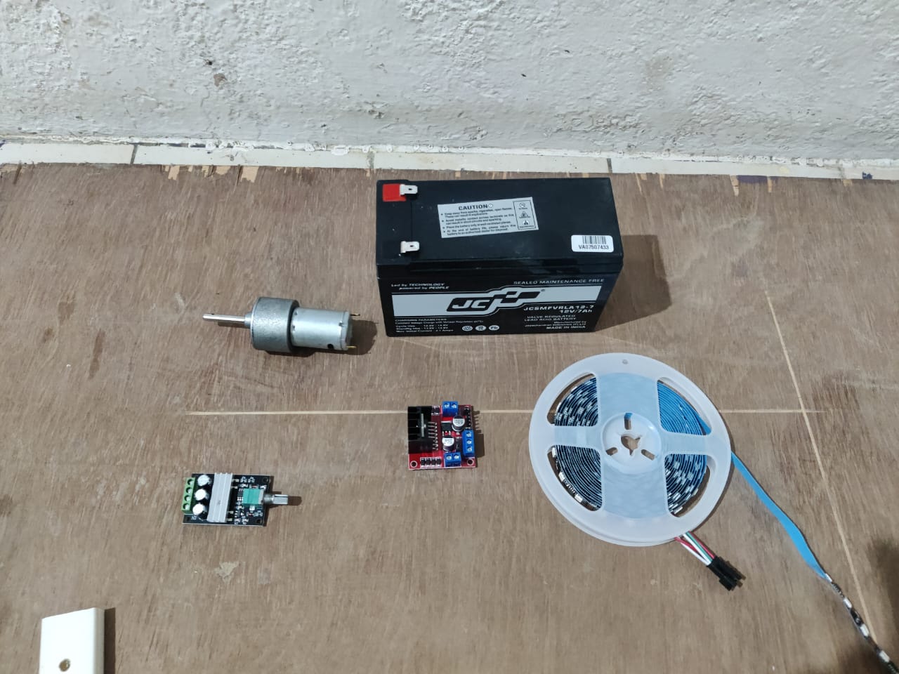
Additionally, a motor controller and speed controller were integrated to manage the actuator motors' direction and flapping speed. A 12V rechargeable battery powers the entire system, ensuring portability and consistent performance. All components were securely housed within the frame, following the 3D design for optimal space utilization and easy access.
Motor Coupling
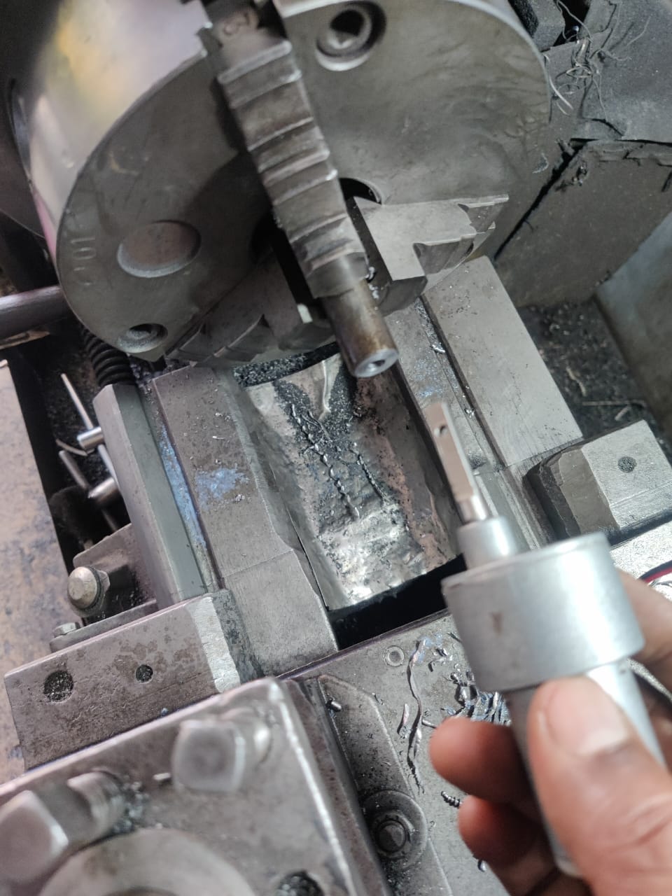
The motor coupling was custom-made using a lathe machine for precision and accuracy. A mild steel round rod was cut to a length of 2 inches, and the outer surface was turned smooth. The lathe ensured that both ends were perfectly aligned and centered for proper shaft insertion, crucial for balanced rotation and torque transmission.
Using a drill chuck mounted on the lathe tailstock, two different bore diameters were machined—6mm on one end to fit the motor shaft and 10mm on the other end for the screw rod. The depth of each bore was precisely 1 inch to ensure equal engagement. After boring, the piece was faced and chamfered for clean, burr-free edges.
Finally, two transverse holes were drilled manually on each side using a bench drill, and tapped to accommodate small bolts and nuts for locking both shafts securely. This lathe-made coupling ensures high strength, perfect alignment, and long-lasting performance.
Finalizing the Frame and Bag setup
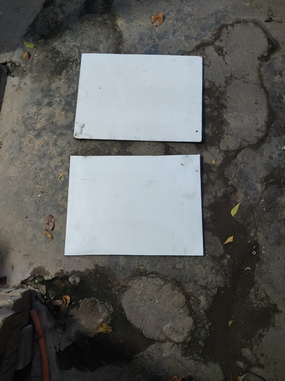
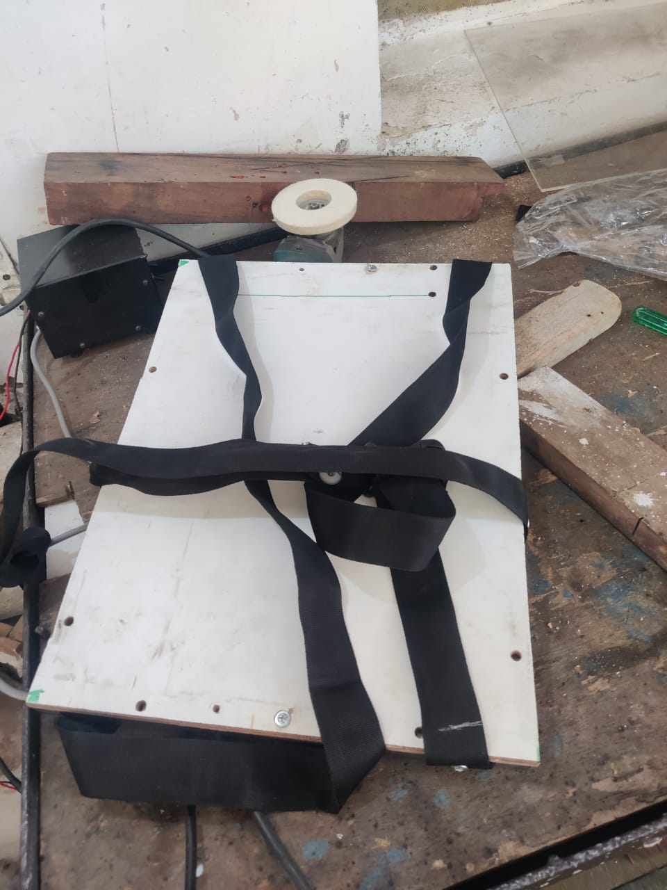
To finalize the Fantasy Flair project, the frame was enclosed for both protection and aesthetics. One side of the metal frame was covered with plywood, cut precisely to match the frame dimensions. This provided a strong, flat surface to support internal components and prevent exposure. The opposite side was enclosed using an extruded frame, also topped with plywood, but elevated to a 1-inch height to accommodate wiring, LED lights, and airflow. This setup ensures durability, protects electronics, and enhances the visual appearance. The enclosed design also simplifies portability and supports safe integration into a wearable or bag-mounted unit.
To enhance the strength and durability of the Fantasy Flair wearable setup, the ends of the shoulder straps were riveted directly into the metal frame. Riveting ensures a strong, permanent connection that can withstand the mechanical vibrations and repeated motion caused by the flapping wing mechanism. Unlike stitching or bolts, rivets distribute the load evenly, reducing the risk of tearing or loosening over time.
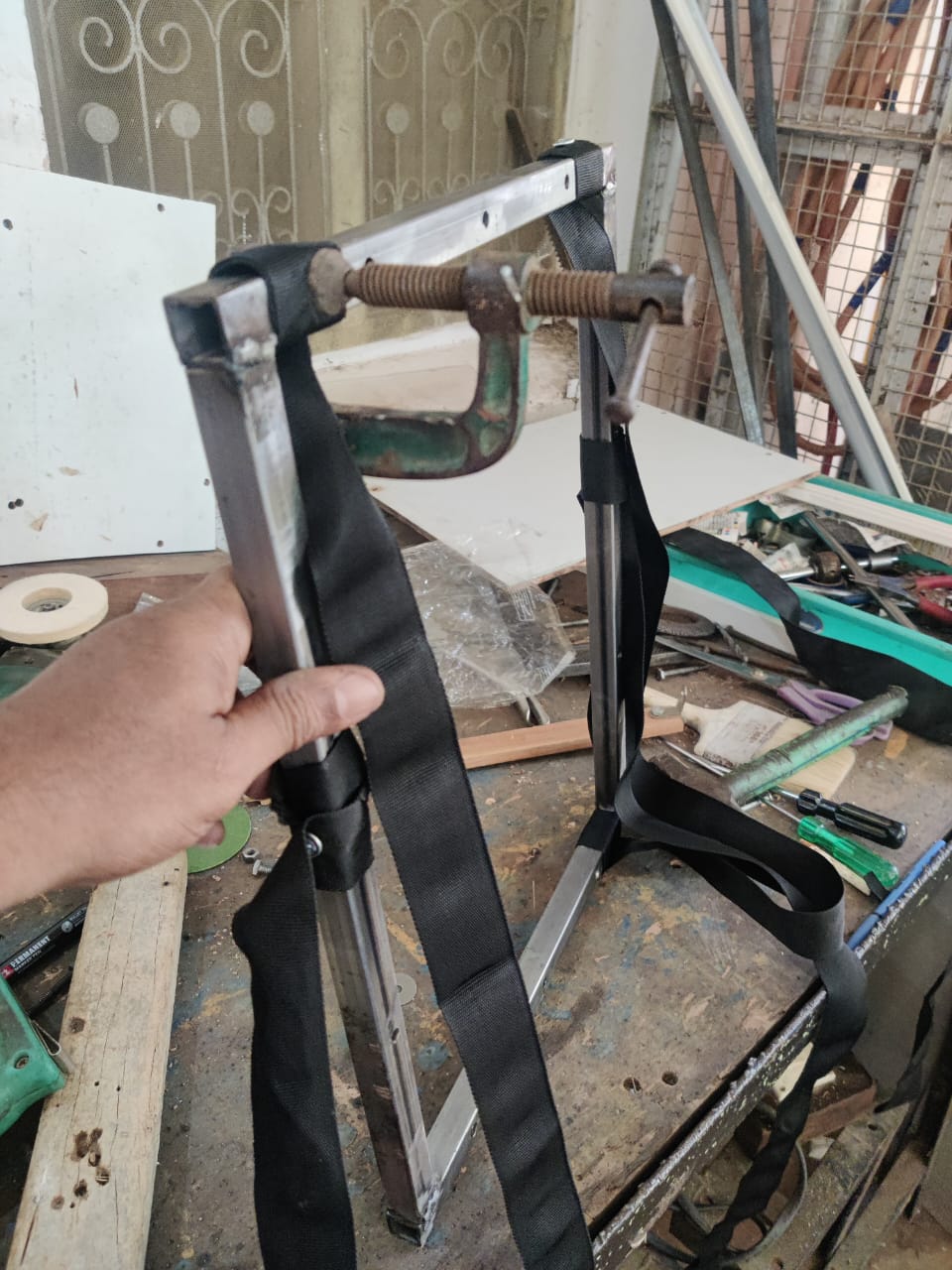
Both 1.5-inch flat black ropes were measured according to the bag size and then riveted at the top and bottom of the frame for a fixed, load-bearing support. These straps are non-adjustable, providing a firm and consistent fit during use.
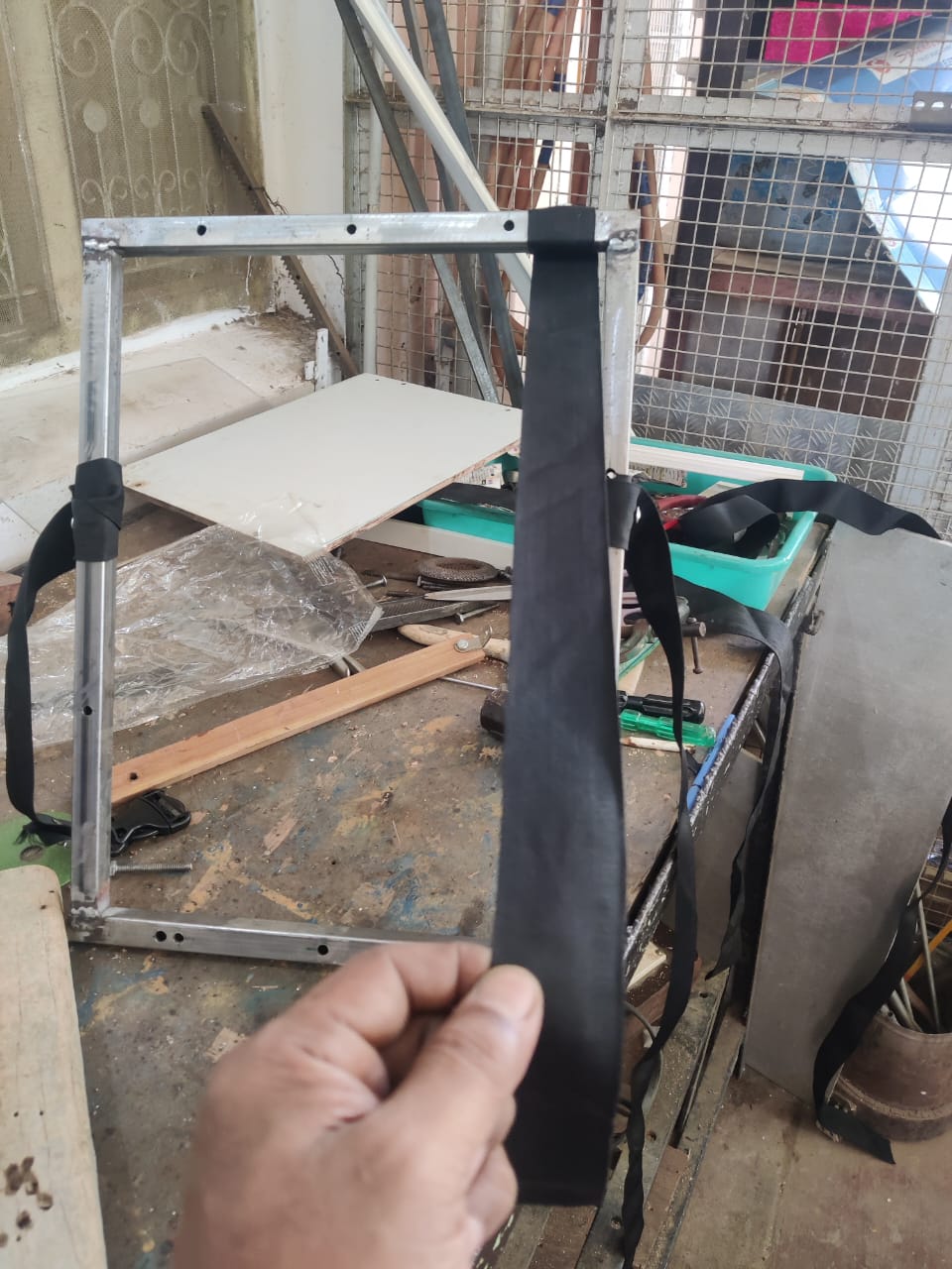
The vertical side belt, equipped with an adjustable buckle and lock, was also riveted to the frame at one end. This combination of riveted joints and adjustable locking not only improves the overall structure’s strength but also ensures reliable, long-term use for dynamic wearable applications.
Fabricating and Fixing Actuator
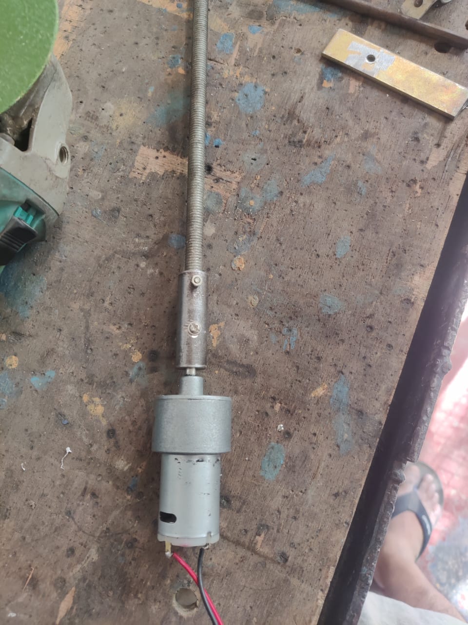
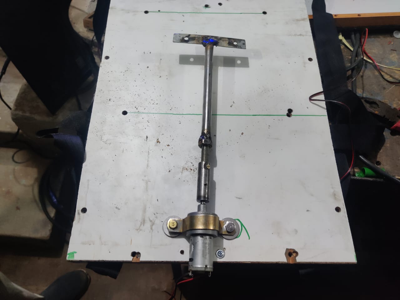
While assembling the actuator for the Fantasy Flair system, a lightweight steel pipe was found that fits freely over the 10 mm screw rod. This pipe was ideal for creating a sliding actuator component. To convert the rotary motion of the screw into linear motion, a metal nut was inserted into the pipe, aligned precisely with the screw thread. The nut and pipe were then welded together, ensuring that when the screw rotates, the pipe travels smoothly along its length, driven by the fixed nut.
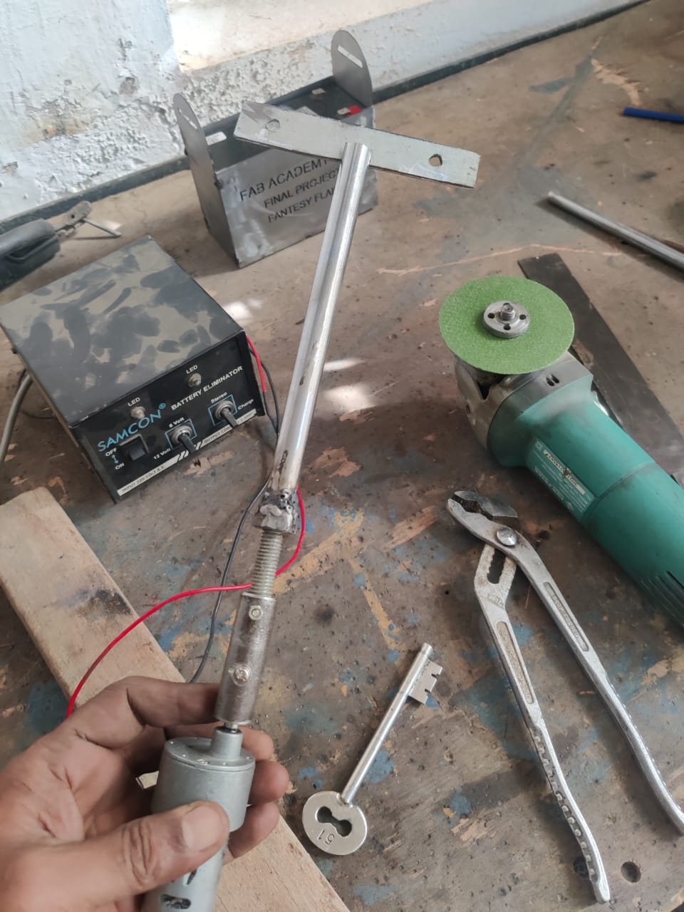
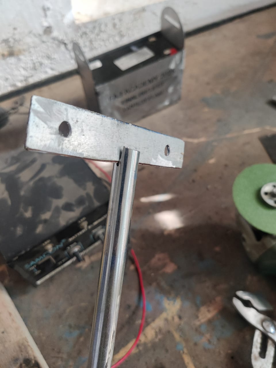
To connect the actuator to the wings, a 4-inch × 1-inch sheet metal strip was used. This strip acts as a T-connector. Two holes were drilled on each end of the strip to allow for future bolting or hinge joints. The center of the strip was welded perpendicularly to the top of the moving pipe, forming a rigid and reliable "T"-shaped bracket.
This simple yet effective fabrication allows the wings to flap smoothly with controlled motion driven by the screw actuator.
Finally, the actuator motor was fixed at the center of the plywood base using a 1-inch round plumbing fitting. This fitting securely holds only the motor body, allowing the screw rod to rotate freely without obstruction. The plumbing clamp was bolted at both ends to the plywood for a tight and rigid fit, preventing any vibration or displacement during operation.
The moving pipe, which travels along the screw rod, is connected to a T-shaped metal strip welded on top. This "T" connector is used to link the actuator to the flapping wings, allowing smooth linear motion to drive the wings up and down.
By separating the motor mount and the moving linkage, the setup ensures both mechanical stability and freedom of motion, making the flapping action efficient and aligned with the original 3D design and functionality goals of the Fantasy Flair system.
Electronics and Assembly
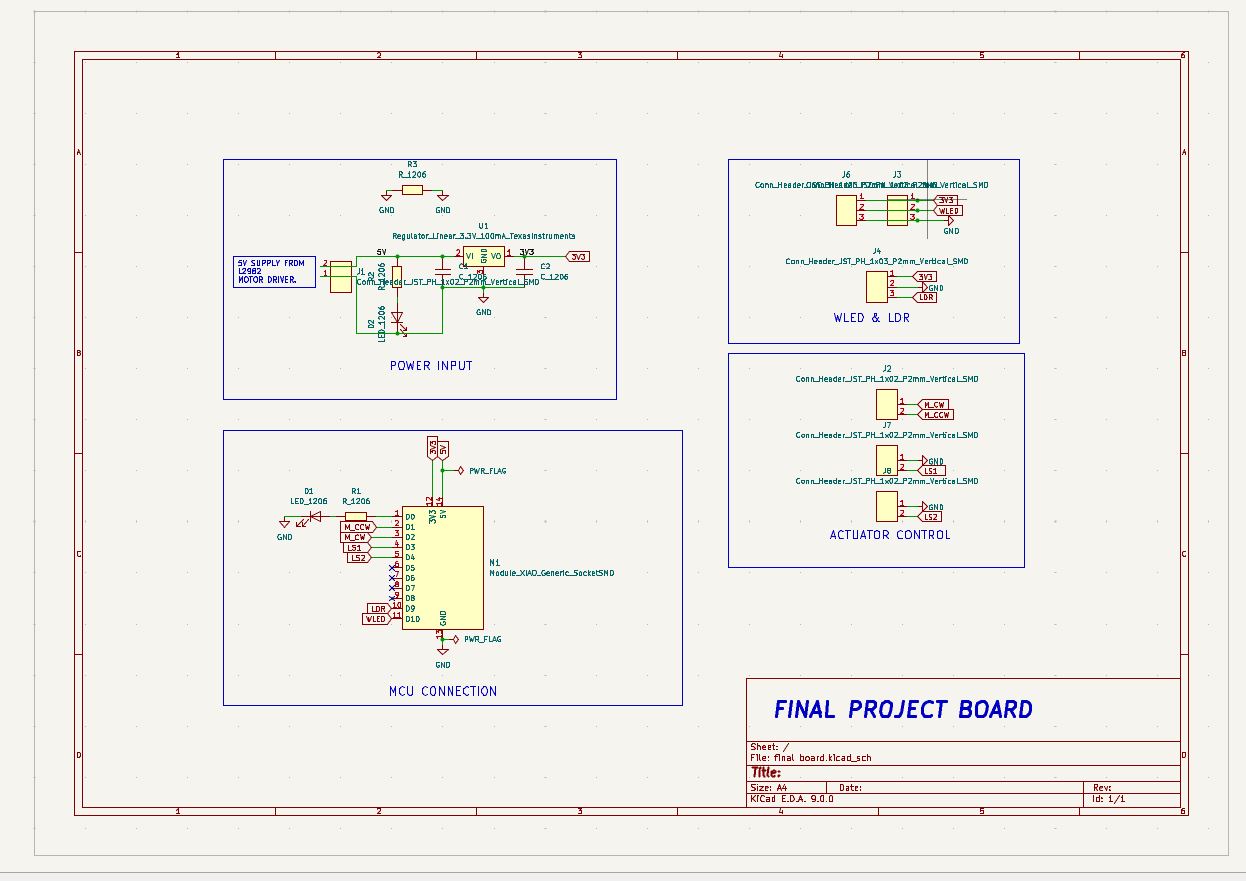
To create the final project schematic in KiCad, start by opening KiCad and creating a new project. Launch the Schematic Editor and add all required components from the symbol library, such as microcontrollers, sensors, actuators, voltage regulators, and connectors. Use the "Place Wire" tool to connect components logically. Assign proper values and labels. Run Electrical Rules Check (ERC) to verify connections. Link footprints using the "Assign Footprints" tool. Save the schematic and generate the netlist or proceed directly to PCB layout. This schematic forms the foundation for creating a well-functioning PCB for your final project.
To design the PCB in KiCad, open the PCB Editor after completing your schematic and assigning footprints. Import the netlist or use the "Update PCB from Schematic" tool to load all components. Arrange the components logically and compactly, keeping signal integrity and accessibility in mind. Define the board outline using the Edge.Cuts layer
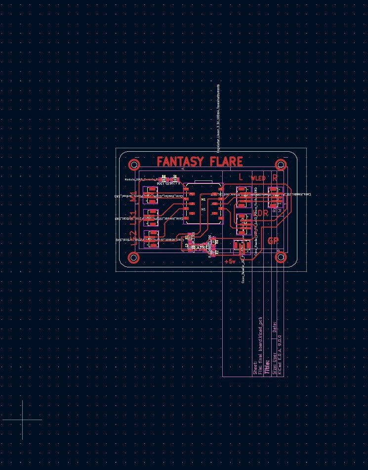
Use the Route Tracks tool to manually connect traces between components, or use auto-router plugins if preferred. Define copper zones for GND or power planes. Perform Design Rule Check (DRC) to ensure there are no errors. Finally, export Gerber files for fabrication.
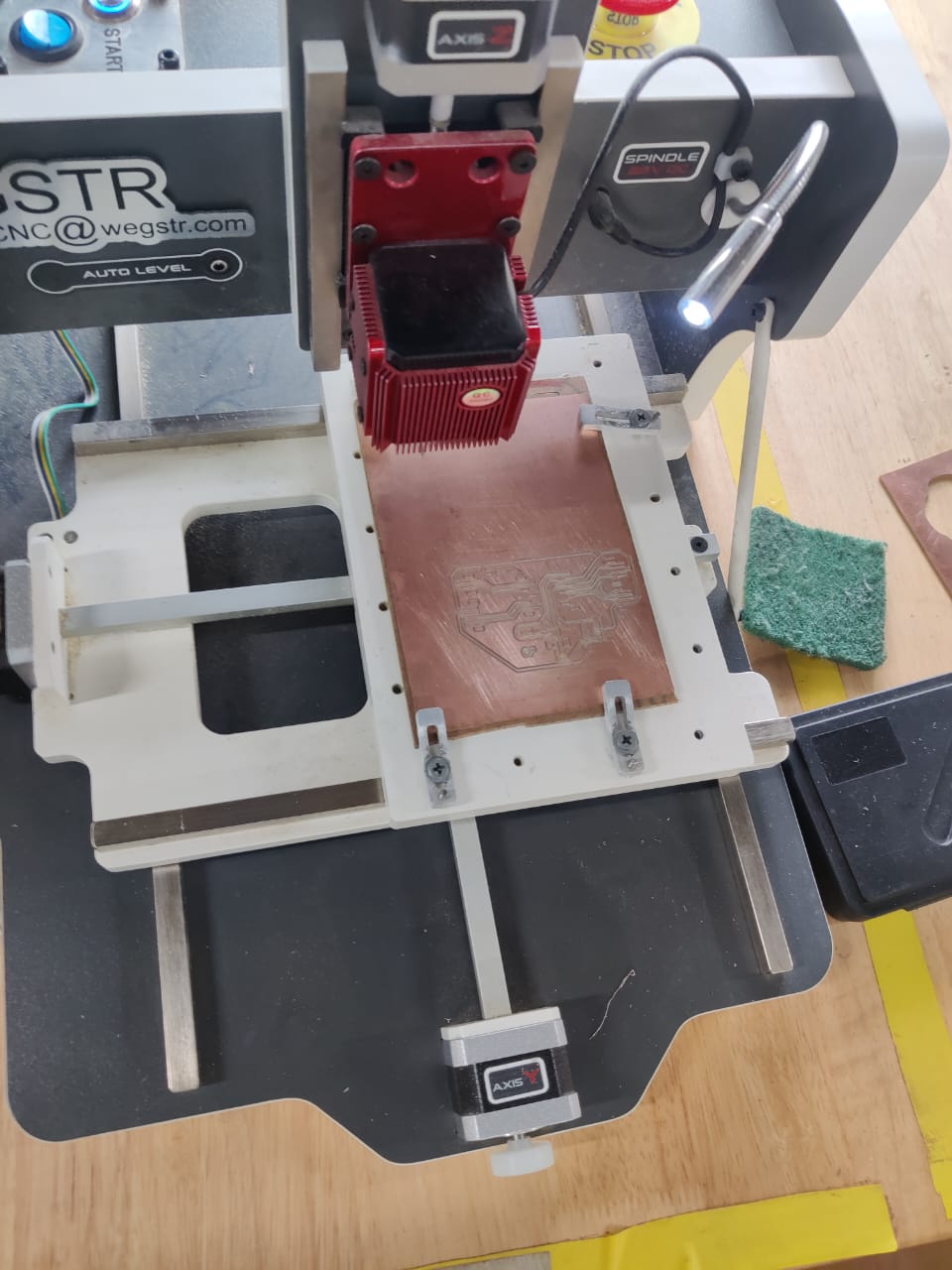
The WGSTR PCB milling machine is a desktop CNC machine designed for rapid PCB prototyping. It precisely mills copper-clad boards to create circuit traces, eliminating the need for chemical etching. Ideal for makers and labs, it supports Gerber files and offers fine detail with adjustable spindle and depth control.
The output of our PCB board for the Fantasy Flair project includes controlling four LED indicators and driving a gear motor for wing flapping. It receives Wi-Fi commands via the ESP32 module and activates outputs accordingly, providing smooth, wireless-controlled animatronic wing movements synced with colorful LED lighting effects.
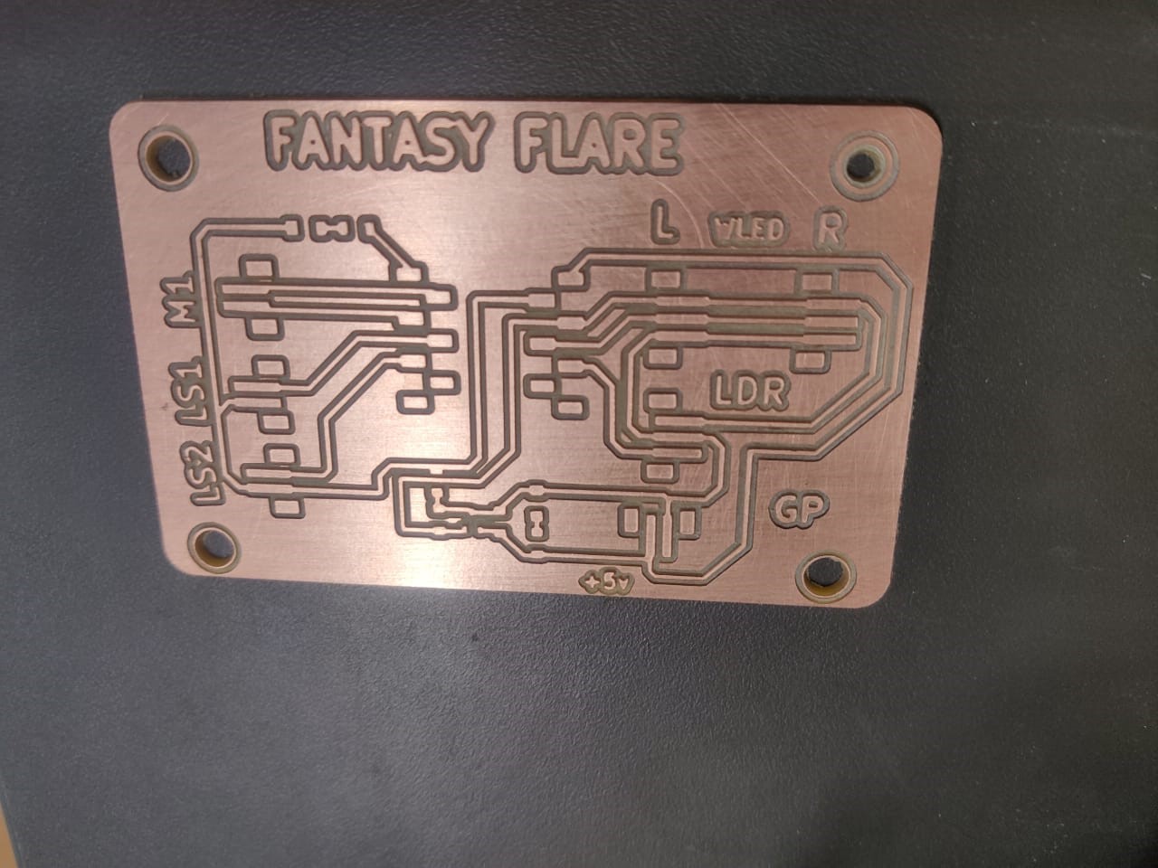
The PCB is fully fabricated by Seeed Studio, integrating the ESP32, motor controller, relay, and related components. All connections and functions were thoroughly tested and verified, ensuring reliable operation. The board successfully drives the wing motor and controls LED outputs as per the Fantasy Flair project requirements with stable performance.
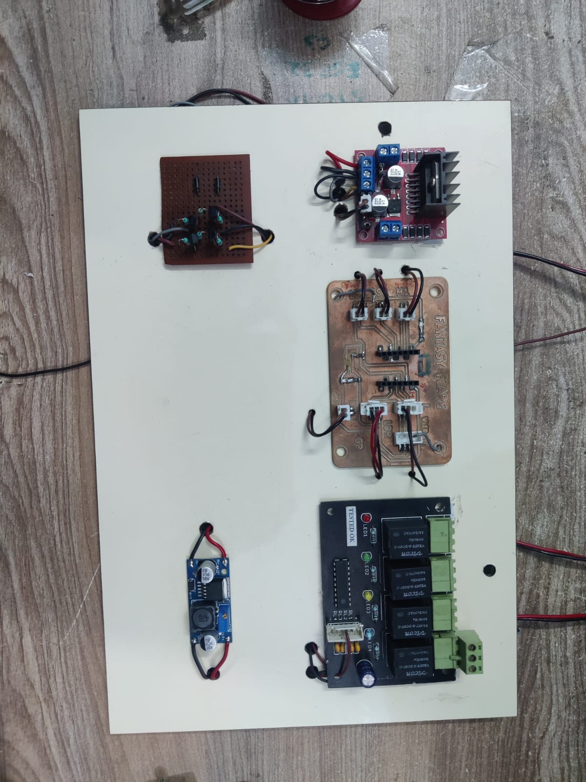
Finally, all the electronic components—ESP32, motor controller, relay, LEDs, and power supply—were integrated and securely mounted onto the Fantasy Flair system. The assembled electronics enabled seamless coordination between wireless control and mechanical motion, bringing the animatronic wings to life with synchronized lighting effects and reliable, responsive performance.
After assembling the electronics, the back plywood panel was securely screwed in place to enclose the system. This ensures that all electronic components, including the PCB, motor controller, and wiring, remain protected and safe during operation. The sturdy enclosure provides both structural support and safety for the Fantasy Flair system.
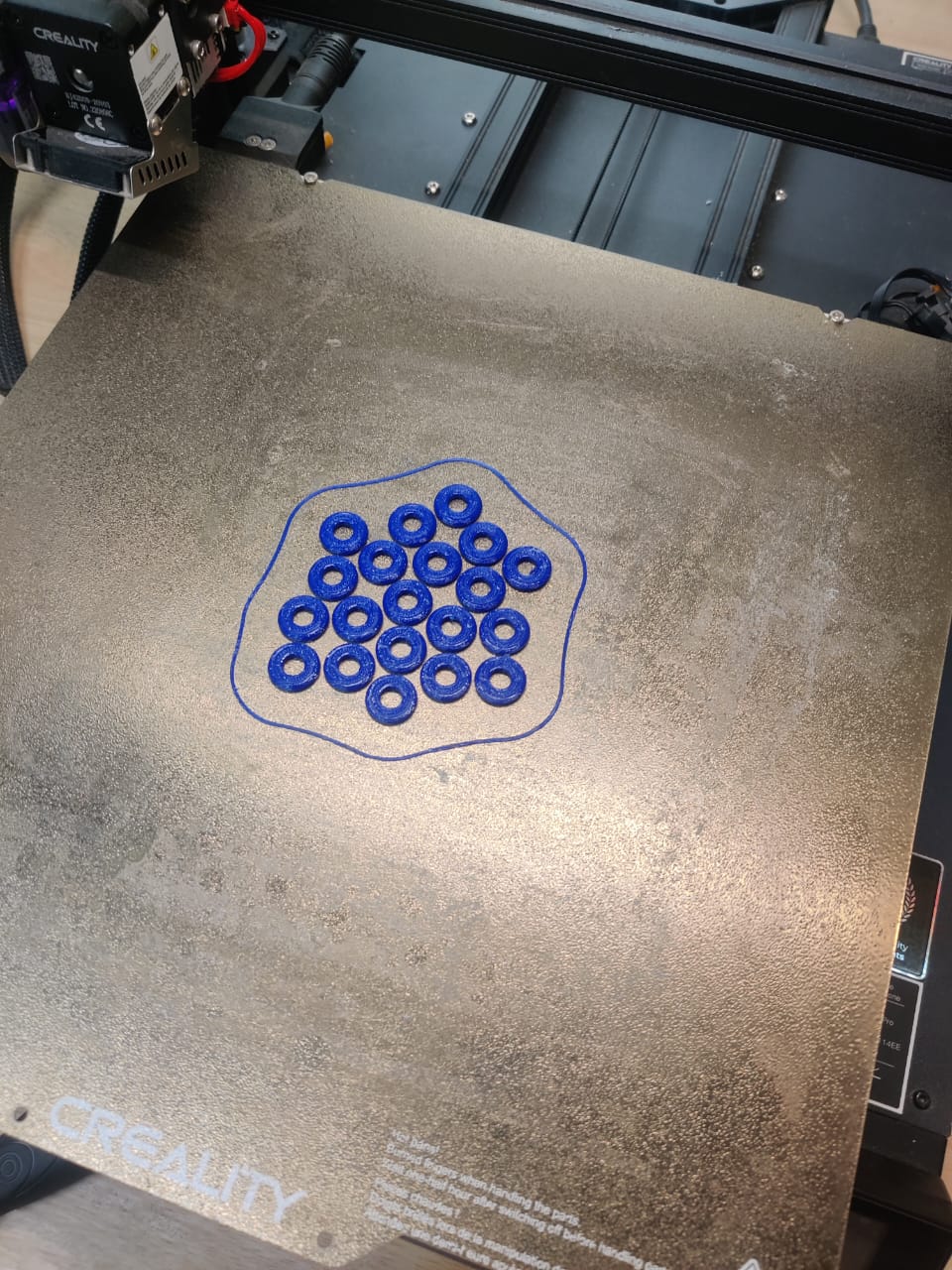
3d Printed Parts
Metal washers caused excess friction, restricting the smooth movement of the wings. To solve this, I replaced them with 3D-printed washers made from PLA, which offer low friction and a better fit. This improved the wing articulation, allowing smoother, more natural flapping motion in the Fantasy Flair system.
Battery Safety Cover
The safety cover for the battery was fabricated using 1.5mm sheet metal, precisely laser cut to the required dimensions. The design included ventilation slots and wire exit points for functionality. After cutting, the sheet was CNC bent to form a strong, enclosed structure that fits securely around the 12V, 7Ah battery used in the Fantasy Flair project.
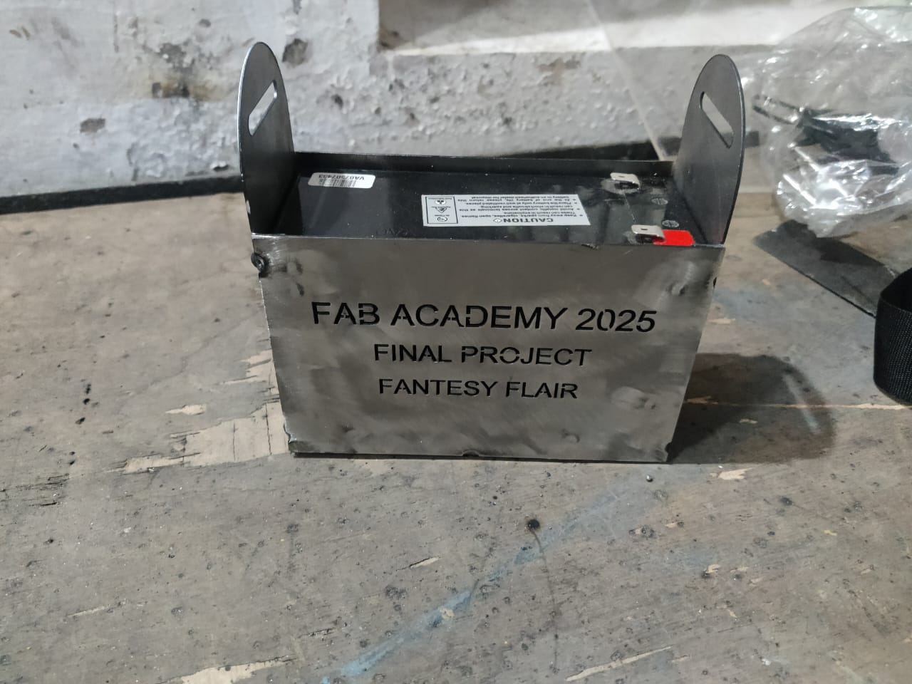
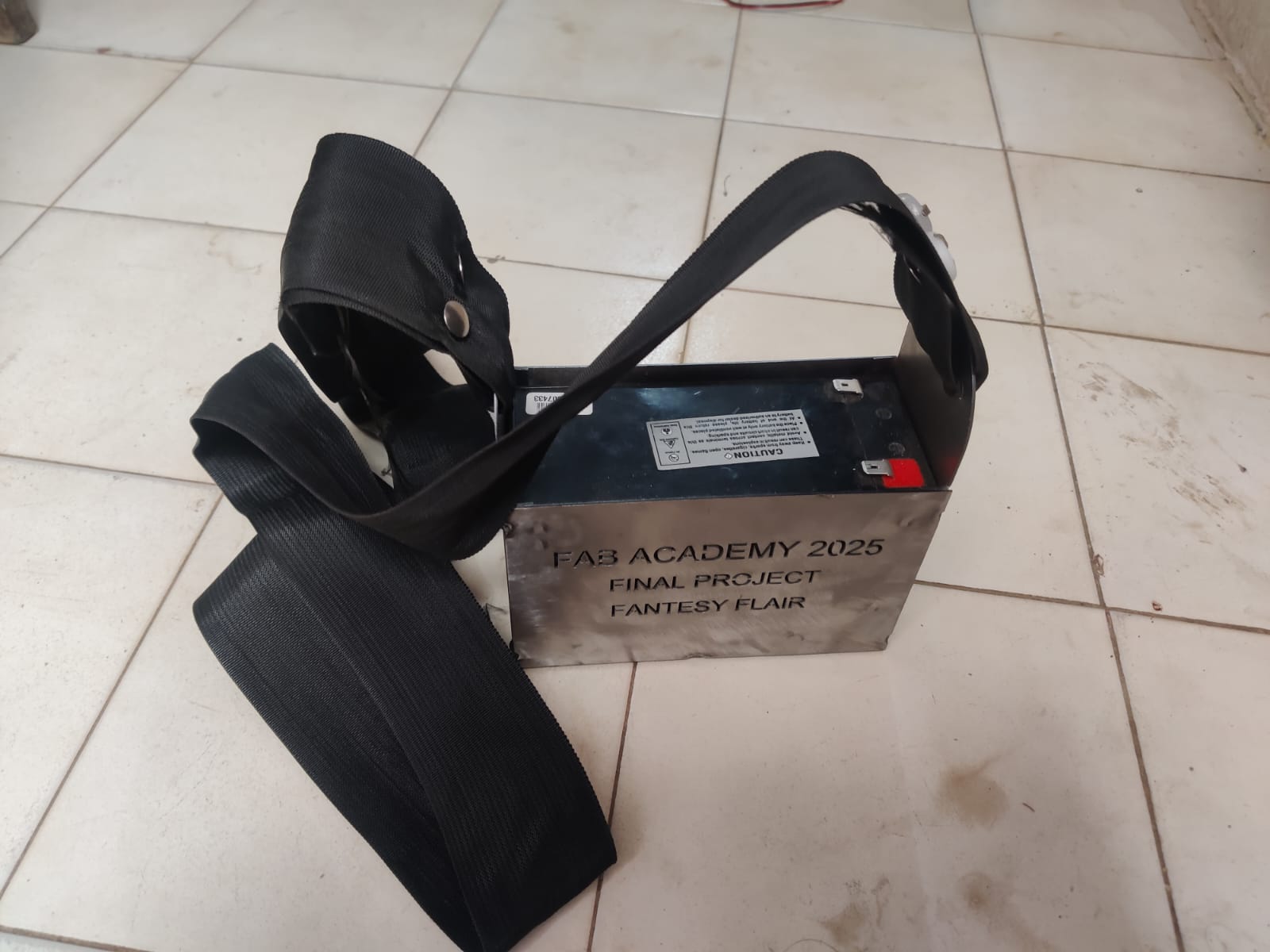
For durability and aesthetics, welding was done on two sides, creating a rigid and stable form. On one visible face, the names “Fab Academy,” “FabLab Tirchy,” and “Fantasy Flair” were engraved or cut out, giving the battery cover a professional finish and proudly showcasing the project identity. To enhance portability, the battery cover was designed like a bag, using a 1.5-inch flat bag rope securely riveted on both sides. This allows easy carrying and safe handling, making the Fantasy Flair system more mobile and user-friendly.
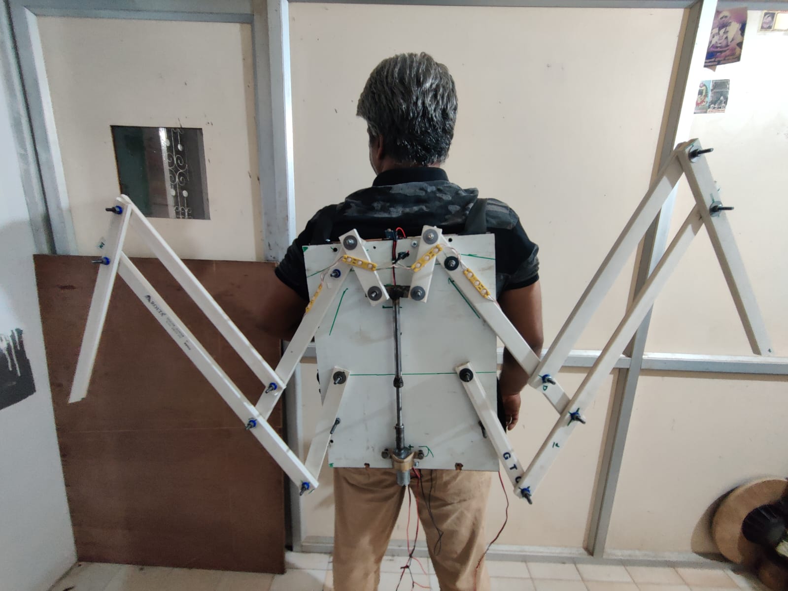
Final Mechanism Fabrication
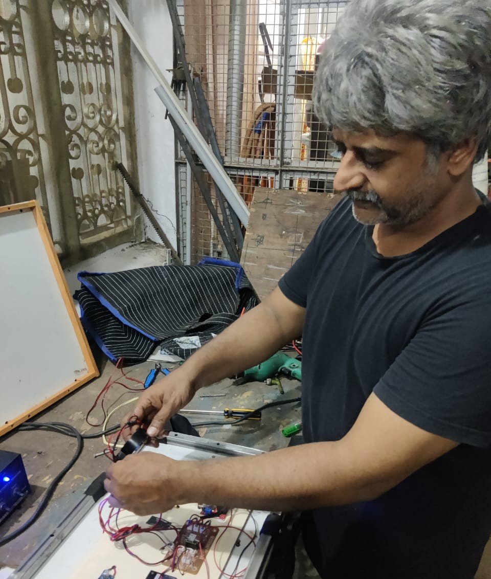
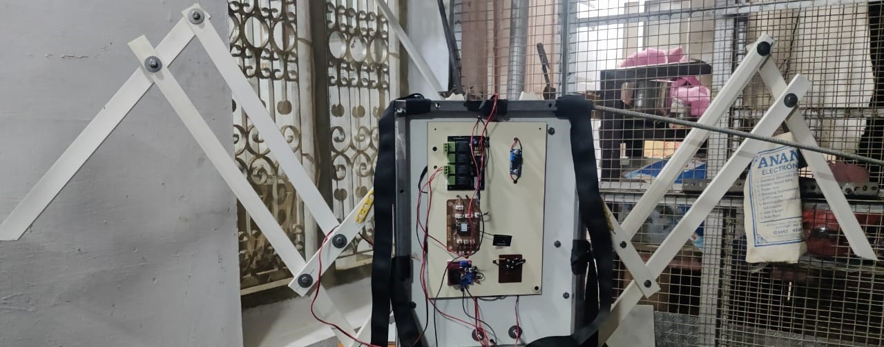
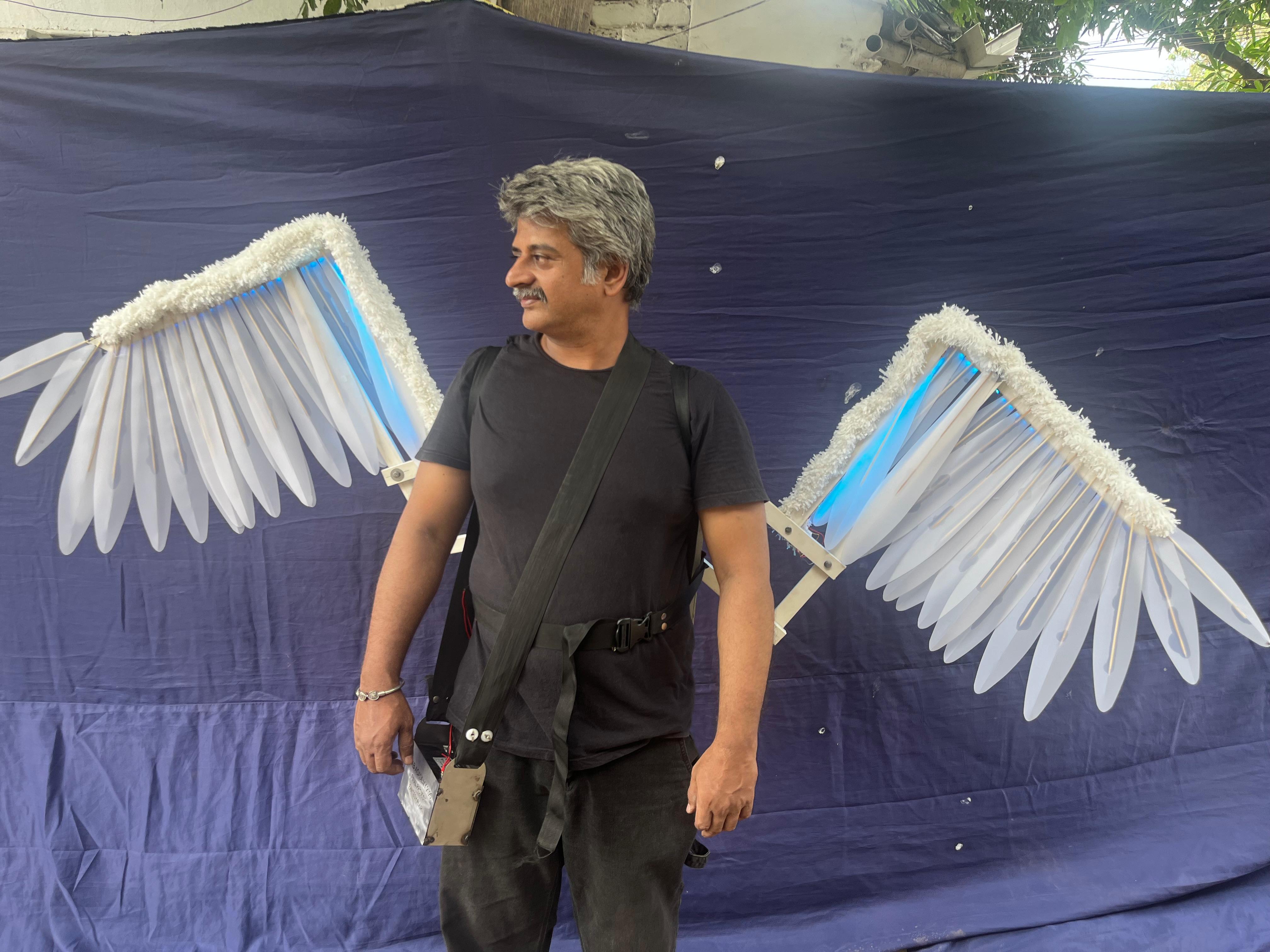
After placing the electronics inside the metal bag, it can be comfortably worn on the back using the attached strap. I connected the wings and screw actuator securely. The system is now fully assembled and functional. I conducted several trial runs, and the mechanism performed successfully as intended.
Adding features
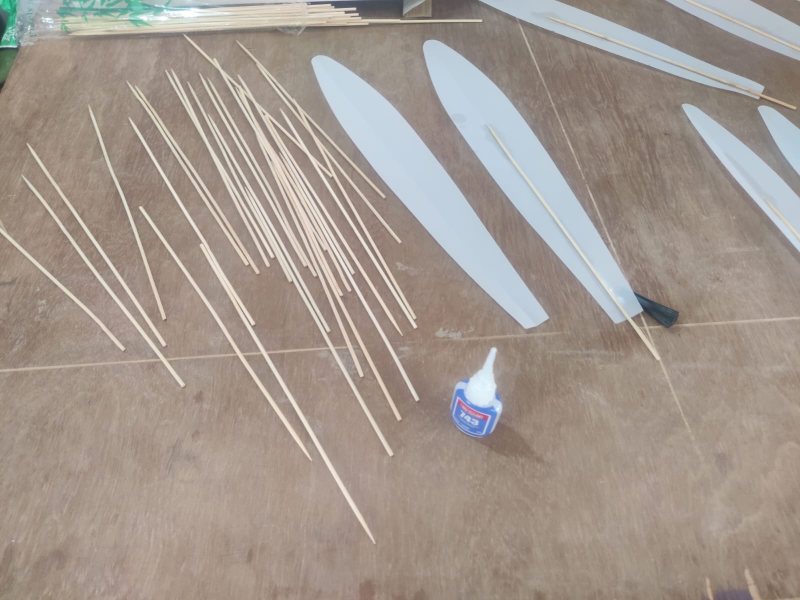
For the final touch, I added decorative feathers to enhance the visual appeal of the Fantasy Flair wings. I laser-cut tracing paper into strips of 1 foot length and 2.5-inch width. Each strip was carefully folded in half, and a noodle stick was inserted at the center using glue to create a feather-like spine. This lightweight and creative approach gave the wings a realistic, soft feather appearance, perfectly complementing the animatronic motion and aesthetic of the final project.
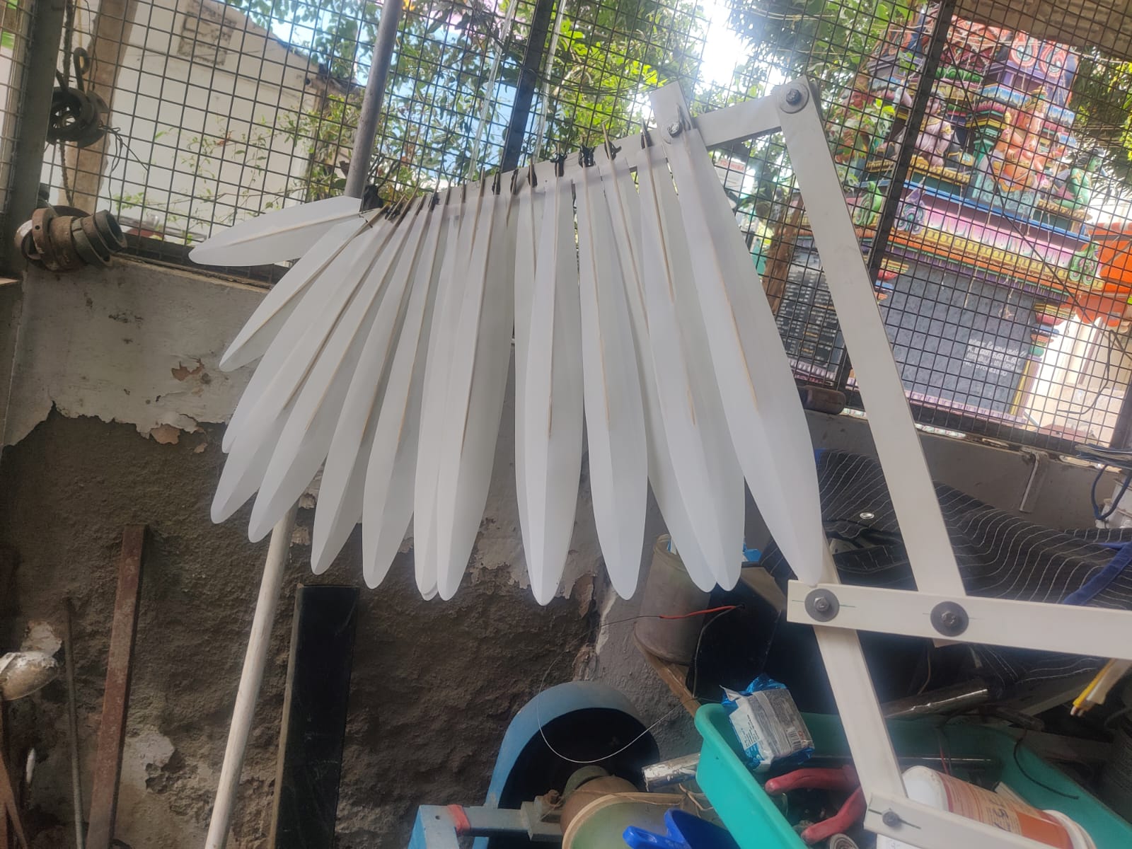
The handcrafted feathers were individually pasted using a glue gun onto the electric casing pipe wings. Each feather was carefully positioned to ensure a natural, layered look. This final step added a visually appealing, realistic feather texture to the wings, completing the Fantasy Flair project with both style and function.
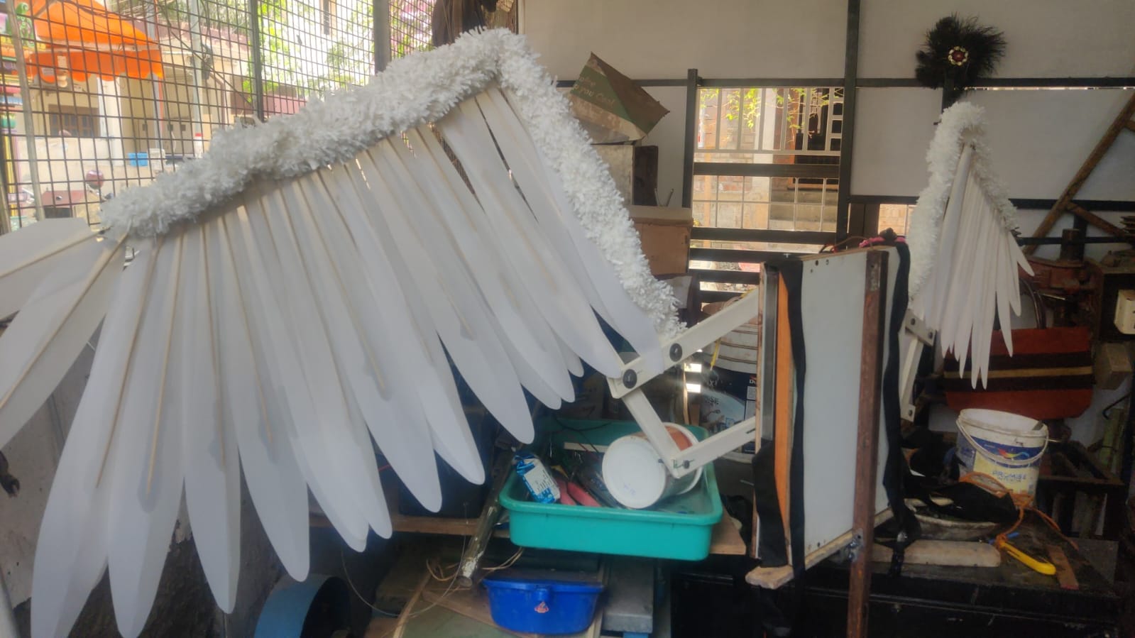
A decorative white cloth was also carefully pasted along the top line of the wing, enhancing its visual appeal. This fabric detail added elegance and contrast to the mechanical structure, blending softness with technology. It elevated the overall aesthetic, making the Fantasy Flair wings look more artistic and lifelike.
Button-Based: switch push-button as well asbluetooth Remote Switch.
Wing Motion Programming Logic
Basic Code Flow (For ESP32)
1.Fully Extended Motion (Gliding Mode)
Usually wing will be closed when remote on the the motor let the setup to move up and the relay will be off in the wing open position.
Only 2 relay
2.Flapping Motion (Dynamic Motion)
when remote on the the motor let the setup to move up and the top relay will be off in the wing open position and return to bottom relay
after cut of it move up and down continuously
System integration This part is documented in
ESP32 Wi-Fi-Based Animatronic Wing Control - Complete Arduino Code
Arduino / ESP32
// Complete Arduino Code:
#include <WiFi.h>
#include <WebServer.h>

// Wi-Fi Credentials
const char* ssid = "Redmi10T";
const char* password = "12345678";
int a = 0;

// LED pins
const int ledPins[4] = {3, 4, 8, 10}; // GPIOs for Red, Green, Blue, Pink OUTPUTS
// 2, 3 Motor Logic Input to L298 to forward and reverse direction
// 8 Bird Sound Output
// 10 WLED Output

WebServer server(80);

// HTML Page with JavaScript and CSS
const char MAIN_page[] PROGMEM = R"rawliteral(
<!DOCTYPE html>
<html>
<head>
  <title>ESP32 LED Control</title>
  <style>
    body { font-family: Arial; text-align: center; margin-top: 40px; background: #f0f0f0; }
    h1 { color: #333; }
    button {
      font-size: 18px; padding: 10px 20px; margin: 10px;
      border: none; border-radius: 8px;
      cursor: pointer; color: white;
    }
    .red { background-color: #e53935; }
    .green { background-color: #43a047; }
    .blue { background-color: #1e88e5; }
    .pink { background-color: #d81b60; }
    .off { background-color: #757575; }
  </style>
</head>
<body>
  <h1>ESP32 LED Controller</h1>
  <div>
    <button class="red" onclick="send('red/on')">FLY UP</button>
    <button class="off" onclick="send('red/off')">FLY UP OFF</button><br>
    <button class="green" onclick="send('green/on')">FLY DOWN</button>
    <button class="off" onclick="send('green/off')">FLY DOWN OFF</button><br>
    <button class="blue" onclick="send('blue/on')">FLYING</button>
    <button class="off" onclick="send('blue/off')">FLYING OFF</button><br>
    <button class="pink" onclick="send('pink/on')">LED OUT</button>
    <button class="off" onclick="send('pink/off')">LED OFF</button>
  </div>
  <script>
    function send(path) {
      fetch('/' + path)
        .then(response => response.text())
        .then(data => console.log(data));
    }
  </script>
</body>
</html>
)rawliteral";

// Web server route handling
void handleRoot() {
  server.send_P(200, "text/html", MAIN_page);
}

void setupRoutes() {
  server.on("/", handleRoot);
  server.on("/red/on", []() {
    digitalWrite(ledPins[0], HIGH); Serial.println("FLY UP");
    server.send(200, "text/plain", "Red ON");
  });
  server.on("/red/off", []() {
    digitalWrite(ledPins[0], LOW); Serial.println("FLY UP OFF");
    server.send(200, "text/plain", "Red OFF");
  });
  server.on("/green/on", []() {
    digitalWrite(ledPins[1], HIGH); Serial.println("FLY DOWN");
    server.send(200, "text/plain", "Green ON");
  });
  server.on("/green/off", []() {
    digitalWrite(ledPins[1], LOW); Serial.println("FLY DOWN OFF");
    server.send(200, "text/plain", "Green OFF");
  });
  server.on("/blue/on", []() {
    digitalWrite(ledPins[2], HIGH); Serial.println("FLYING"); a = 1;
    server.send(200, "text/plain", "Blue ON");
  });
  server.on("/blue/off", []() {
    digitalWrite(ledPins[2], LOW); Serial.println("FLYING OFF"); a = 0;
    server.send(200, "text/plain", "Blue OFF");
  });
  server.on("/pink/on", []() {
    digitalWrite(ledPins[3], HIGH); Serial.println("LED OUT");
    server.send(200, "text/plain", "Pink ON");
  });
  server.on("/pink/off", []() {
    digitalWrite(ledPins[3], LOW); Serial.println("LED OFF");
    server.send(200, "text/plain", "Pink OFF");
  });
}

void setup() {
  Serial.begin(115200);
  for (int i = 0; i < 4; i++) {
    pinMode(ledPins[i], OUTPUT); digitalWrite(ledPins[i], LOW);
  }
  pinMode(5, INPUT);  // UP STOP Switch
  pinMode(6, INPUT);  // DOWN STOP Switch
  pinMode(9, INPUT);  // LDR Sensor

  WiFi.begin(ssid, password);
  Serial.print("Connecting to WiFi");
  while (WiFi.status() != WL_CONNECTED) {
    delay(500); Serial.print(".");
  }
  Serial.println("\nWiFi connected. IP address: ");
  Serial.println(WiFi.localIP());

  setupRoutes();
  server.begin();
}

void loop() {
  if (digitalRead(5)==LOW) {
    digitalWrite(ledPins[0], LOW); Serial.println("FLY UP OFF");
    server.send(200, "text/plain", "Red OFF");
  }
  if (digitalRead(6)==LOW) {
    digitalWrite(ledPins[1], LOW); Serial.println("FLY DOWN OFF");
    server.send(200, "text/plain", "Green OFF");
  }
  if (digitalRead(9)==HIGH) {
    digitalWrite(10, HIGH);
  } else {
    digitalWrite(10, LOW);
  }

  if (a == 1) {
    if (digitalRead(5)==LOW) {
      digitalWrite(ledPins[0], LOW); digitalWrite(ledPins[1], HIGH);
      Serial.println("FLY UP OFF"); Serial.println("FLY DOWN");
      server.send(200, "text/plain", "Red OFF");
      server.send(200, "text/plain", "Green ON");
    }
    if (digitalRead(6)==LOW) {
      digitalWrite(ledPins[1], LOW); digitalWrite(ledPins[0], HIGH);
      Serial.println("FLY DOWN OFF"); Serial.println("FLY UP");
      server.send(200, "text/plain", "Green OFF");
      server.send(200, "text/plain", "Red ON");
    }
  }
  server.handleClient();
}
Bill of Material
| Product Name | Description | Price | Quantity | Total Price | |
|---|---|---|---|---|---|
| Square Pipe (Mild Steel) | 10 feet | ₹500 | 1 | ₹500 | |
| Motor to screwrod Coupler | 16mm | ₹377 | 1 | ₹377 | |
| DC Motor | 12V 30RPM | ₹350 | 1 | ₹350 | |
| Battery | 12V 7 amps | ₹750 | 1 | ₹750 | |
| Battery case in sheet metal | lasercut charges | ₹500 | 1 | ₹500 | |
| Wire | 14/36 Multi Color | ₹100 | 1 | ₹100 | |
| Limit Switch | DC Motor Cutoff | ₹100 | 2 | ₹200 | |
| Motor Driver | Manual Direction | ₹180 | 1 | ₹180 | |
| Motor fixture | 1.5inch Pipe clamp | ₹10 | 1 | ₹10 | |
| Wing Materials | Electric casing pipe 20 feet. | ₹160 | 1 | ₹160 | |
| Rgb Led | 10feet | ₹881 | 1 | ₹881 | |
| bag belt,lock,rivit etc | (total set) | ₹350 | 1 | ₹350 | |
| 2 inch,1 inch bolt,nut,washer | 100grams | ₹80 | 1 | ₹80 | |
| Grand Total | ₹4,438 | ||||
Reference Video
Project Slide