Embedded Programming
Home ← →
Objective of this Week
- Browse through the datasheet for our microcontroller
- Compare the performance and development workflows for other architectures
Datasheet
A Datasheet is a detailed document provided by the manufacturer that contains essential information about the microcontroller's specifications, features, and usage guidelines. Some of it includes as,
- Electrical Characteristics – Operating voltage, power consumption, and current ratings.
- Pin Configuration – Details on each pin’s function, including power, input/output, and special-purpose pins.
- Memory Details – Information on Flash memory, RAM, and EEPROM for code and data storage.
- Peripherals and Interfaces – Built-in modules like ADCs, timers, PWM, UART, SPI, and I2C for communication and control.
- Clock and Timing Information – Internal and external clock sources, oscillators, and timers.
- Programming and Debugging – Supported programming methods, bootloader options, and debugging interfaces.
- Performance and Operating Conditions – Processing speed, power modes, and environmental limits.
How it helps?
Component Selection – Helps engineers choose the right microcontroller for their application.
Circuit Design – Ensures correct connections and power requirements.
Firmware Development – Provides register addresses, memory maps, and peripheral control details for writing code.
Troubleshooting – Helps diagnose issues related to power, communication, or functionality.
Microcontrollers
A Microcontroller (MC, UC, or μC) or microcontroller unit (MCU) is a compact computer integrated into a single chip. It includes one or more processor cores (CPUs), memory, and programmable input/output (I/O) peripherals. The chip also contains program memory, such as NOR flash, OTP ROM, or ferroelectric RAM, along with a small amount of RAM. Unlike microprocessors, which are used in personal computers with multiple external components, microcontrollers are specifically designed for embedded applications.
Features:
- Processor (CPU) – Executes instructions and controls operations.
- Memory – Stores program code (Flash) and temporary data (RAM).
- Input/Output Ports (I/O) – Interfaces with external components like sensors, motors, and LEDs.
- Communication Interfaces – Supports protocols like UART, SPI, and I2C for data exchange.
- Timers and PWM – Used for task scheduling and controlling devices like motors.
- Analog-to-Digital Converter (ADC) – Converts analog signals to digital values.
- Low Power Modes – Optimized for battery-powered applications
Types:
- 8-bit MCUs (example - ATmega328) – Simple applications like automation and IoT.
- 16-bit MCUs (example - MSP430) – Medium-complexity applications like motor control
- 32-bit MCUs (example - STM32, ESP32) – High-performance applications like robotics and AI-based systems.
In this weekly assignment we are planning to do understanding of ESP32 Microcontroller.
ESP32
The ESP32 is a powerful Wi-Fi and Bluetooth-enabled microcontroller developed by Espressif Systems. It features a dual-core 32-bit Xtensa LX6 processor, running up to 240 MHz, with 520 KB SRAM and 4 MB flash memory (varies by model). It supports Wi-Fi (802.11 b/g/n), Bluetooth 4.2/BLE, GPIOs, ADC, DAC, SPI, I2C, UART, and PWM. Known for its low power consumption and high performance, it is widely used in IoT, robotics, automation, and embedded systems.
| Feature | Description |
| Digital Pins | Works as on/off switches to control LEDs, sensors, and motors. |
| Analog Pins | Reads varying voltage levels, useful for sensors like temperature and light sensors. |
| PWM Pins | Simulates analog output by quickly switching on/off, used for dimming LEDs or controlling motor speed. |
| I2C Interface | Allows multiple devices to communicate using two wires (SDA, SCL), commonly used for sensors and displays. |
| UART Interface | Enables serial communication with computers, microcontrollers, or other peripherals. |
| SPI Interface | High-speed communication protocol for connecting peripherals like SD cards and displays. |
| Wi-Fi & Bluetooth | Built-in connectivity for IoT applications, supporting both Wi-Fi and Bluetooth (BLE). |
| Touch Pins | Special pins that detect touch input, useful for touch-sensitive applications. |
| DAC (Digital-to-Analog Converter) | Converts digital signals to true analog output, unlike PWM. |
| Deep Sleep Mode | Power-saving mode to reduce energy consumption, ideal for battery-powered projects. |
Specification:
| Item | Value |
| CPU | Dual-core Tensilica Xtensa LX6 processor (up to 240 MHz) |
| Flash Memory | Varies (External SPI Flash, typically 4MB–16MB) |
| SRAM | 520KB |
| Digital I/O Pins | 34 |
| Analog I/O Pins | 18 (ADC) |
| PWM Pins | Available on most digital pins |
| I2C Interface | 2 |
| SPI Interface | 4 |
| UART Interface | 3 |
| Wi-Fi | 802.11 b/g/n (2.4 GHz) |
| Bluetooth | Bluetooth 4.2 + BLE |
| Power Supply & Downloading Interface | Type-C / Micro USB (depends on the board) |
| Power | 3.3V DC |
| Dimensions | Varies by board (ESP32-WROOM: 18×25.5×3.1mm) |
| Programming Language | Arduino, MicroPython, ESP-IDF |
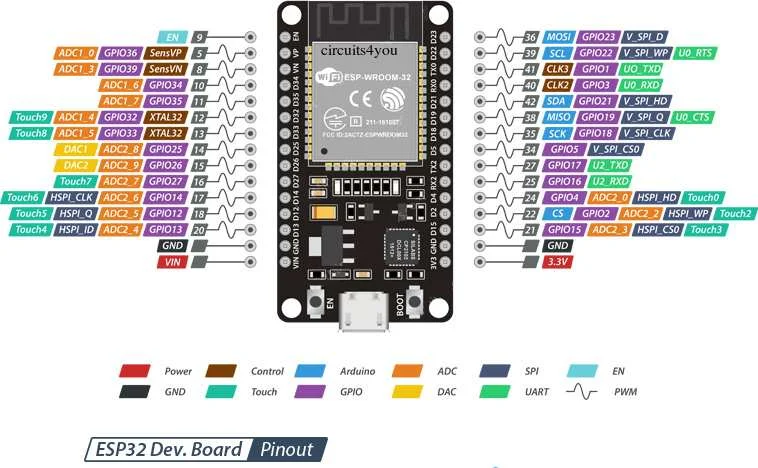
Pinout reference for ESP32:
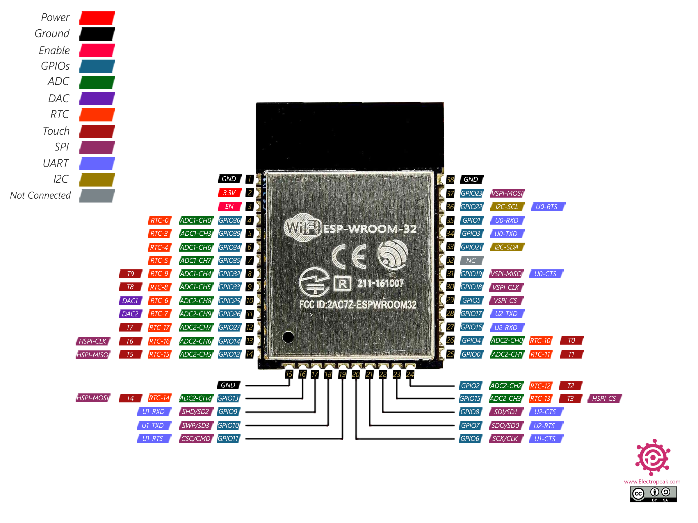
Pin Description:
| Name | Description |
| GPIOx | General-purpose digital input/output (I/O) pins. Some support internal pull-up/down resistors, PWM, and peripheral functions. |
| ADCx | Analog-to-Digital Converter (ADC) pins, used for measuring analog signals. ESP32 has multiple ADC channels with 12-bit resolution. |
| DACx | Digital-to-Analog Converter (DAC) pins, capable of producing analog voltages. Two DAC channels are available. |
| HSPIx / VSPIx | Hardware SPI interfaces for high-speed serial communication. ESP32 supports multiple SPI buses. |
| I2C SDA / SCL | I2C interface for communication with sensors and peripherals. Any GPIO can be configured as I2C. |
| UARTx TX/RX | Universal Asynchronous Receiver-Transmitter (UART) for serial communication. ESP32 supports multiple UART ports. |
| PWMx | Pulse Width Modulation (PWM) capable GPIOs, used for motor control, LED dimming, etc. |
| EN (Enable) | Chip enable pin. High to activate the chip, low to disable it and enter low power mode. |
| BOOT / IO0 | Used for entering the bootloader mode during programming. Pulled low during flashing. |
| GND | Ground connection. Required for circuit reference. |
| VCC (3.3V) | Main power supply input (3.3V). ESP32 operates at 3.3V logic levels. |
| 5V (USB VBUS) | Provides 5V from the USB input, often used to power external components. |
| VP / VN | Capacitive touch sensor input pins that also function as ADC inputs. |
| RTS / CTS | Request to Send (RTS) and Clear to Send (CTS) flow control signals for UART communication. |
| EXT_RSTB | External reset pin. Pulling low resets the ESP32. |
ESP32 Datasheet - Link
Comparison of Microcontrollers
We compare the ESP32 with ESP8266,
| Parameters | ESP32 | ESP8266 |
| Microcontroller | ESP32 | ESP8266 |
| Core | Dual core | Single core |
| Architecture | 32-bit LX6 (600 DMIPS) | 32-bit LX106 |
| Clock Speed | Up to 240MHz | Up to 160MHz |
| Operating Voltage | 3.3V | 3.3V |
| GPIO Voltage | 3.3V | 3.3V |
| Digital Pins | 36 | 16 |
| PWM Pins | 32 | 16 |
| Analog Pins | 15 | 1 |
| SPI/I2C/UART/I2S | 4/2/2/2 | 2/1/2/2 |
| Wi-Fi | Yes | Yes |
| Bluetooth | Yes | No |
| Built-in Sensors | Touch, Temperature, Hall Effect | No |
| Programming Languages | Arduino IDE, C/C++, MicroPython | Arduino IDE, C/C++, MicroPython, JavaScript |
| On-board Programming LED | D2 pin | D0 pin |
| Flash | 4MB | 4MB |
| RAM | 520KB | 128KB |
| EEPROM | No | 520B |
| Advantages | Best for IoT projects, supports Wi-Fi & Bluetooth, more GPIOs, better performance | Best for basic IoT projects, lower power consumption |
Conclusion
- ESP32 is ideal for advanced IoT projects requiring high processing power, dual-core performance, Wi-Fi, Bluetooth, and multiple peripherals. It suits applications like smart home automation, industrial IoT, and real-time data processing.
- ESP8266 is a cost-effective choice for basic IoT applications with Wi-Fi connectivity. It is suitable for simple web servers, remote monitoring, and home automation projects where Bluetooth and high-performance processing are not needed.
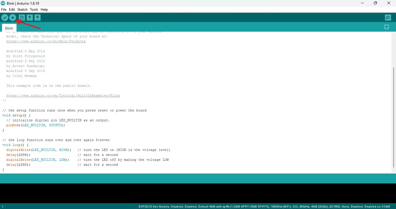
Arduino IDE
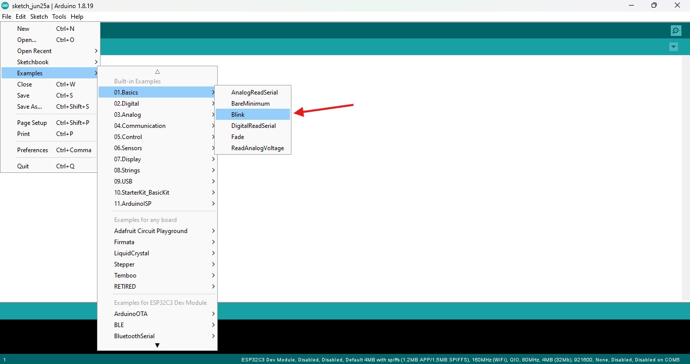
Gayathri did the LED blink by using the Arduino Board in Arduino IDE
Dowloaded the Arduino IDE and open it, navigate File>Examples>Basic>Blink
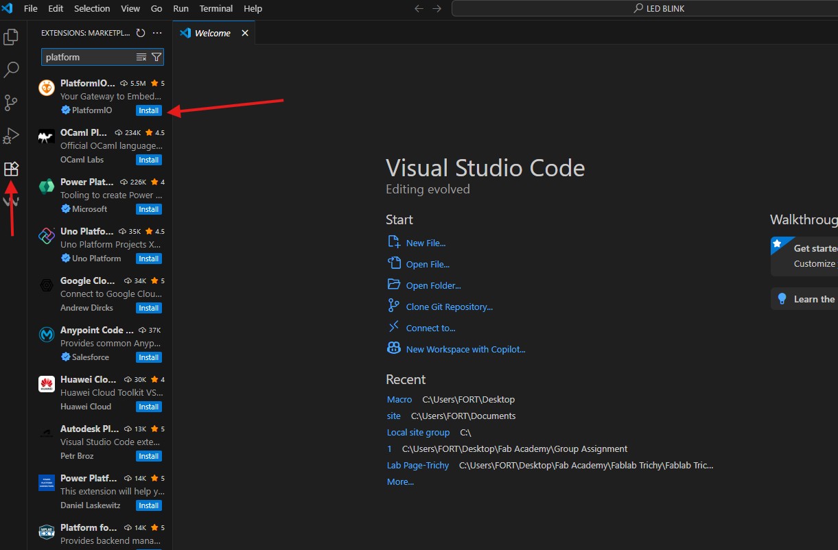
Visual Studio Code (VS Code)
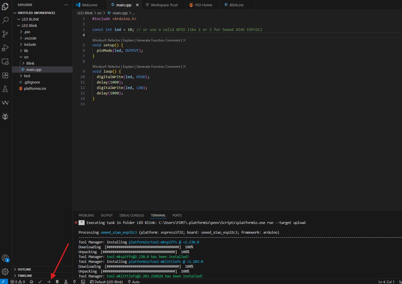
I used the VS code for the Seeed studio ESP32C3 board LED blink
I download it from the online - VS Code
After opening it and we need to install the extension name PlatformIO which is used as IDE in Visual Studio Code
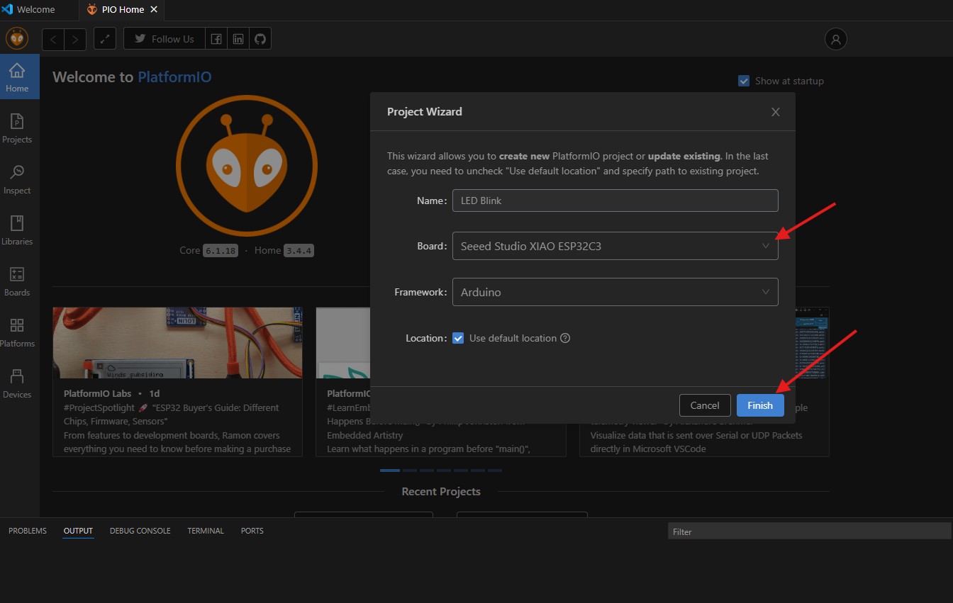
Create the new project to do the LED blink
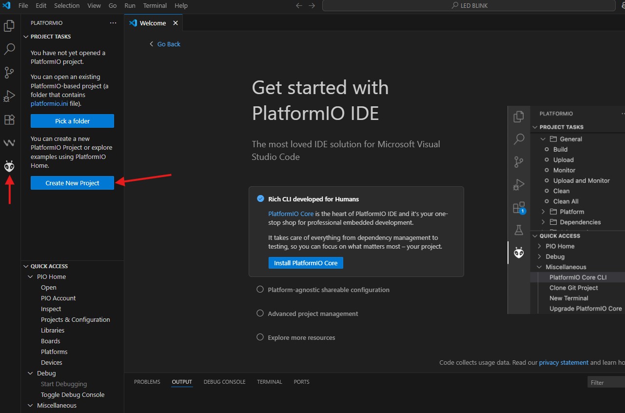
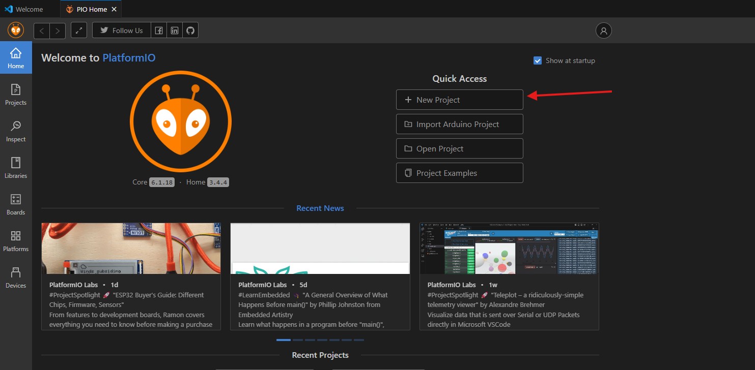
Select the right microcontroller for your work
I take the basic LED blink code from the seeed studio website
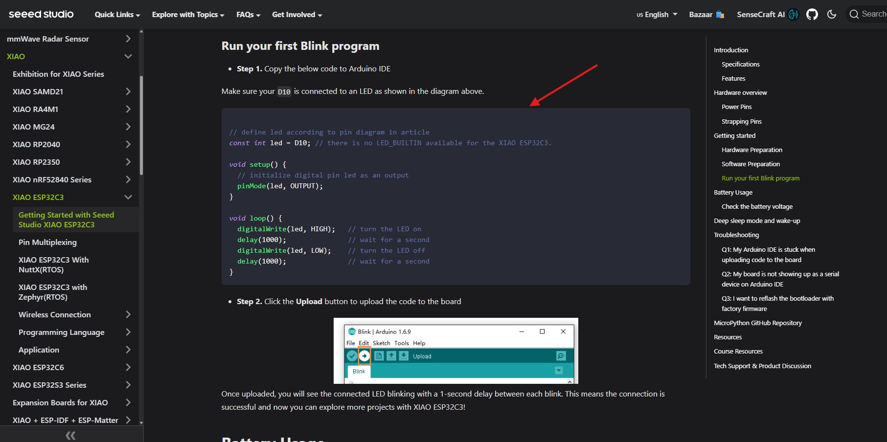
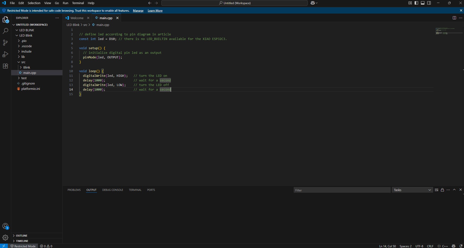
Then paste the code in my source file
Then compile the code for the LED Blink
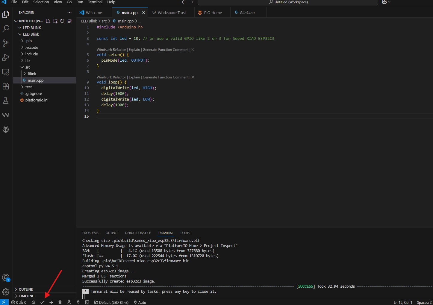
After that we upload our code into microcontroller.