Computer Controlled Cutting
Home ← →
Objective of this Week
- Characterize our lasercutter's focus, power, speed, rate, kerf, joint clearance and types.
- Safety Precaution while using machine
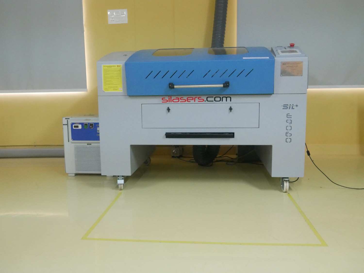
Our Fablab has SIL9060 laser cutting machine
SIL9060
- The SIL9060 is an industrial-grade CO2 laser cutting and engraving machine with a 900 x 600 mm working area. It is designed for precision cutting and engraving on materials like wood, acrylic, leather, paper, and textiles. Equipped with a powerful CO2 laser tube, it delivers high-speed and accurate results. The adjustable laser power allows versatility for different material thicknesses. It features a red dot pointer for precise positioning before engraving. The built-in exhaust system helps remove smoke and debris for cleaner operation. USB and offline control options provide flexibility for users.
- It cost comes around Rs. 3L
Specification:
| | |
| Cutting Material | Acrylic, MDF, Wood, Leather, Paper, etc… |
| Laser Power | 100 Watt |
| Laser Type | CO₂ Sealed Glass Laser Tube |
| Cooling Method | Water Cooling |
| Engraving Speed | 0 - 64,000 mm/min |
| Working Voltage | AC 230V ± 10% |
| Positioning Accuracy | 0.1 mm (Max) |
| Cutting Speed | 0 - 30,000 mm/min |
| Working Area | 600 × 900 mm |
| Operating Temperature | 0°C - 45°C |
| Control Software | Laser CAD |
| Supported File Formats | DXF, AI, PLT, BMP, JPG, PNG, etc. |
Safety Precautions
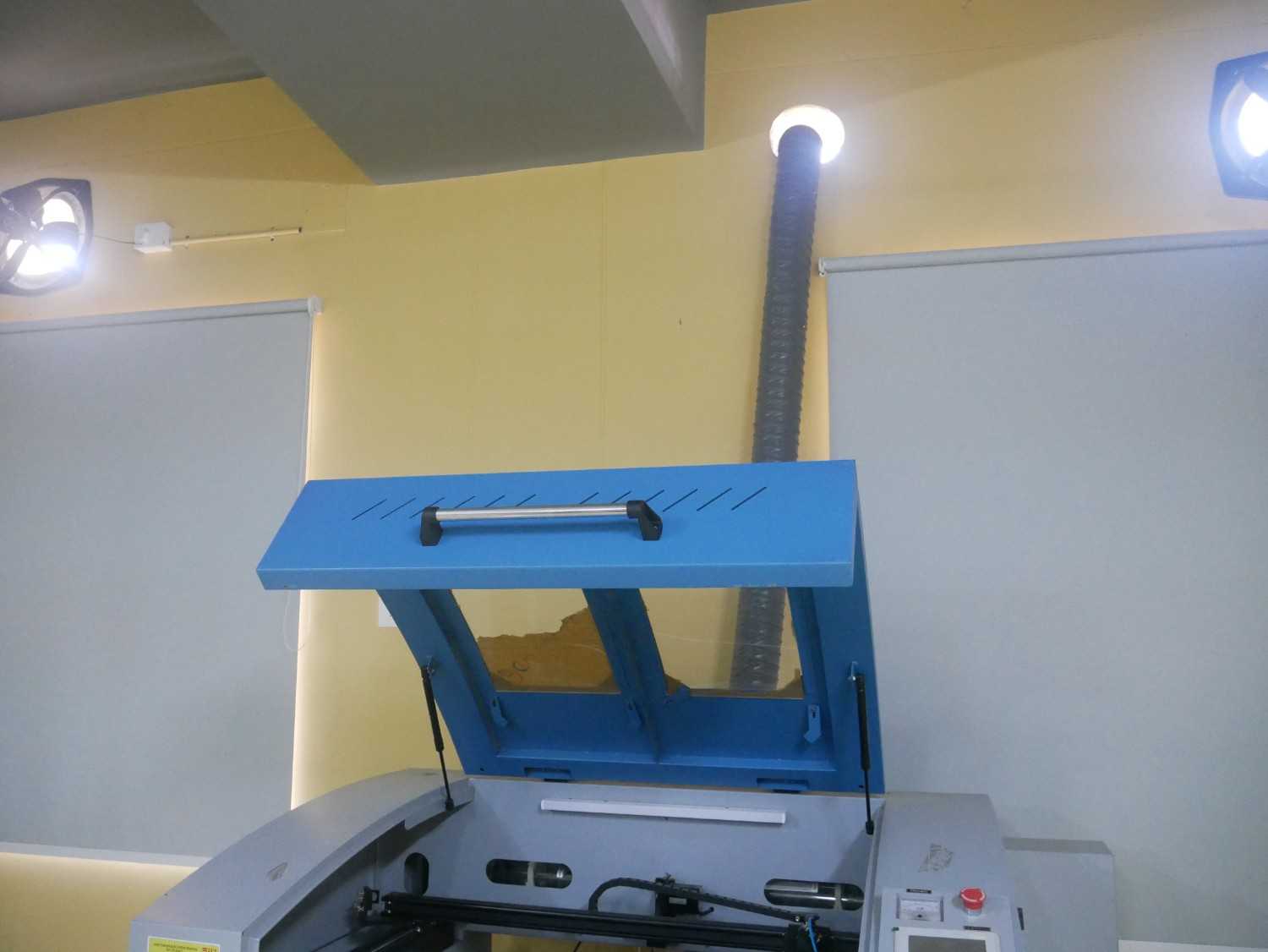
Ventilation
Ensure proper ventilation or use an exhaust system to remove smoke and fumes generated during cutting.
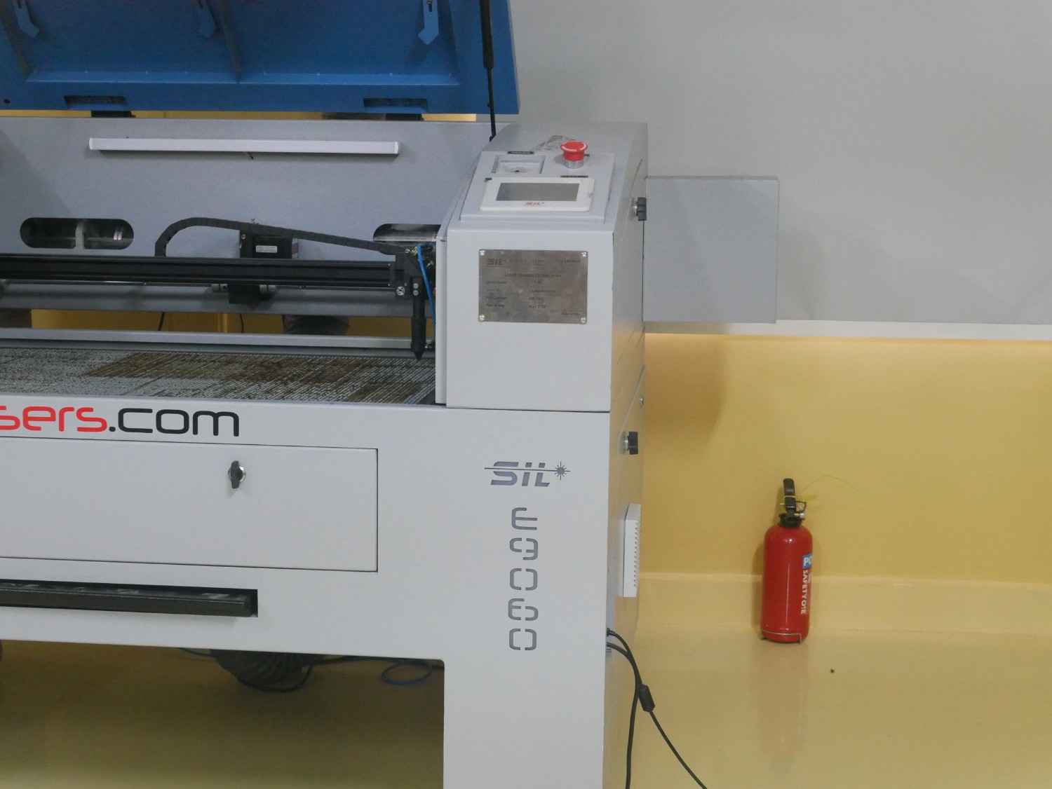
Fire Hazard
Keep a fire extinguisher nearby. Do not leave the machine unattended while operating. Avoid cutting flammable materials.
Material Safety
Check material compatibility before cutting. Acrylic can produce irritating fumes and odors during the laser cutting process, but it is generally considered safe to laser cut when the machine is operated with proper ventilation and an effective exhaust system.
Materials containing chlorine, such as PVC and vinyl, should never be laser cut. These materials release highly toxic gases, including hydrogen chloride, which can be harmful to users and can also damage the laser machine.
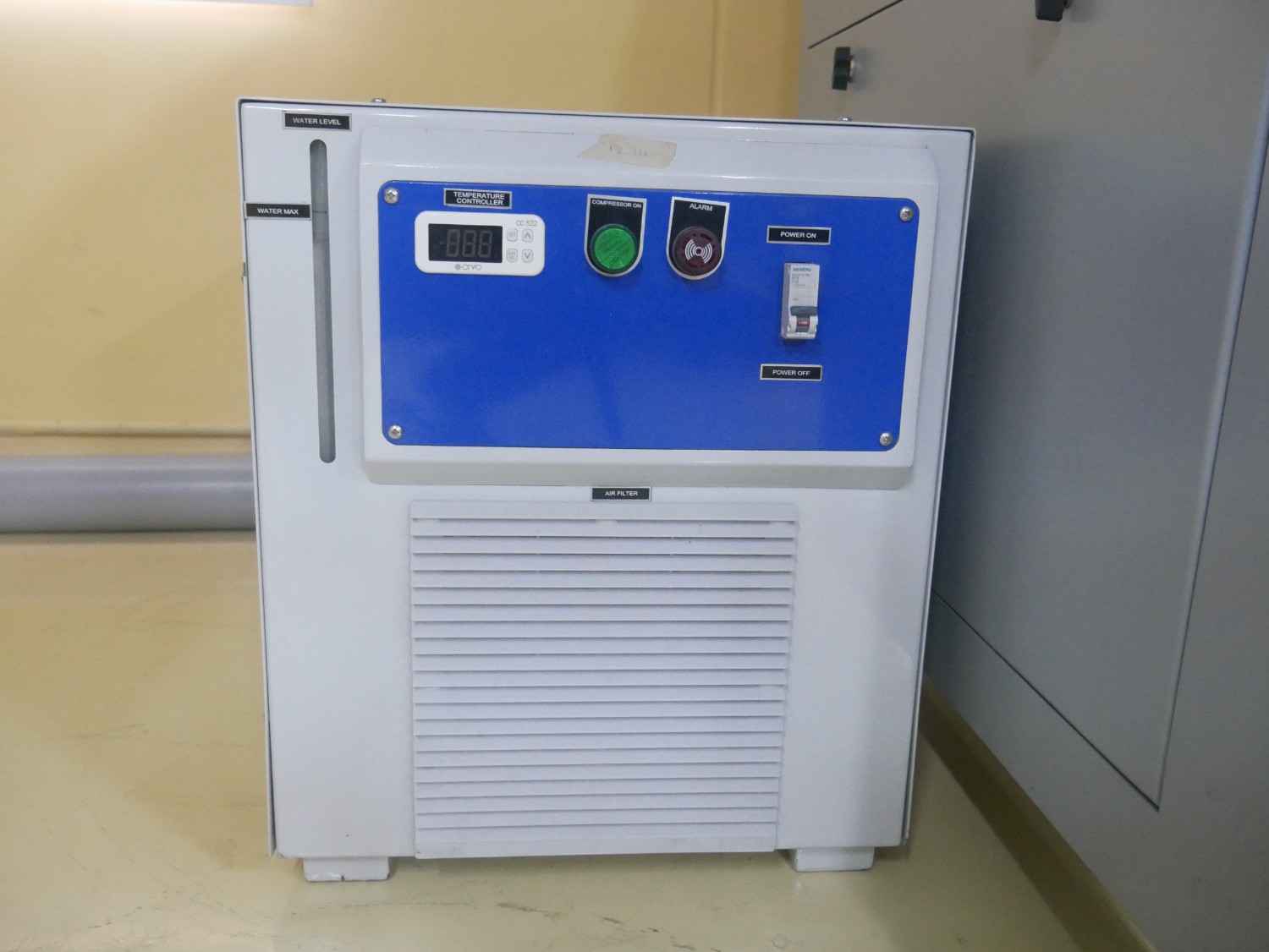
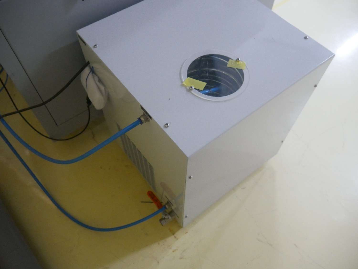
Cooling System
Regularly check the water cooling system to prevent overheating of the laser tube. Use clean, distilled water.
Machine Maintenance
Clean the lens, mirrors, and exhaust system regularly for optimal performance.
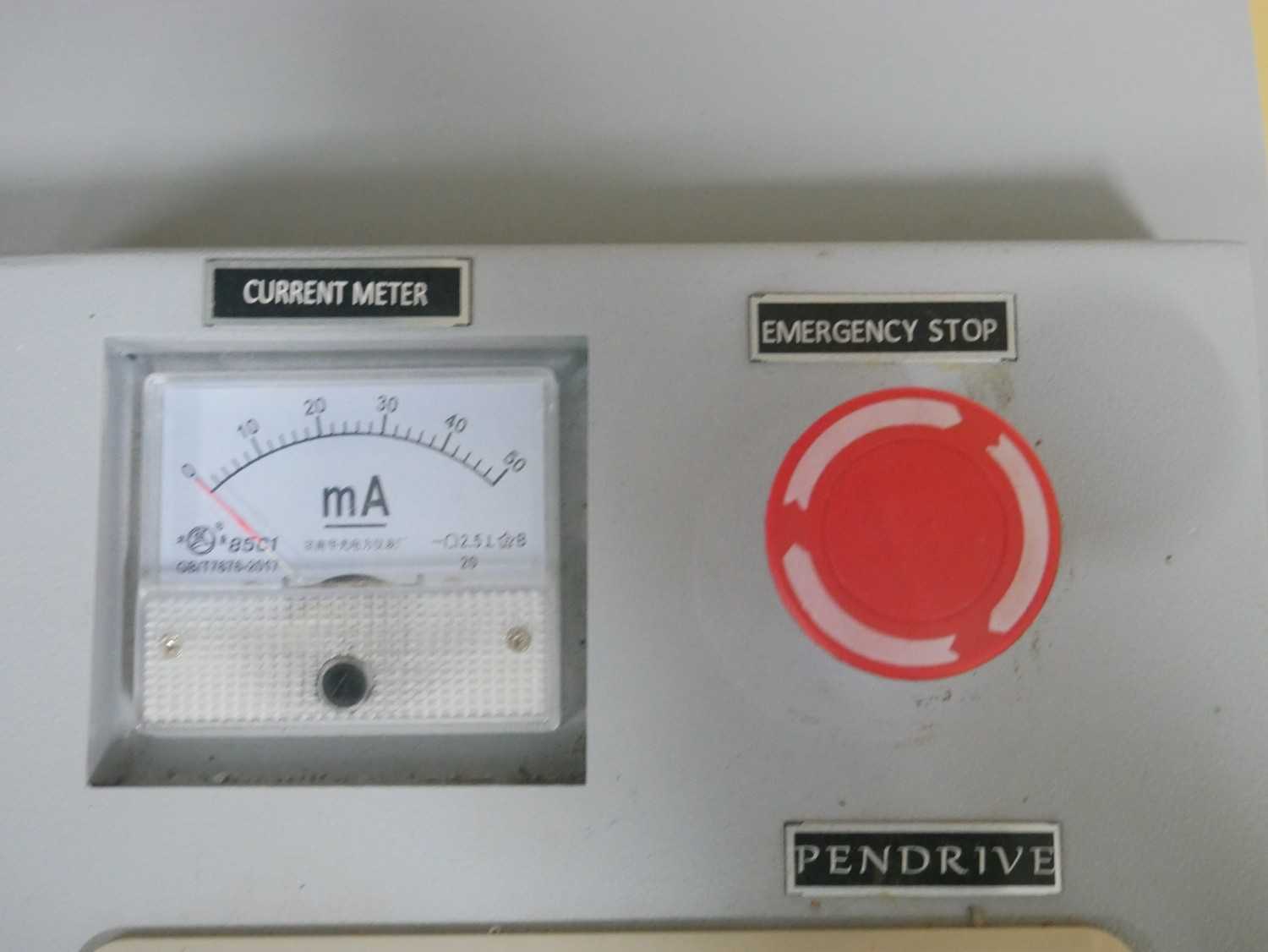
Emergency Stop
Be familiar with the emergency stop button and shut down procedures in case of malfunction.
Laser Test
Kerf
- A kerf test is a method used to measure the material lost due to the cutting process. It determines the kerf width, which is the gap left after cutting
- Material type, thickness, and laser power affect the kerf size.
We take the MDF 2mm sheet and Acrylic 2mm sheet for test the difference between them how the kerf play a major role when cutting.
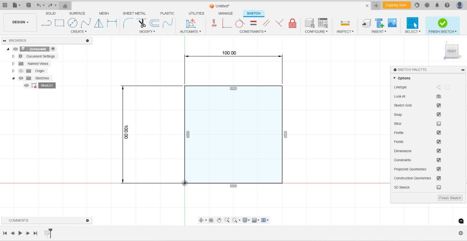
For the 2D design we using the Fusion 360,
Fusion 360
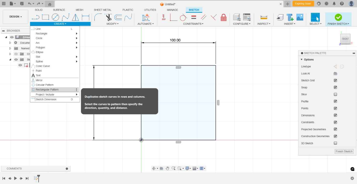
At First we draw the rectangle and set the dimension 100*100 mm, then add the inner lines by making it divided into 10 parts of rectangle.
Then take out the DXF file from Fusion
For the cutting process software we use the LaserCAD.
LaserCAD
We import the DXF file into the LaserCAD software and set the power and speed for cutting out completely.
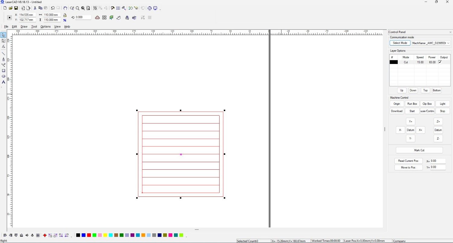
Download it in the Laser machine .
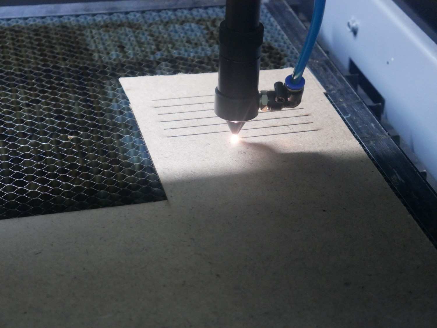
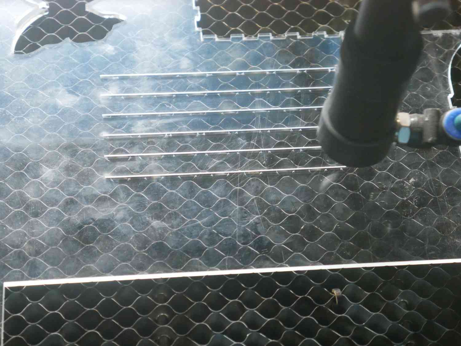
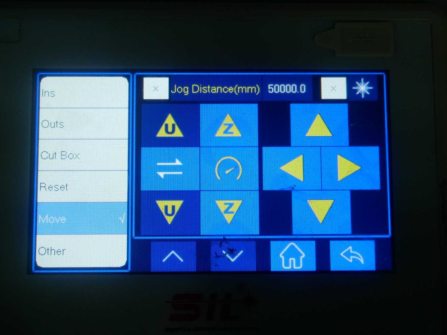
Cutting Process
Set the origin of the nozzle where we required to cut
Check out the box mode whether our space is enough to cut the piece
Finally start the laser machine and ensure the laser and exhaust is ON.
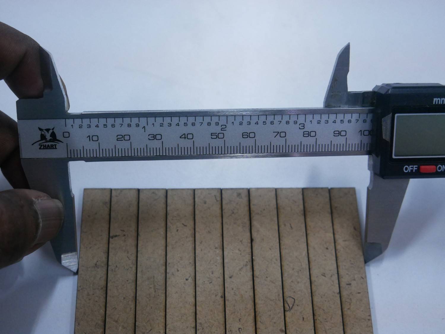
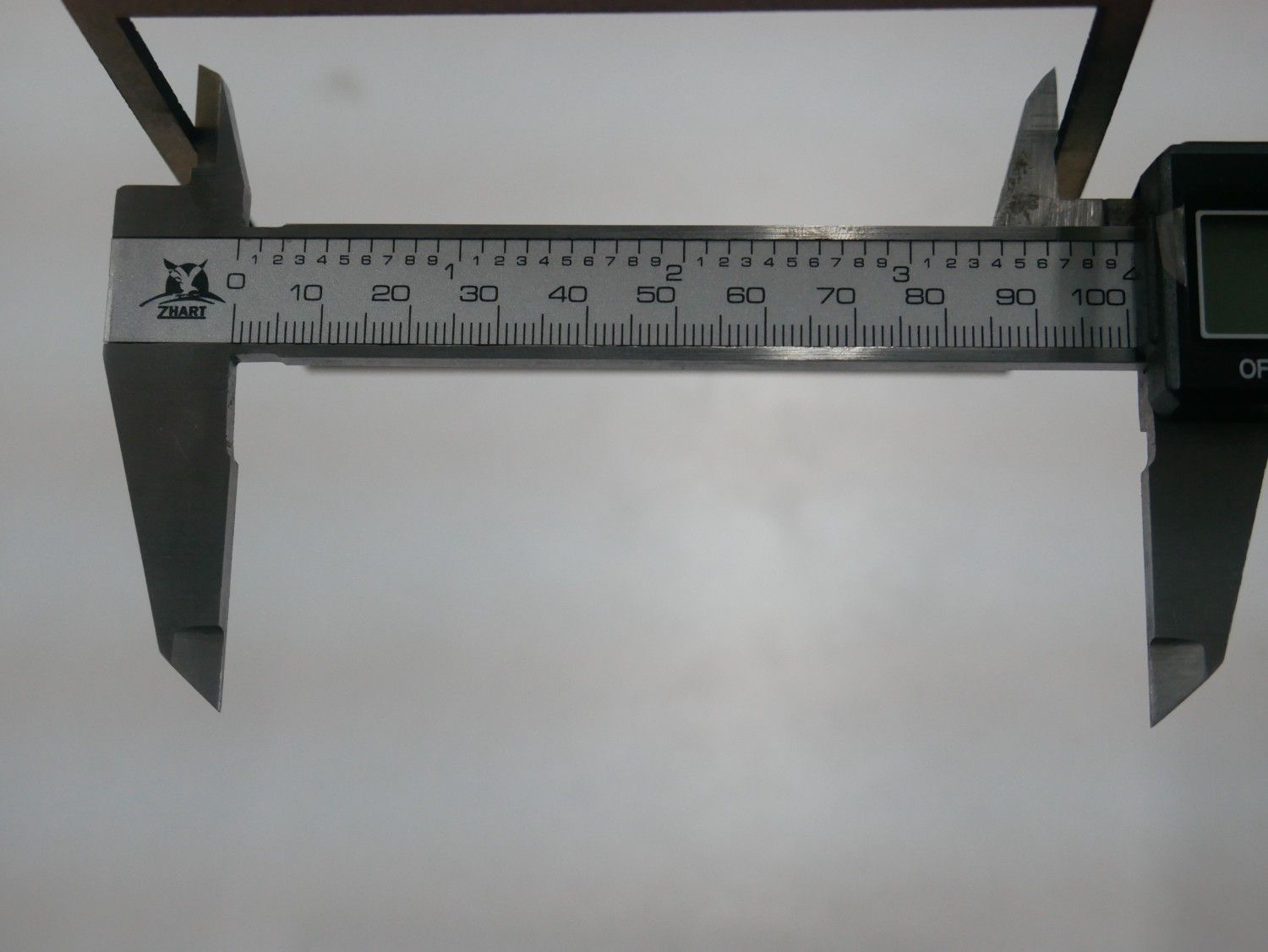
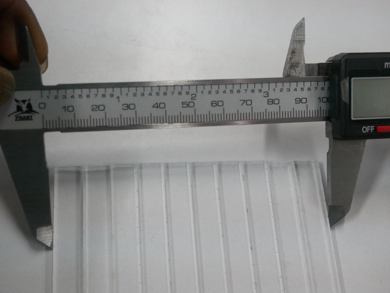
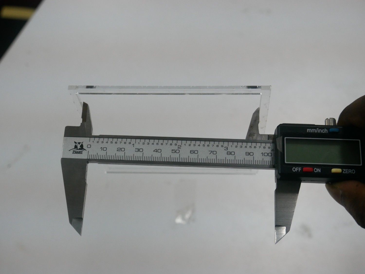
Calibration
Take out the cutted piece from the laser machine and check the dimension inner of the rectangle and 10 cutted piece rectangle outer edge by using vernier caliper.
Test Result
| Material | Kerf |
| 2 mm MDF Board | 10 piece outer check - 0000 |
| 2 mm MDF Board | Sq inner check - 0000 |
| 2.5 mm Acrylic sheet | 10 piece outer check - 0000 |
| 2.5 mm Acrylic sheet | Sq inner check - 0000 |
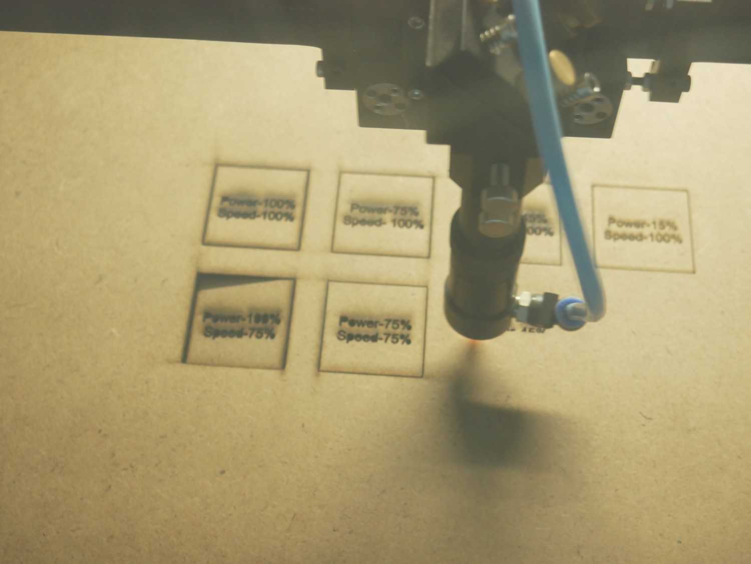
Power VS Speed
We tested the power and speed how it impact when changes it relative to each other.
We conducted the test by using two different material which is 2 mm MDF board and 2 mm Acrylic sheet.
For the 2D design we using the Fusion 360
Fusion 360
Create the new sketch and draw one rectangle and set the dimension
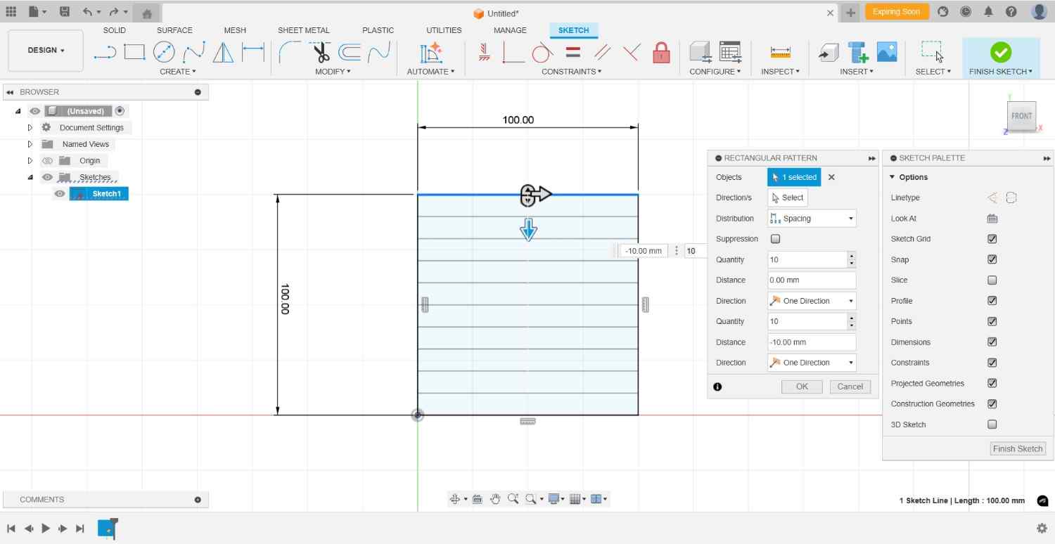
By using the Rectangular pattern option created the 4 rows and 4 columns
By using the Text option write the Power VS Speed letters and change the percentage according to each others
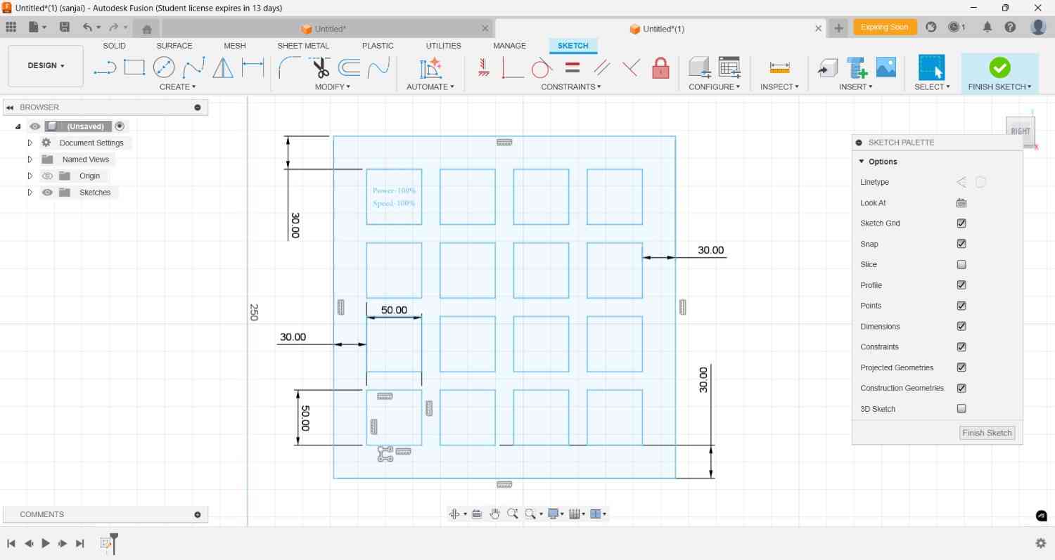
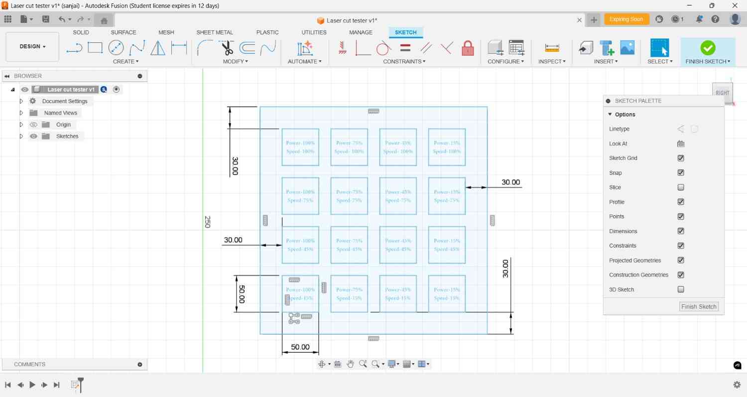
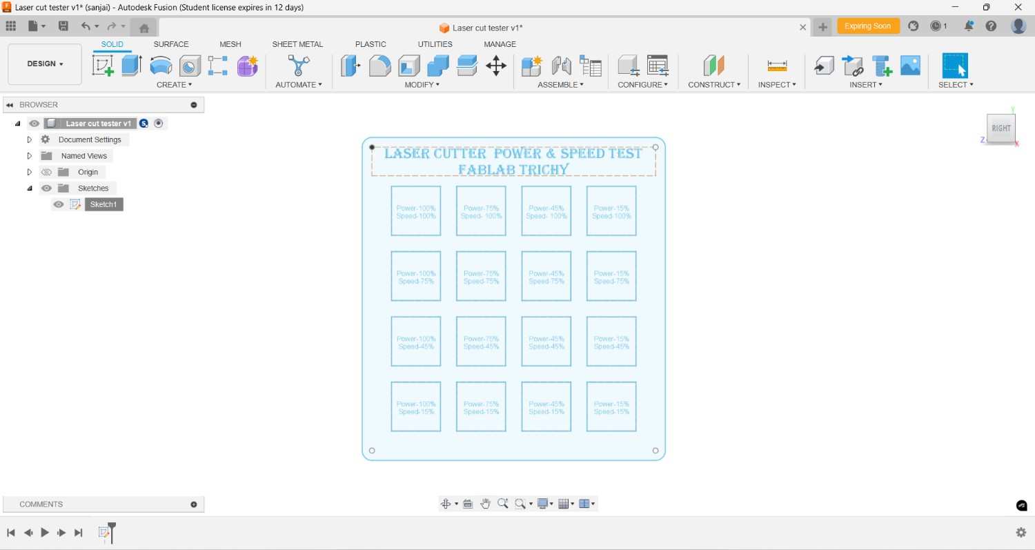
Then took out it into the DXF format.
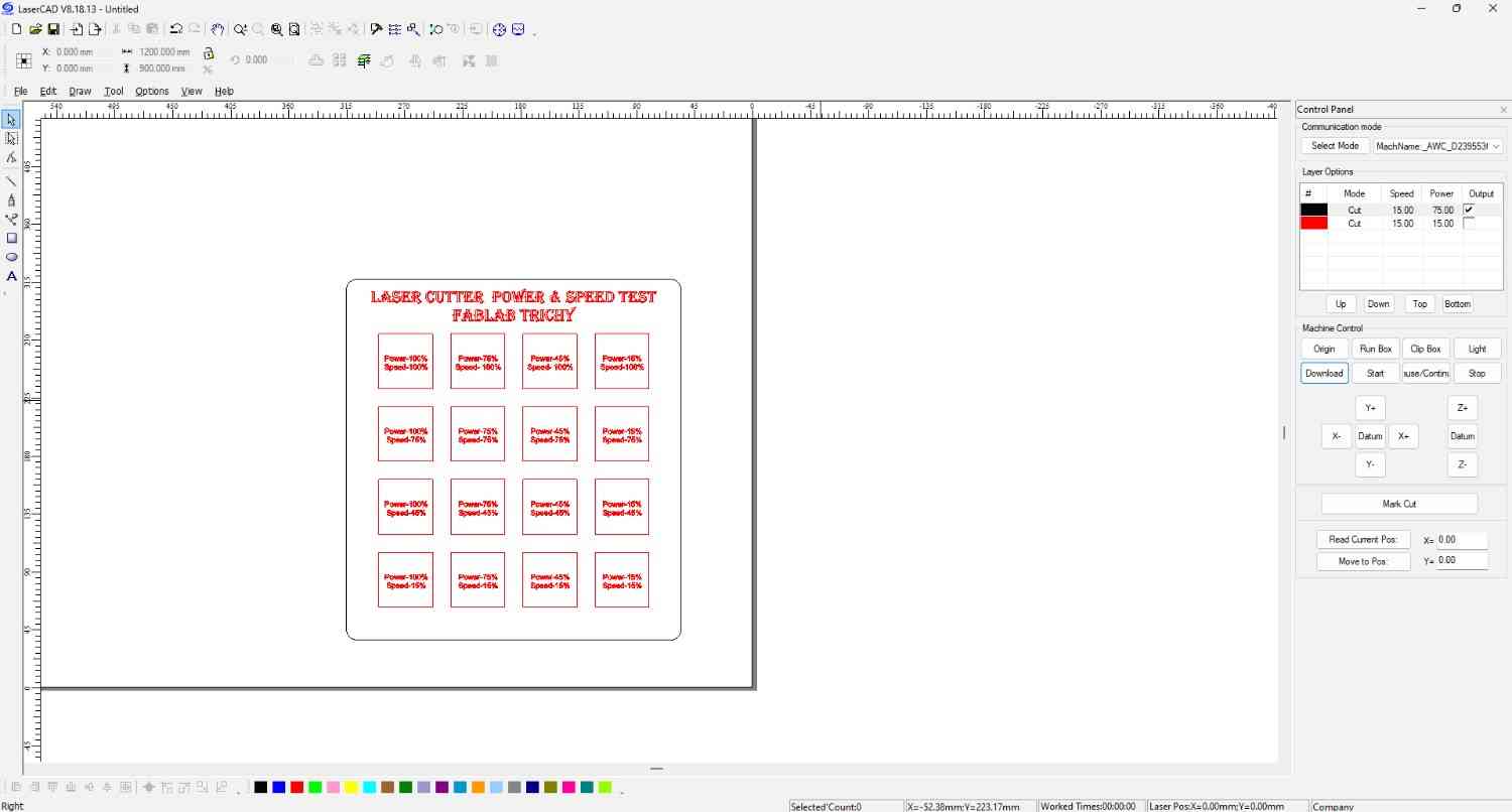
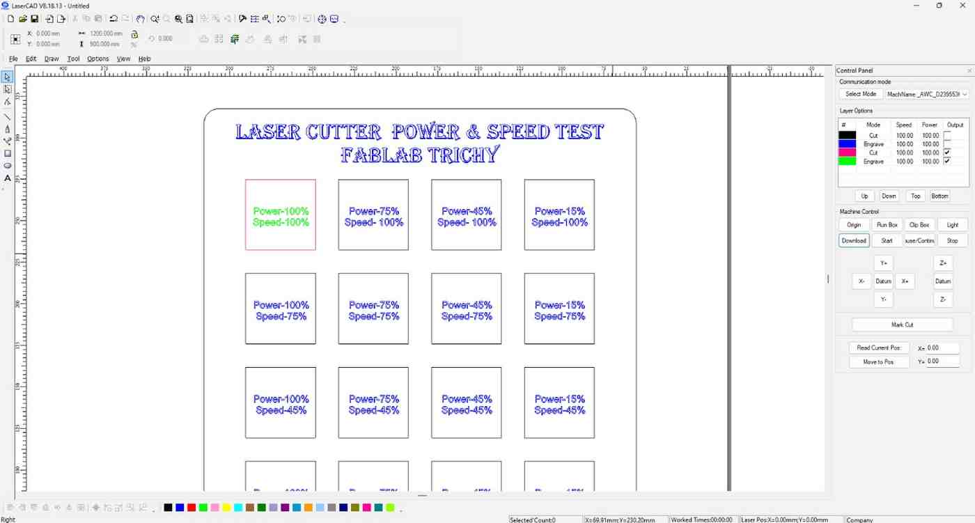
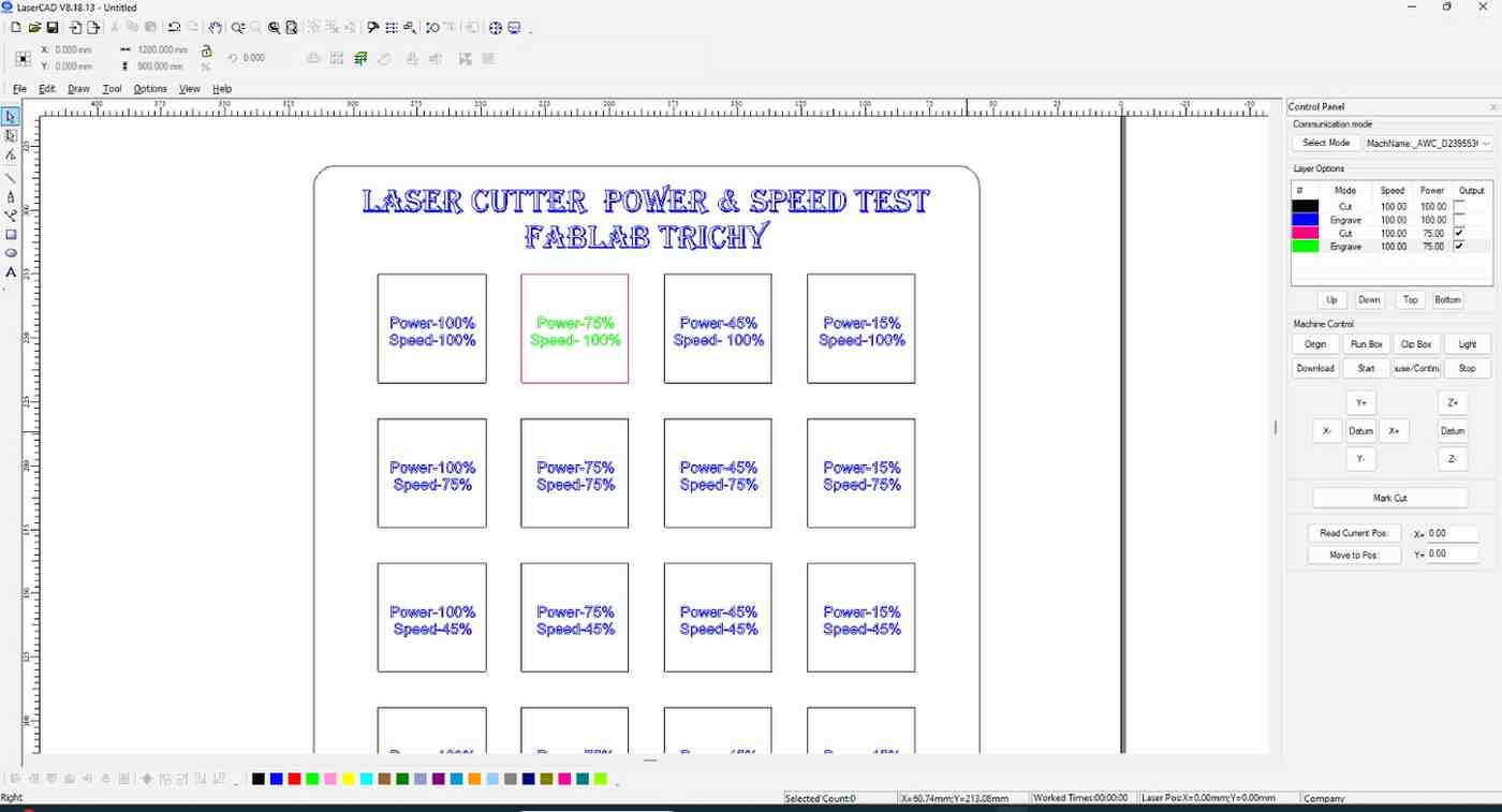
LaserCAD
We import the DXF file into the LaserCAD software
We use the different colours to navigate which one is cutting, engraving and remains should not change
For the rectangle box we did the cutting process and engraved the letters regarding what it is mentioned in that place.
Cutting Process
Set the origin of the nozzle where we required to cut
Check out the box mode whether our space is enough to cut the workpiece
Close the door for safety precaustions and properly suck out the burned gas by exhaust
Finally start the laser machine and ensure the laser and exhaust is ON.
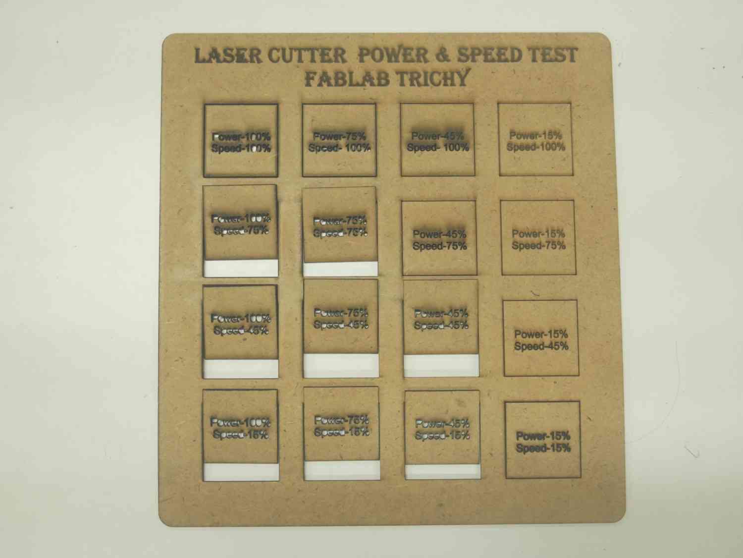
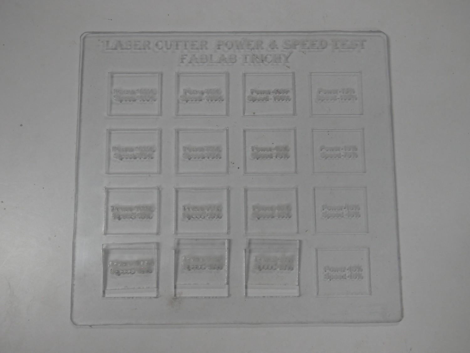
Test Result
MDF and Acrylic has obviously seen as differnt performace when it done in cutting and engraving
This is really helpful to the new person who is going to cut or engrave these different material by using it as reference.
Challenges
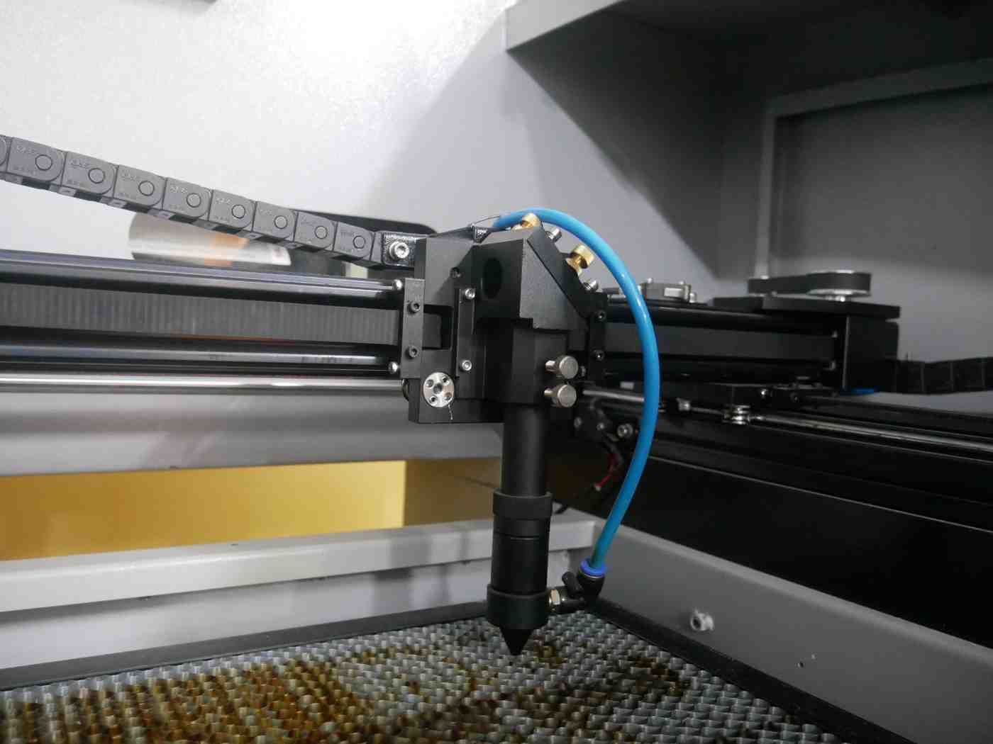
For the best Focus of the laser cut is 8 mm clearance from nozzle tip to laser bed.
In our machine Auto leveling in Z path option is not enablilng so we try to adjust manualy.
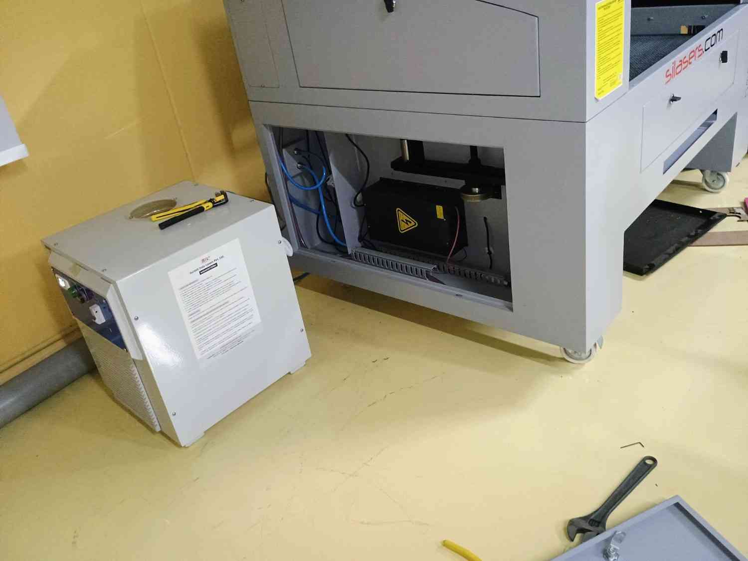
At that time we ended with one issue, for the Z path movement in laser machine the bed only moving up and down with the help of two servo motor which is attached below the machine.
The laser machine bed is struck in bottom when we give the resetting option and show the message Trigger limit.
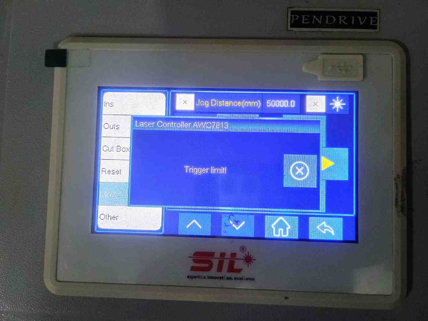
The limit switch in the right side of the machine is not woriking properly so the bed is one sidely go little bit beyond the limit.
So the bed is struck and make a noise vigorously, then we start to remove the covered sheets both side of the machine and check it first which side is causing that problem and we diagonsed the right side.
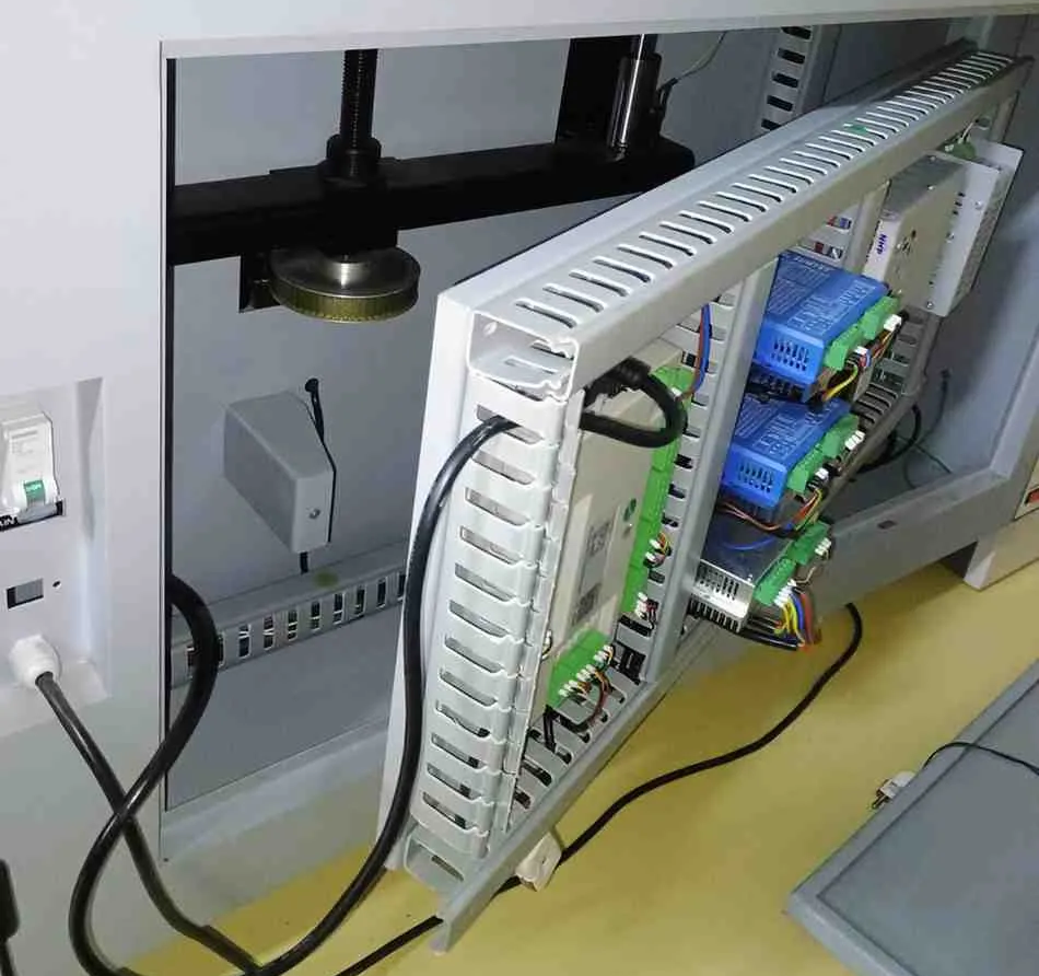
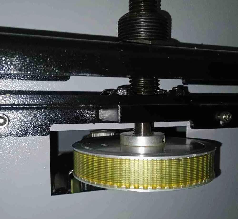
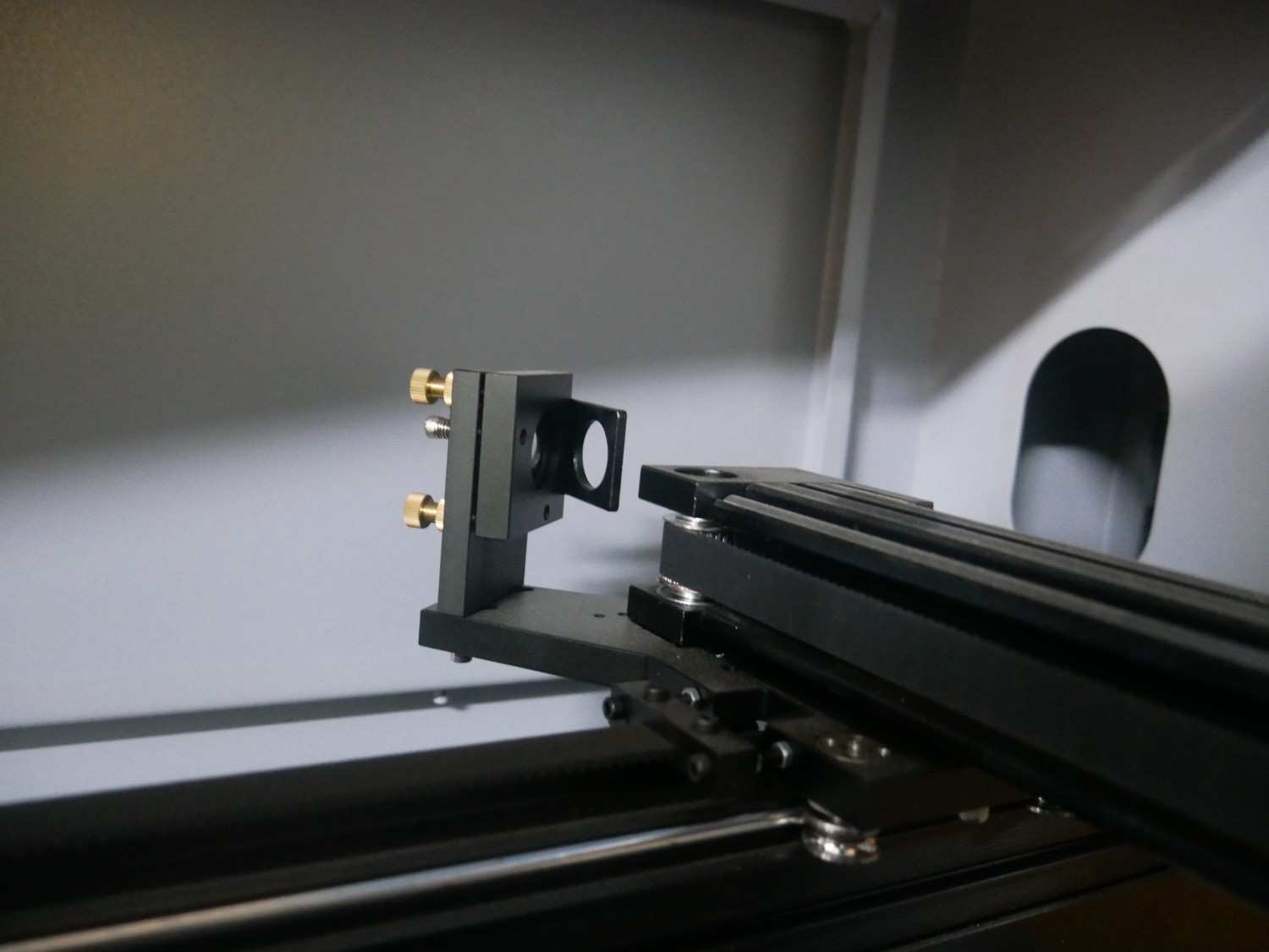
Then we use the tightening tool to loose the rotary part which is attached with the Servo motor.
By forcing the rotary part we straight it and rotate it manualy to get it above in the limit switch without touching it little bit.
Then we change the limit switch and check both sides rotary part to align it in same level by using the vernier caliper.
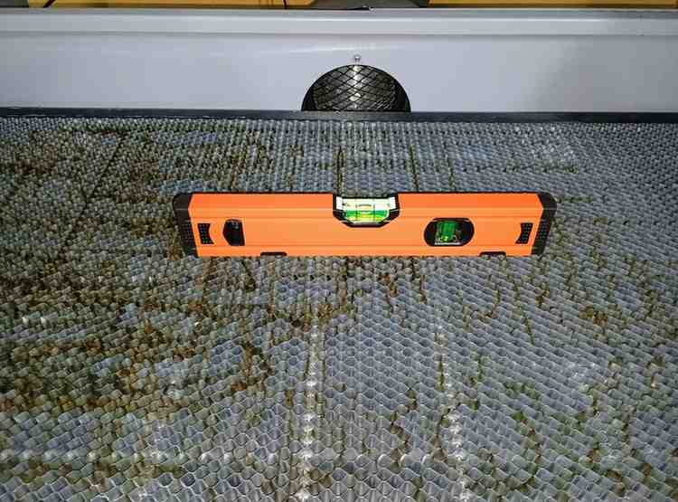
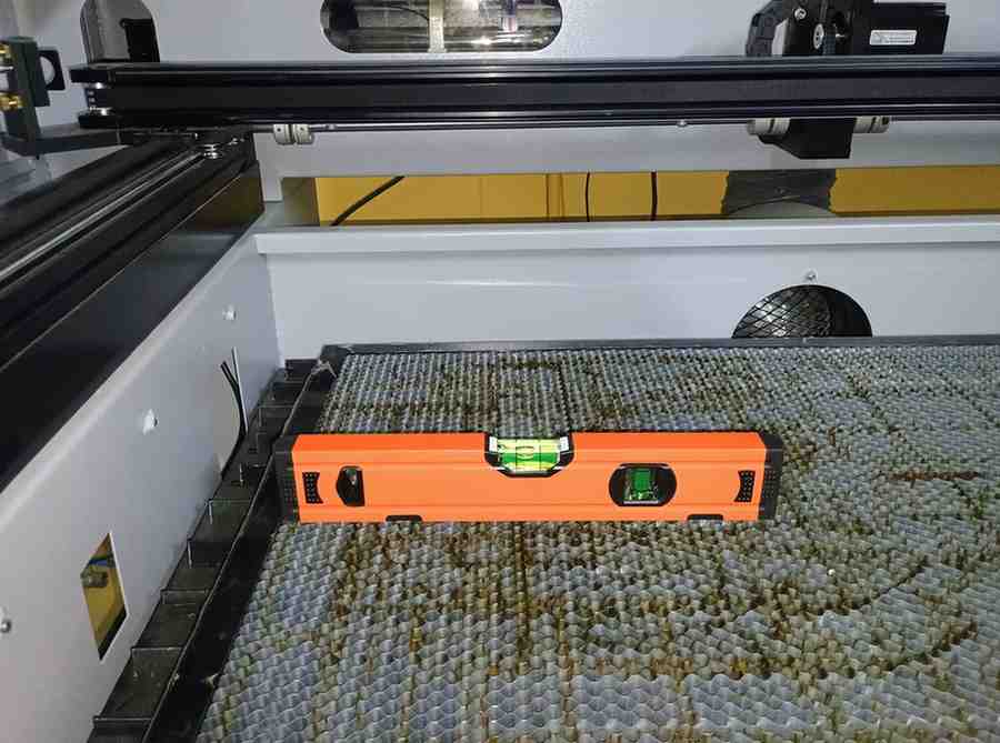
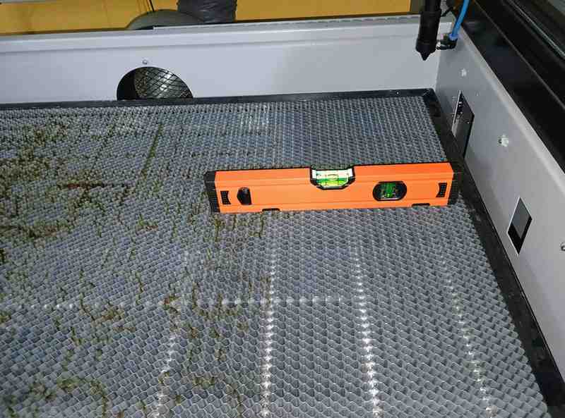
At first we have 14 mm difference between each other and we rotate it manualy. After aligning it we also check it out by using the Spirit level to ensure that 3 positions has the same level.
Then adjusting the bed height for the Nozzle tip distance between them in 8 mm to cut the materails proprely.
After spending 2 hours we fix this problem and run it properly.
Reference Files
- Kerf test - DXF File
- Power VS Speed test - DXF File