Electronic Design
Home ← →
Objective of this Week
- To use the test equipment in our lab to observe the operation of a microcontroller circuit board
- Demonstrate the use of a multimeter and oscilloscope
Oscilloscope
Oscilloscope is an electronic test instrument used to observe and analyze varying signal voltages.It displays a graph of an electrical signal, usually as voltage (Y-axis) over time (X-axis).
- Receiving a signal through a probe connected to a test point in a circuit.
- Amplifying and conditioning the input signal to suitable levels.
- Sampling the signal using an analog-to-digital converter (in digital scopes).
- Displaying the waveform on a screen as voltage vs. time.
- Allowing user adjustments for time base, voltage scale, and triggering.
- Analyzing waveform features such as rise time, frequency, or distortion.
- Storing data for further analysis or exporting in modern digital models.
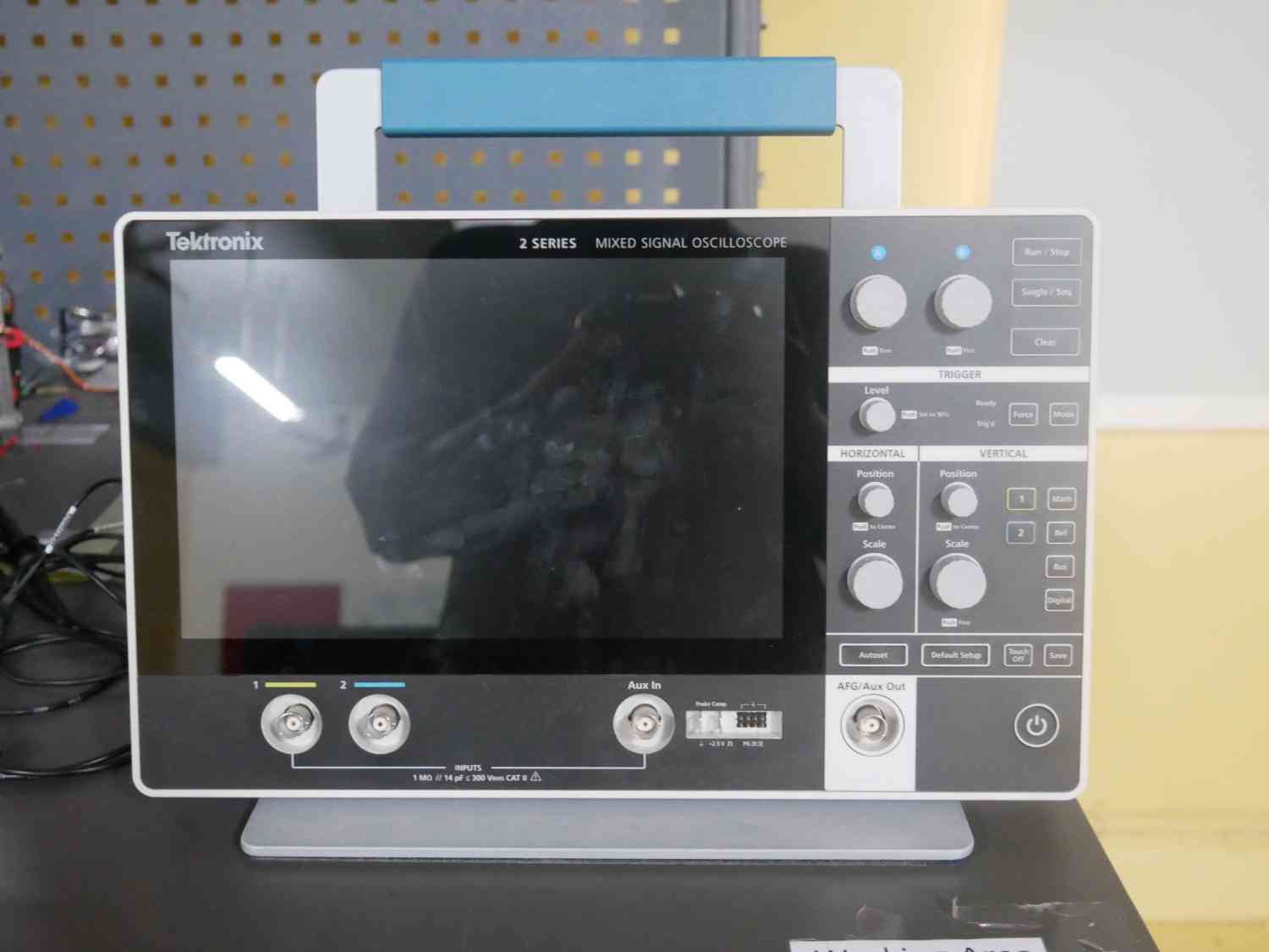
In our lab we have the Tektronix - MSO-22
Specification
| Feature | Specification |
| Model | Tektronix MSO22 |
| Analog Channels | 2 |
| Bandwidth Options | 70 MHz / 100 MHz / 200 MHz / 350 MHz / 500 MHz (upgradable via license) |
| Sample Rate | Up to 2.5 GS/s (half channels), 1.25 GS/s (all channels) |
| Record Length | 10 million points per channel |
| Vertical Resolution | 8 bits (up to 16 bits in High-Resolution mode) |
| Digital Channels (Optional) | 16 channels (MSO capability) |
| Waveform Capture Rate | >4,000,000 wfms/sec |
| Display | 10.1” capacitive touchscreen, 1280 x 800 resolution |
| Connectivity | USB 2.0, LAN (Ethernet), VNC remote access |
| Trigger Types | Edge, Pulse Width, Runt, Timeout, Logic, Setup & Hold, Rise/Fall Time, Bus |
| Math & Analysis Tools | 37 measurements, cursors, FFT, limit testing, equation editor |
| Optional Features | 50 MHz AFG, 4-bit pattern generator, protocol decode (I2C, SPI, UART, CAN, LIN) |
| Form Factor | Portable, approx. 1.5 inches thick |
| Power Option | External power supply; optional battery pack |
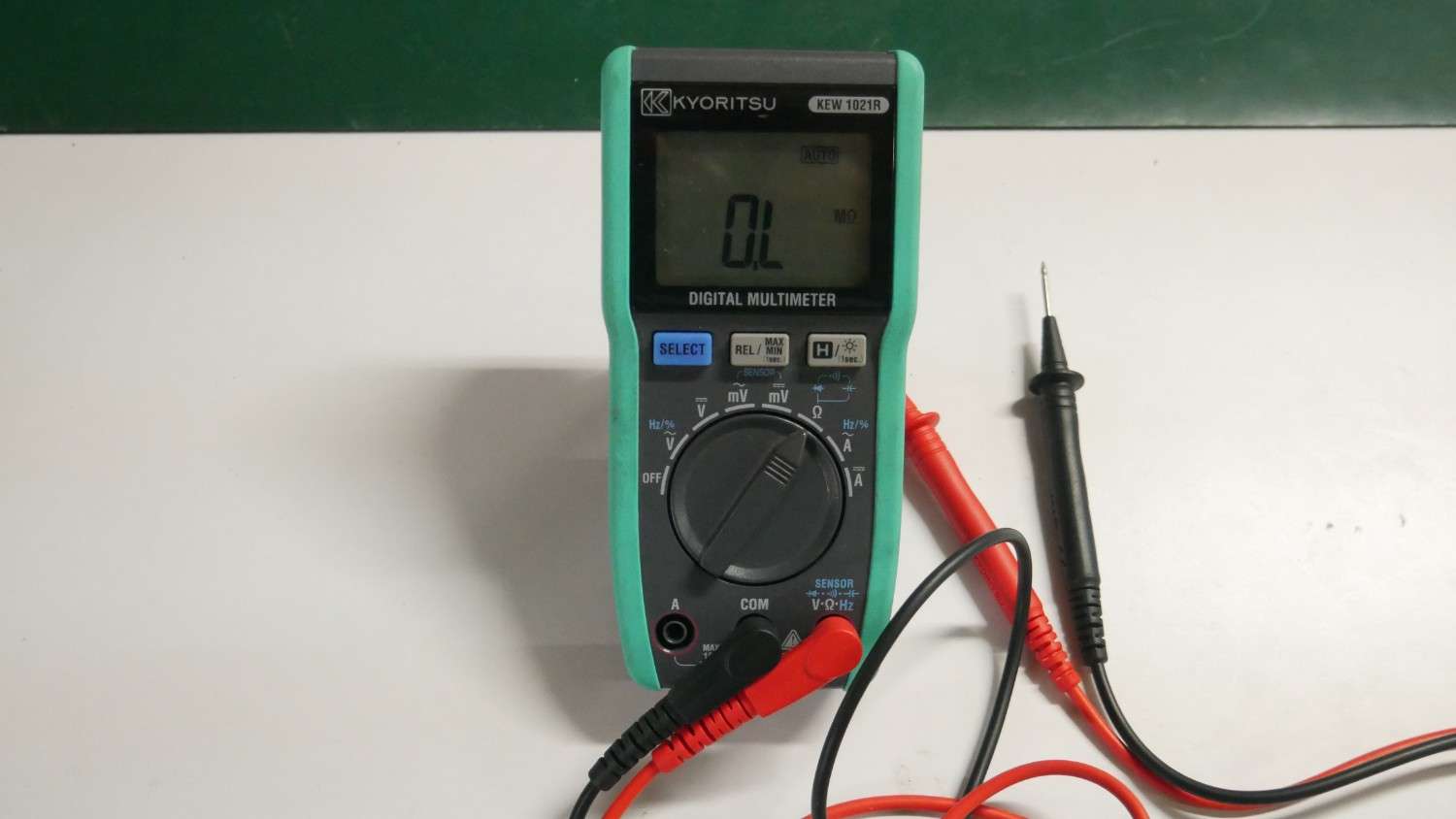
Multimeter
Multimeters are essential for diagnosing electrical/electronic issues in circuits. It is a versatile electronic measuring instrument used to check basic electrical parameters like Voltemeter, Ammeter, Continuity test, etc…
- Measuring the Voltage and Current both AC and DC
- Measuring the resistance value
- Troubleshooting the electronic components
- Checking the continuity test on circuit
Testing
We tested our Multimeter and Oscilloscope by using the LED Blink code, connect the LED with GPIO pin and update the code in microcontroller
For Multimeter we can see the voltage variation whenever the LED is blinking but still the value not get proper
For the Oscilloscope we connect the prope and make a test of the same LED blink, the visualize form of the signal show very clear after we adjusting the Vertical and Horizantal switchs.
Conclusion
Learning outcomes
- Know the advantages of both Multimeter and Oscilloscope
- Figure out how to troblue shoot the electronic components by using Multimeter
- By the help of Oscilloscope we can analyze the sensors signal functions
- In Oscilloscope we can see the voltage versus time action of our both input and output devices.