CNC + Mods
Summary
After understanding the Roland SRM-20 CNC machine, I moved on to the PCB manufacturing process using MODS. I followed a past Fab Academy tutorial (FaceLabel) to generate the correct milling file. After milling the PCB, I checked for short circuits before proceeding with manual soldering. However, I encountered an issue where the resistors were too small for easy soldering, leading me to consult the instructor, who advised me to update my design with larger components for easier assembly.
Work Process Detail
1. Preparing for PCB Milling Using MODS
- I followed the FaceLabel tutorial, a past Fab Academy student project, to understand the process.
https://fabacademy.org/2024/labs/techworks/students/faisal-abuhayyeh/week4.html
Check Ghadeer and i group assignment page in order to know how we configured MODS:
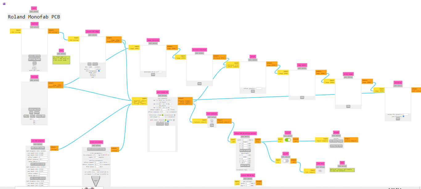
- I uploaded my PCB design to MODS, ensuring that I selected the correct settings for milling.
- After processing, I exported the file in the correct format for the CNC machine.
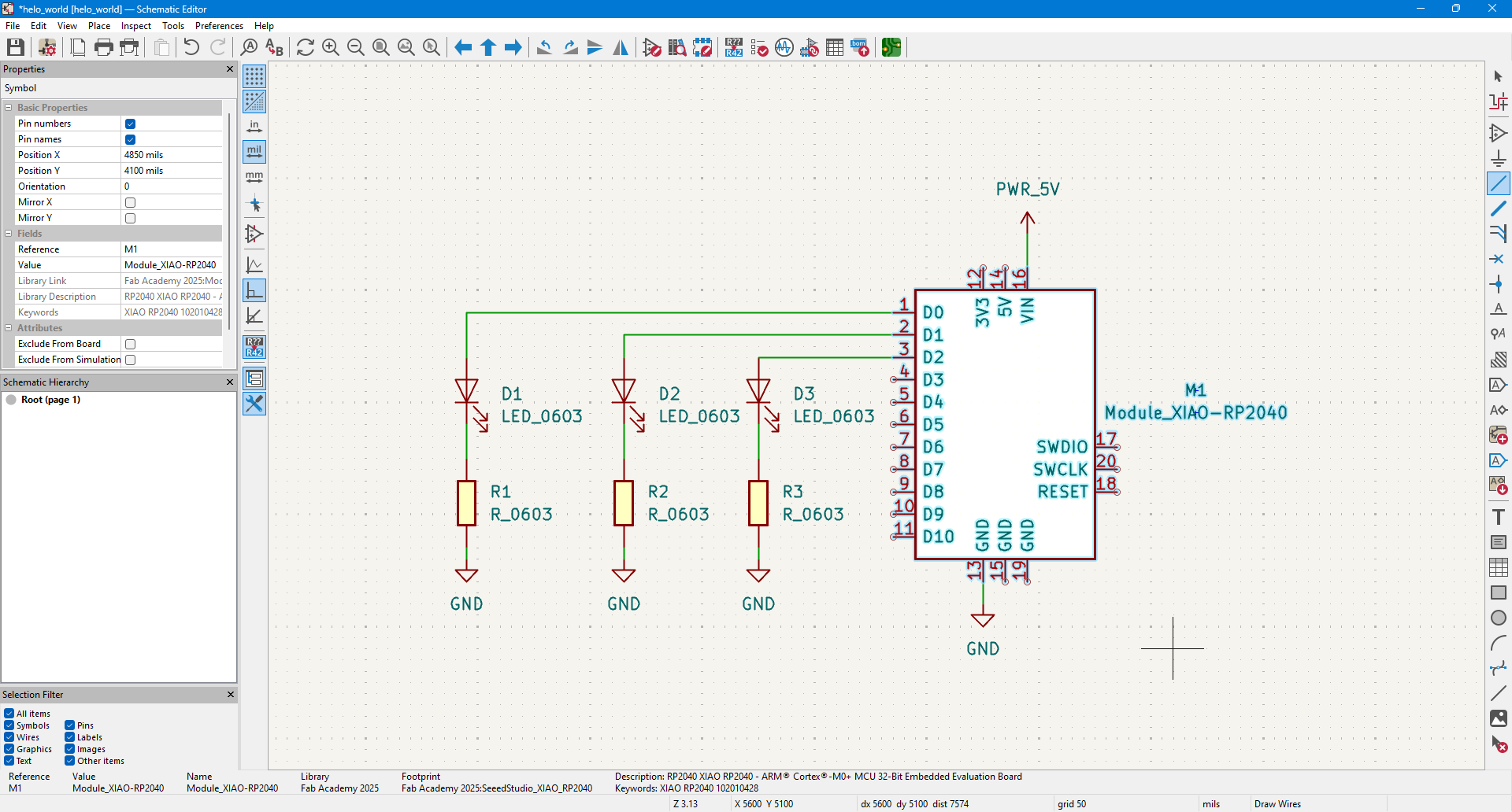
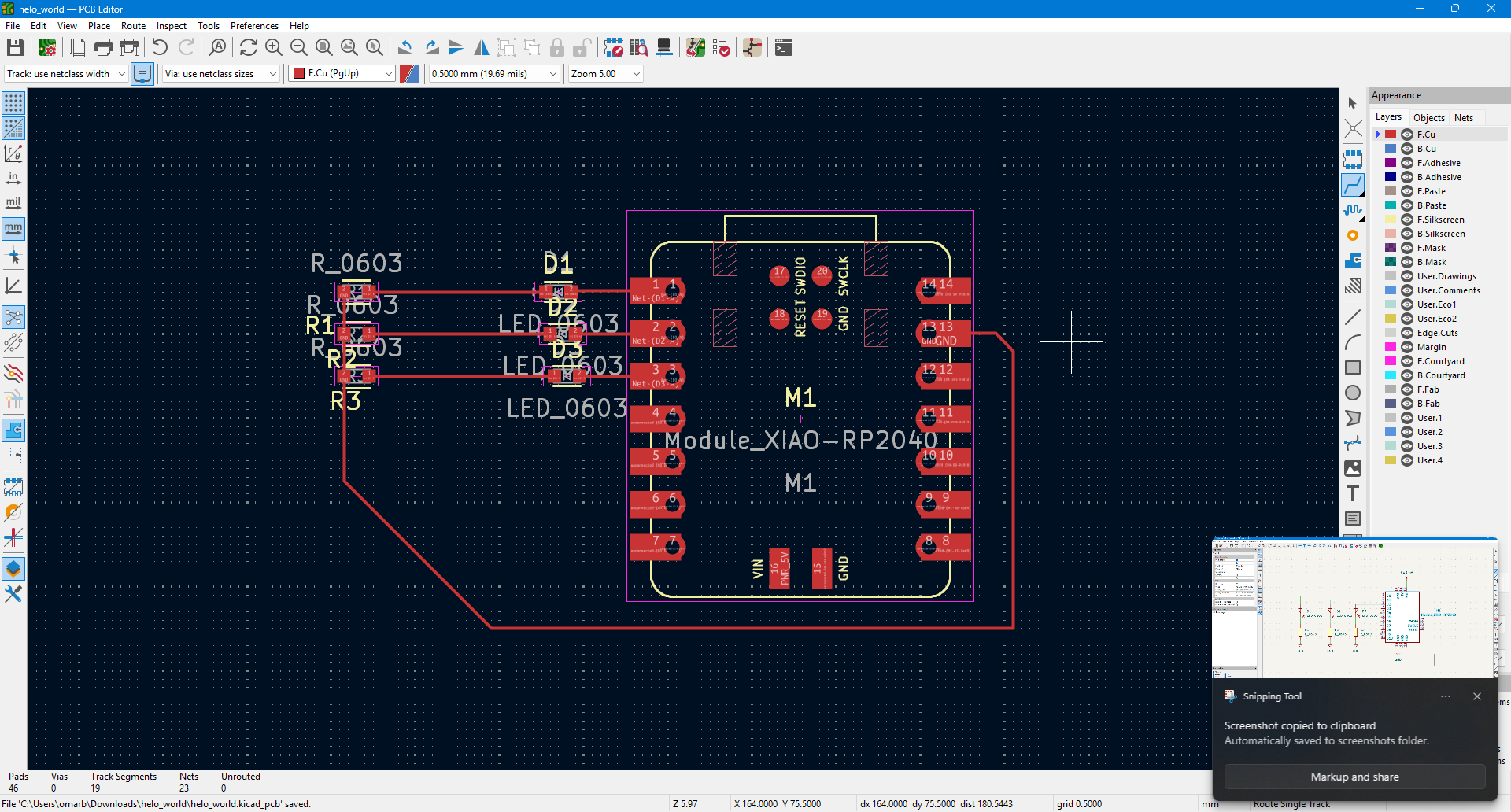
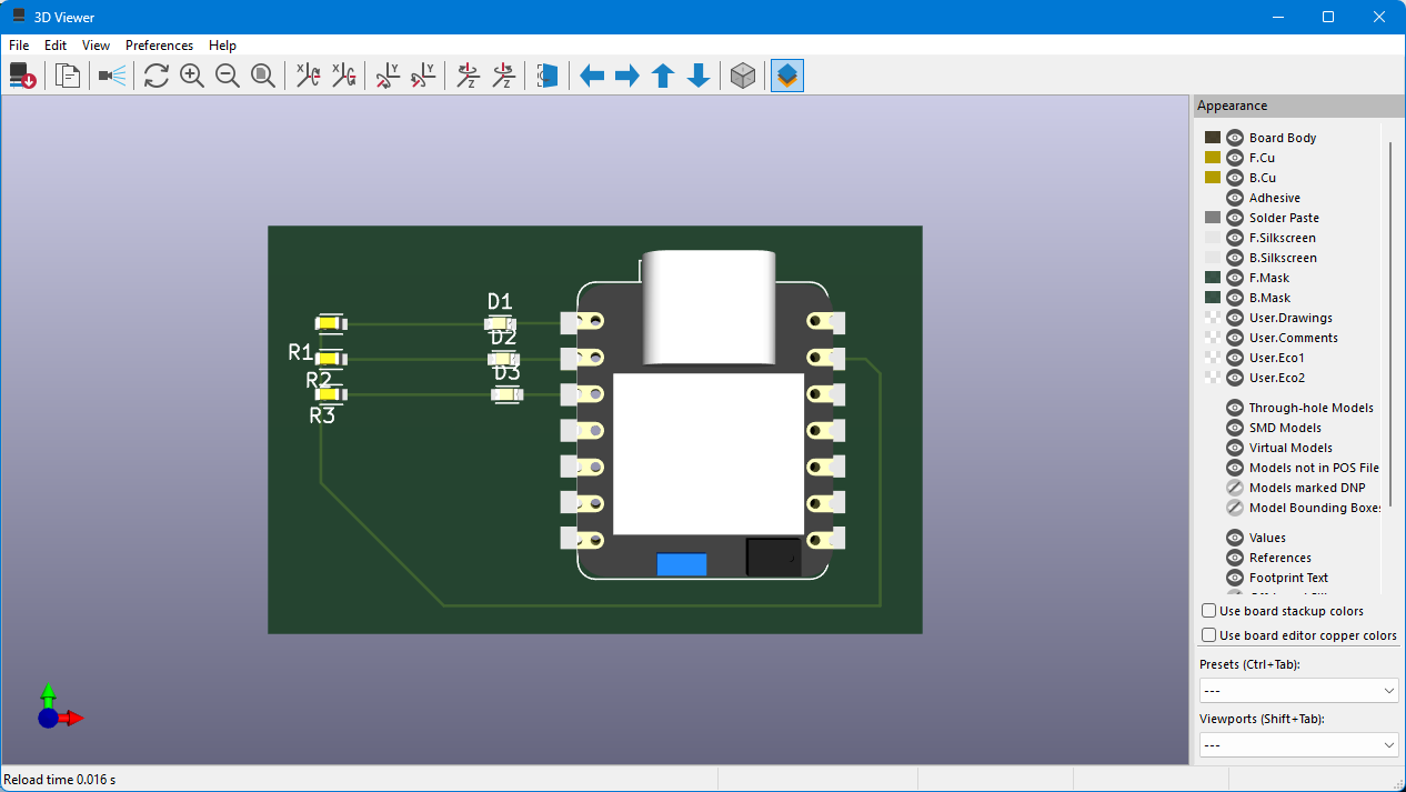
2. Mounting the End Mill and Starting the Milling Process
- I installed the correct end mill for fine PCB engraving.
- I secured the copper-clad board onto the machine bed.
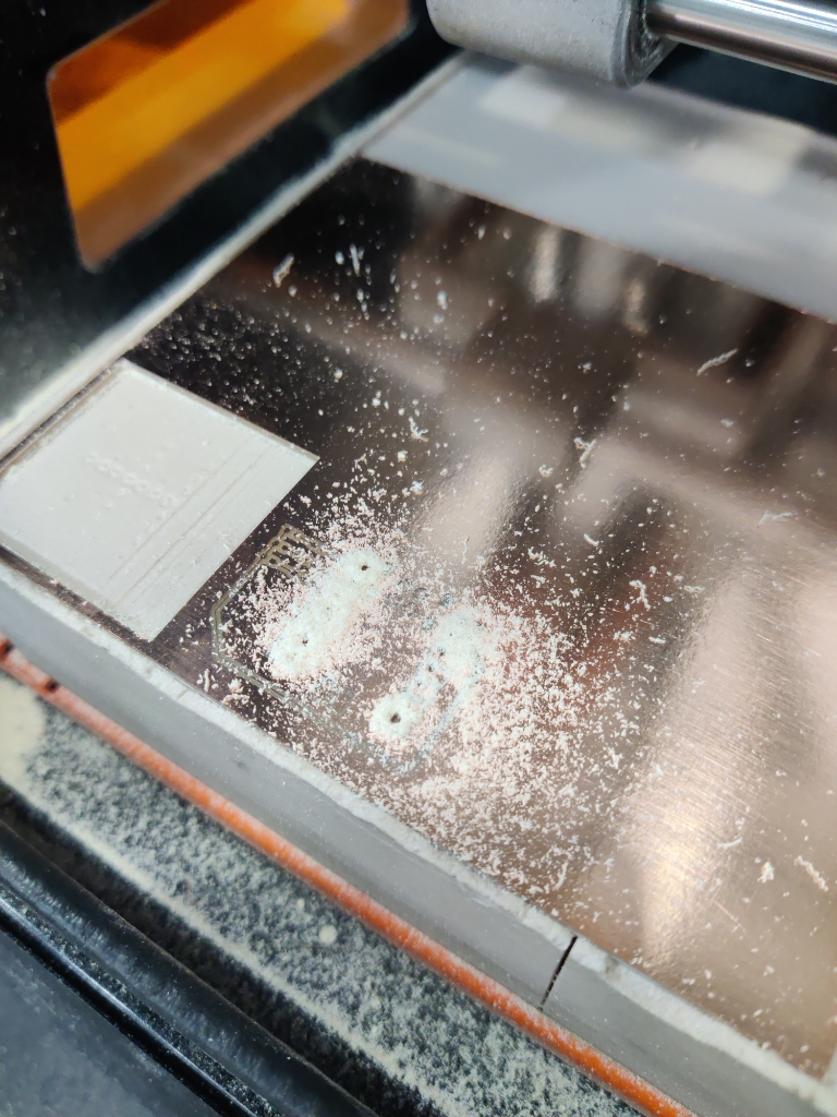
- I initiated the milling process, ensuring precise cutting.
📷 In this photo: The PCB being milled by the Roland SRM-20.
3. Inspecting the Milled PCB for Short Circuits
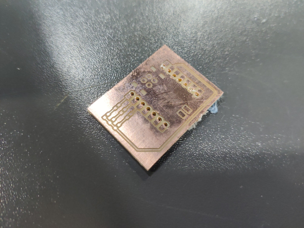
- After milling, I cleaned the PCB to remove excess copper dust.
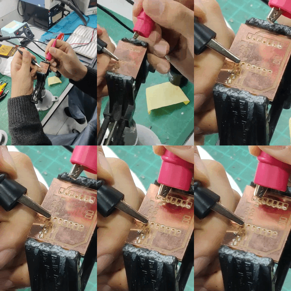
- I used a multimeter to check for short circuits, verifying that no unwanted connections were made.
- The results were good, and the traces were properly cut.
📷 In this photo: The milled PCB with fine traces visible.
4. Soldering the PCB Components (Problem)
- I began the manual soldering process, adding resistors, capacitors, and connectors.
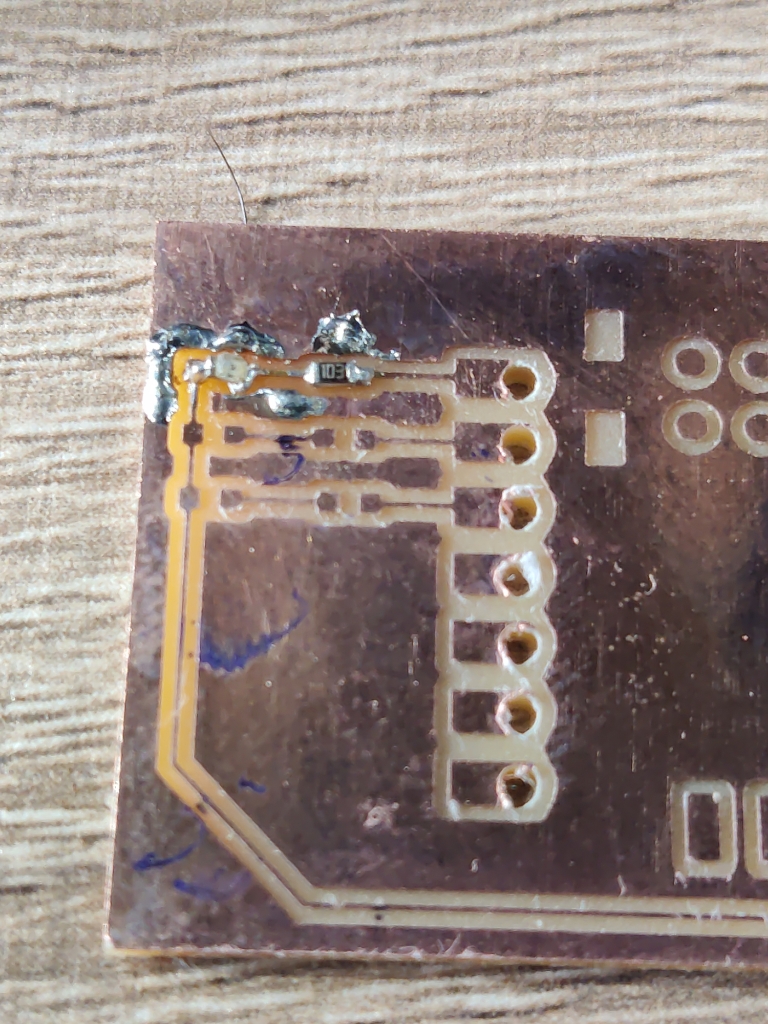
- However, I realized that the resistors were too small, making manual soldering difficult.
📷 In this photo: The soldering process, showing the tiny resistor placement issue.
5. Consulting the Instructor & Updating the Design
- After struggling with soldering, I asked the local instructor for advice.
- He recommended updating my design to use larger components for easier manual soldering.
- I noted the changes needed and planned to modify my PCB design accordingly.
📷 In this photo: Comparison of small vs. larger resistor footprints for easier assembly.
Learning Outcome
1️⃣ Learned to use MODS to prepare a PCB design for milling.
2️⃣ Successfully milled a PCB using the Roland SRM-20 with proper setup and execution.
3️⃣ Inspected the PCB for short circuits before assembly, ensuring functionality.
4️⃣ Encountered challenges with small components, realizing that component size affects manual soldering difficulty.
5️⃣ Consulted the instructor and learned to modify PCB designs for better assembly by using larger component footprints.