
Week 10
Assignment: Output Devices
Group assignment
The Link of Group assignments.
Individual assignment
add an output device to a microcontroller board you've designed, and program it to do something
1. Working Principle
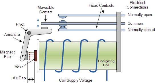
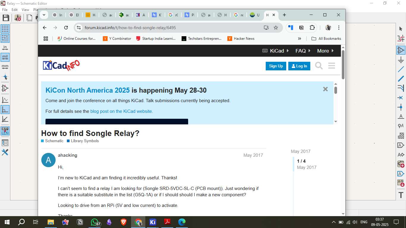
A relay is an electrically operated switch that uses an electromagnet to mechanically operate a switch. It allows a low-power microcontroller signal to control a higher-power circuit. Relays are widely used in automation, control systems, and electrical protection circuits. In this assignment, the relay module is connected to a microcontroller to demonstrate its control through code.
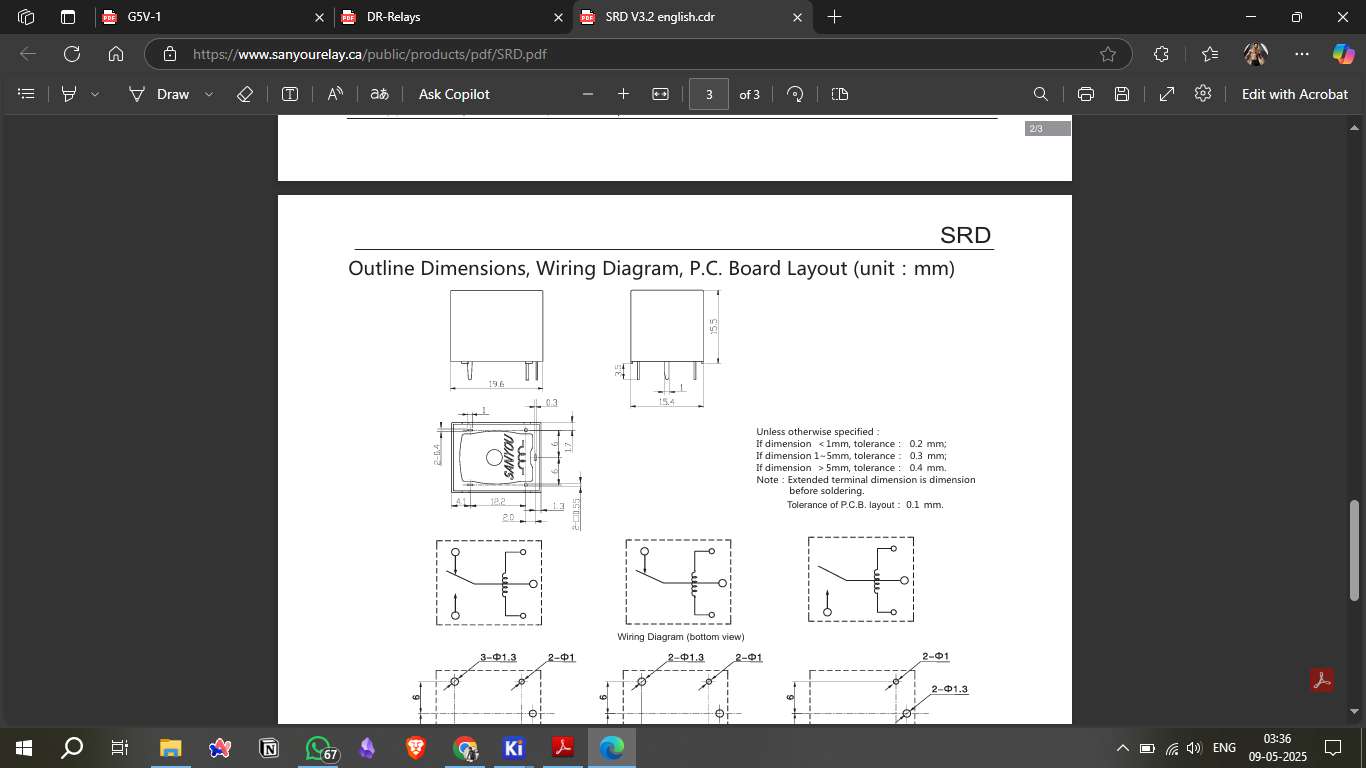
2. Understanding the Relay
Relays are critical components for controlling high-current devices with low-power control signals. They consist of several key elements: an electromagnet that activates the switch when energized, an armature that moves in response to the electromagnetic force, contacts that connect and disconnect the controlled circuit, and a spring that returns the armature to its original position when the electromagnet is de-energized. Together, these components allow the relay to function as a powerful, electrically controlled switch for various applications.
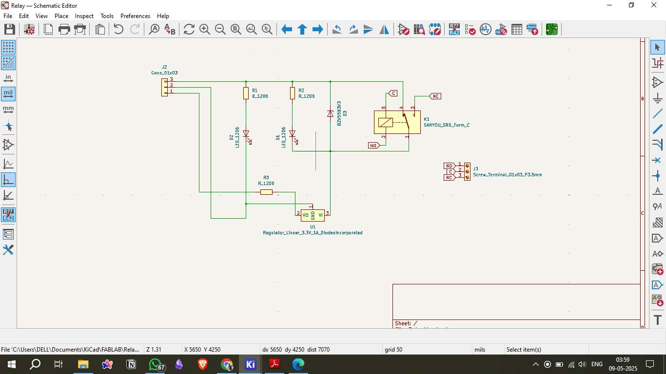
3. Circuit Diagram
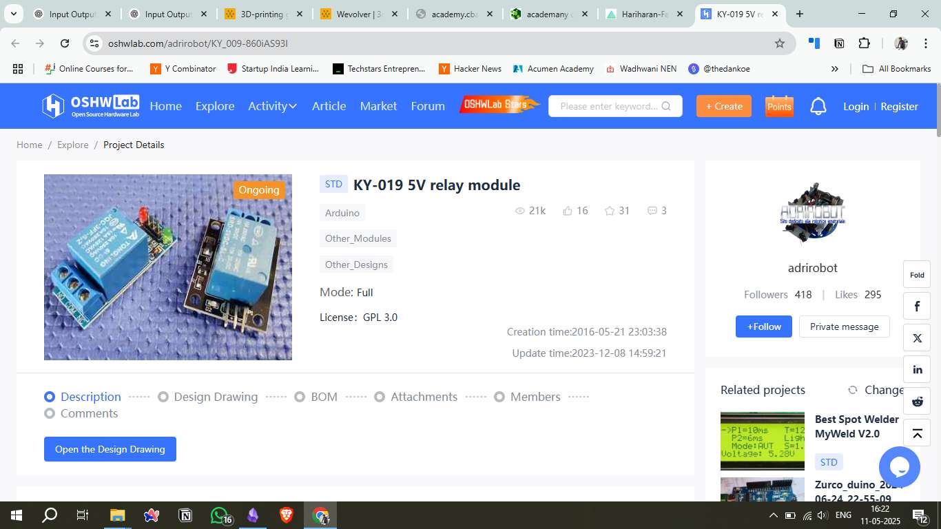
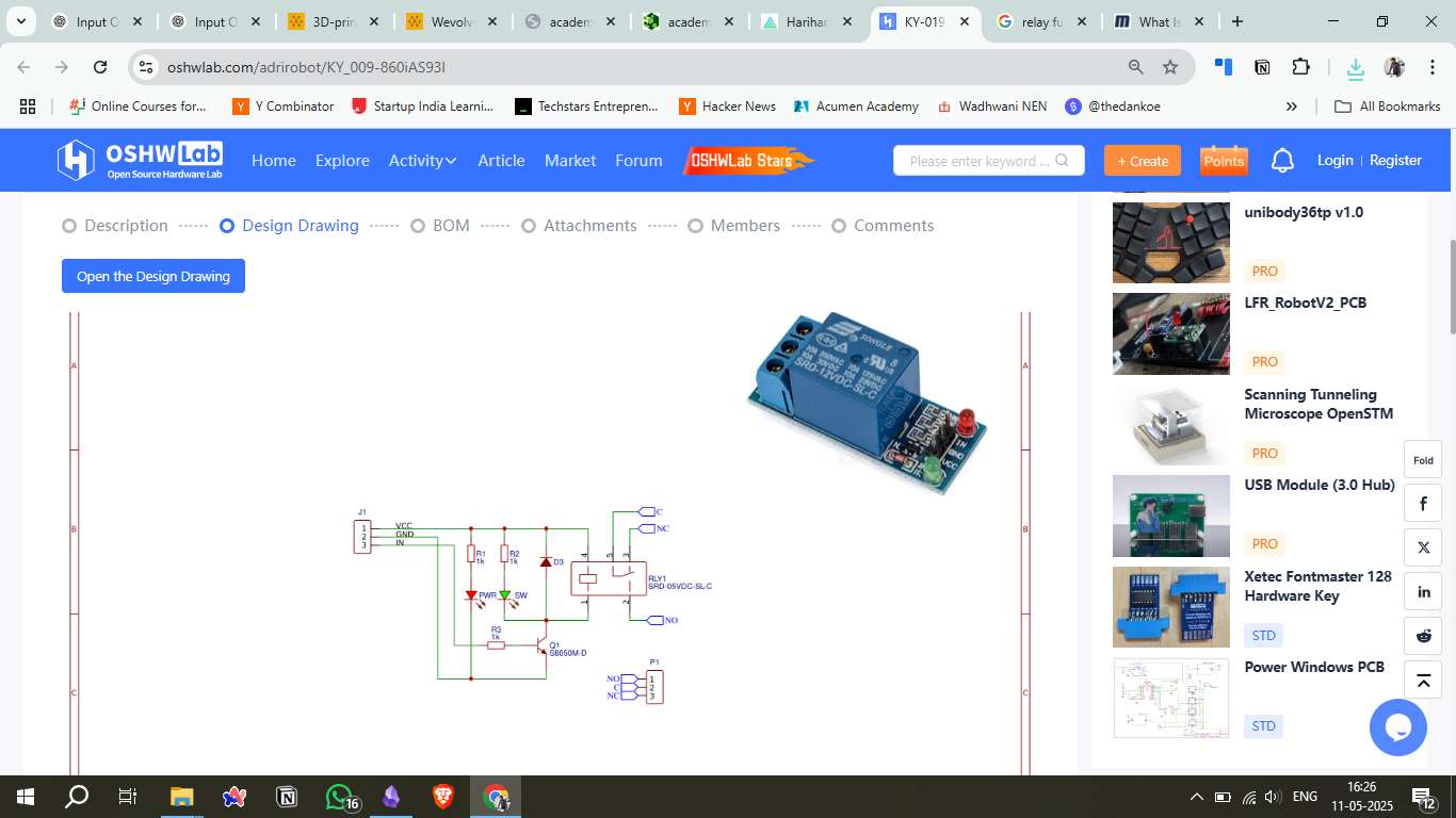
The circuit design includes a relay module connected to a microcontroller (e.g., Seeed Studio Xiao). The data pin of the relay is connected to a digital output pin, while the power (VCC) and ground (GND) connections are established to power the relay module.
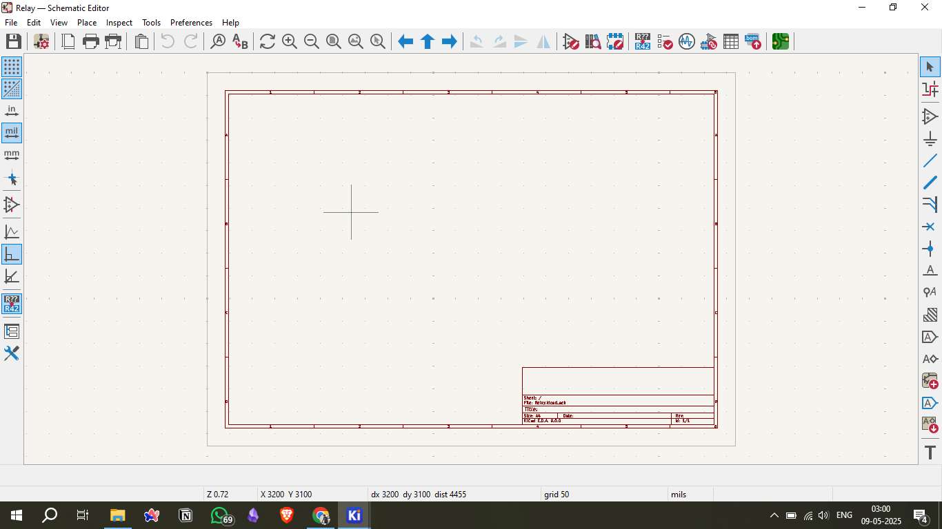
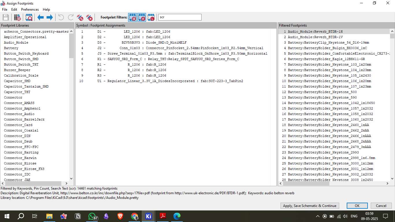
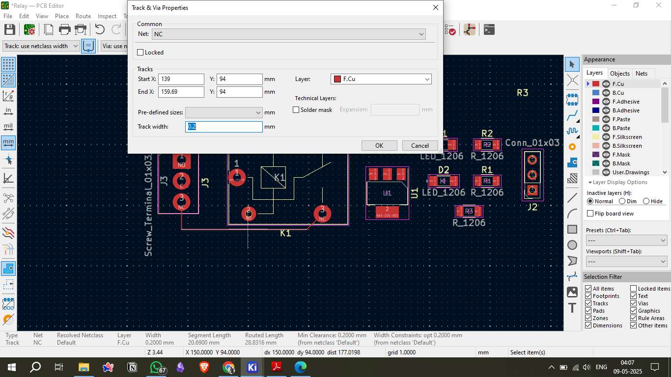
4. Board Design in KiCad
Designing the relay module PCB in KiCad involves several steps. First, create the schematic diagram to define the electrical connections. Then, assign appropriate footprints to each component, route the copper traces to connect the components, and define power planes for stable power distribution. Finally, run an Electrical Rules Check (ERC) to validate the design and ensure there are no critical errors.
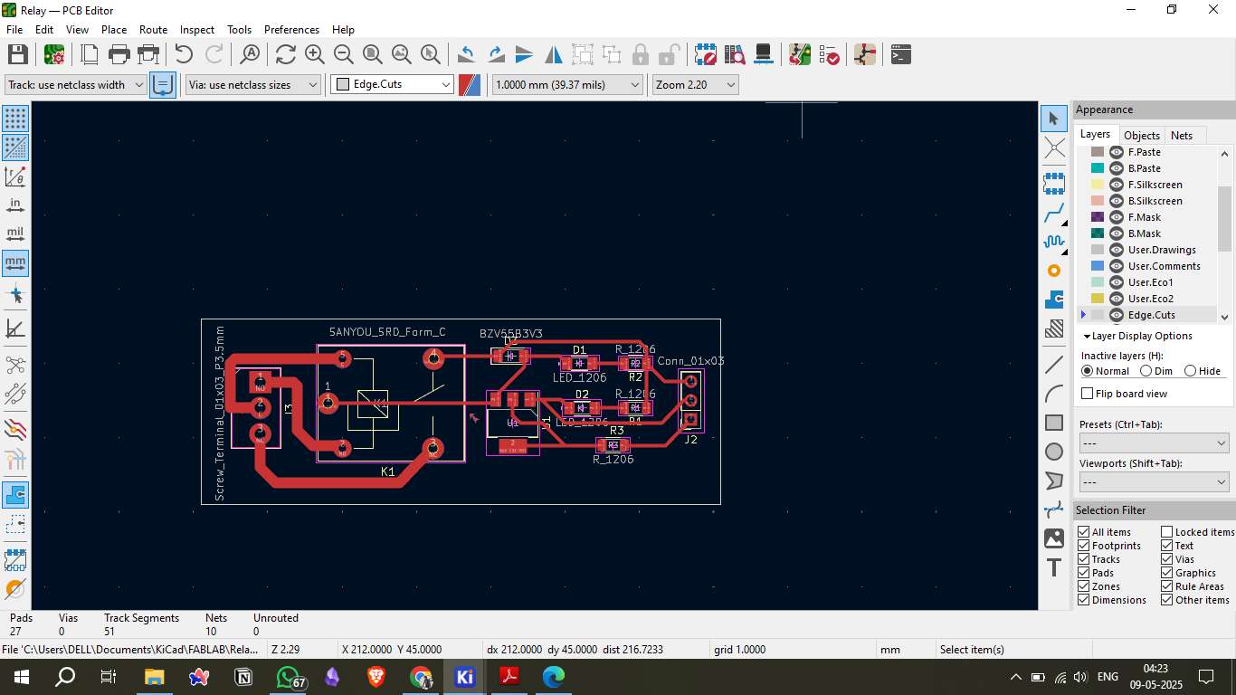
5. Placing Components
After designing the schematic, the components are placed on the PCB layout based on the schematic connections. Key components include the relay, current-limiting resistor for the relay coil, flyback diode for protection, and header pins for microcontroller connection. Proper placement is crucial to ensure signal integrity and reduce electromagnetic interference.
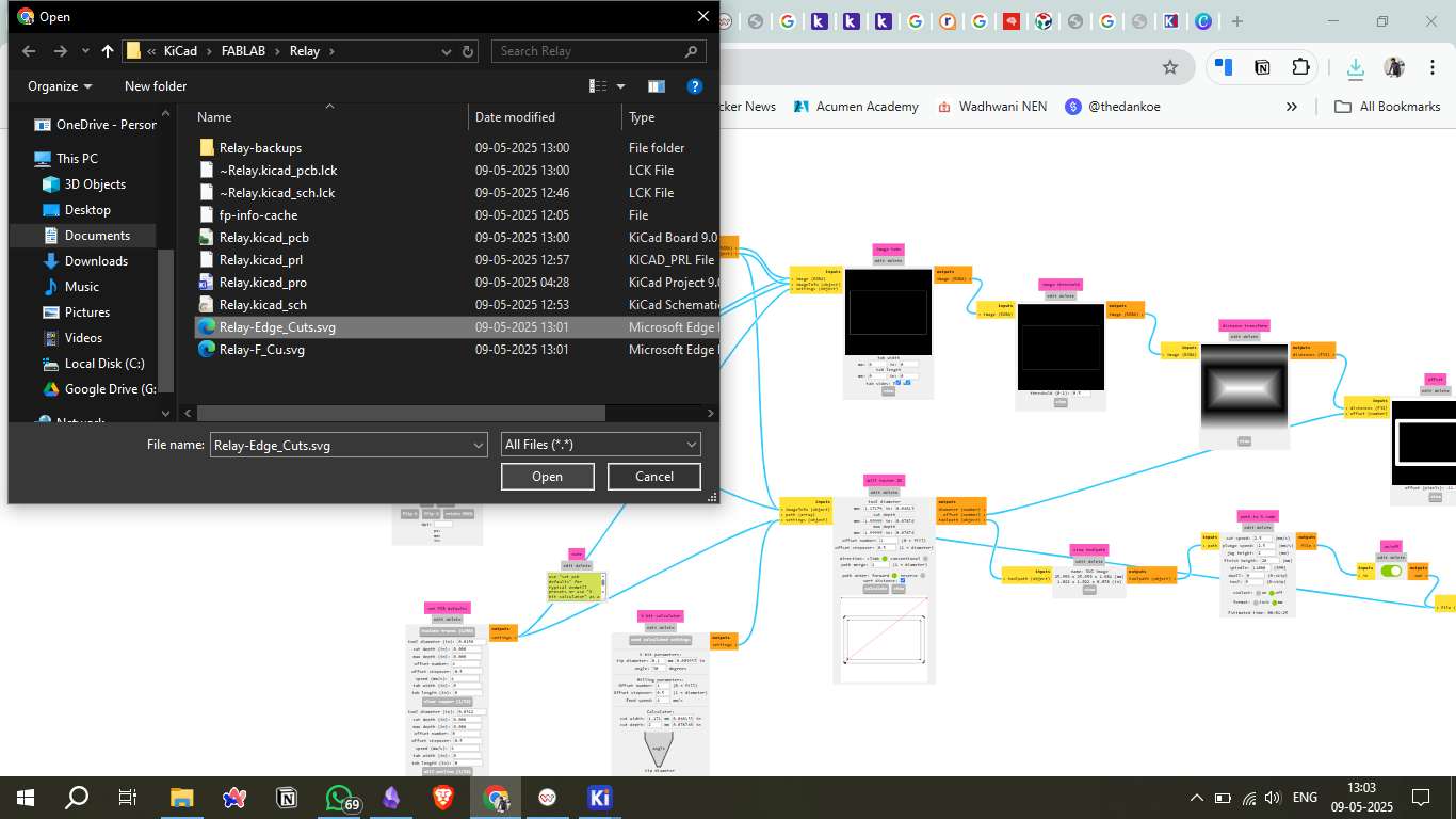
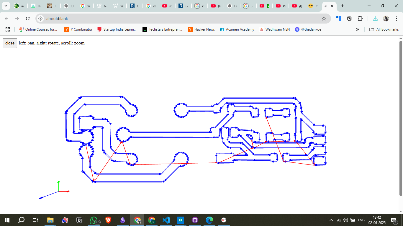
6. Generating PCB Files
Once the design is complete, generate the Gerber files required for PCB manufacturing. These files contain the information needed for the PCB milling machine to cut and etch the copper traces. Additionally, export the PCB layout as SVG files for use in the milling software.
7. Converting SVG to G-code (Mods CE)
Convert the SVG files into G-code using the Mods CE software. This step is essential for converting the design into machine-readable instructions. Key parameters like cut depth, feed rate, and spindle speed must be correctly set to ensure precise milling.
8. Machine and Copper Plate Setup
Mount the copper plate onto the milling machine bed, ensuring it is securely fixed and properly aligned. Set the milling tool’s zero position to the lower-left corner of the copper plate to ensure accurate cutting.

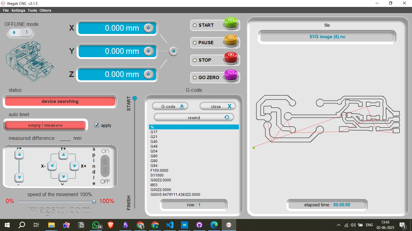
9. Uploading to Wegstr Software
Upload the generated G-code file to the Wegstr software for final milling preparation. Verify that the spindle speed, cut depth, and origin position are correctly configured before starting the milling process.
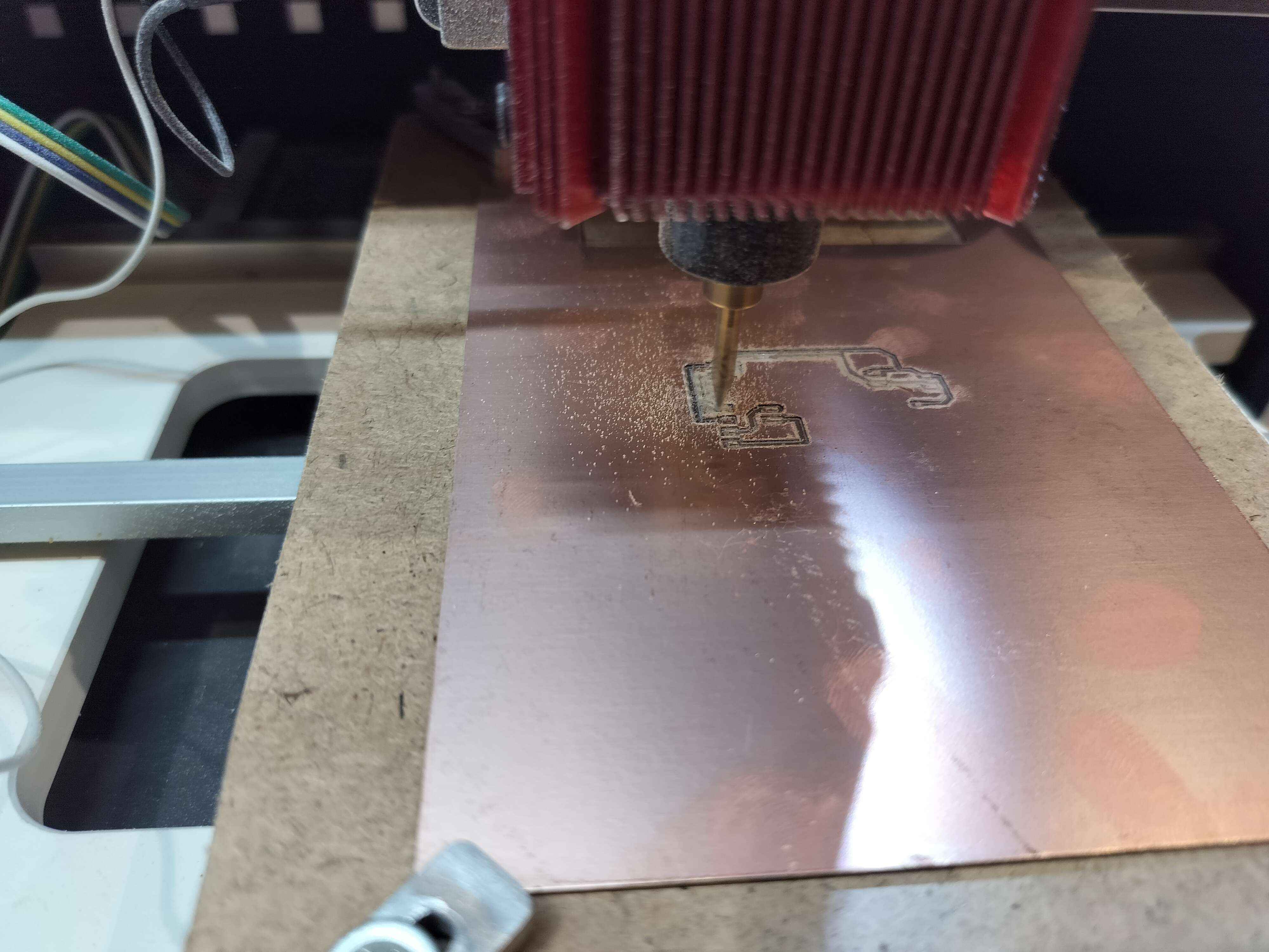
10. Milling and Soldering
Begin the milling process. Once complete, carefully inspect the milled board for electrical continuity and potential shorts. After confirming the board’s integrity, solder the components, ensuring each joint is solid and reliable for long-term performance.
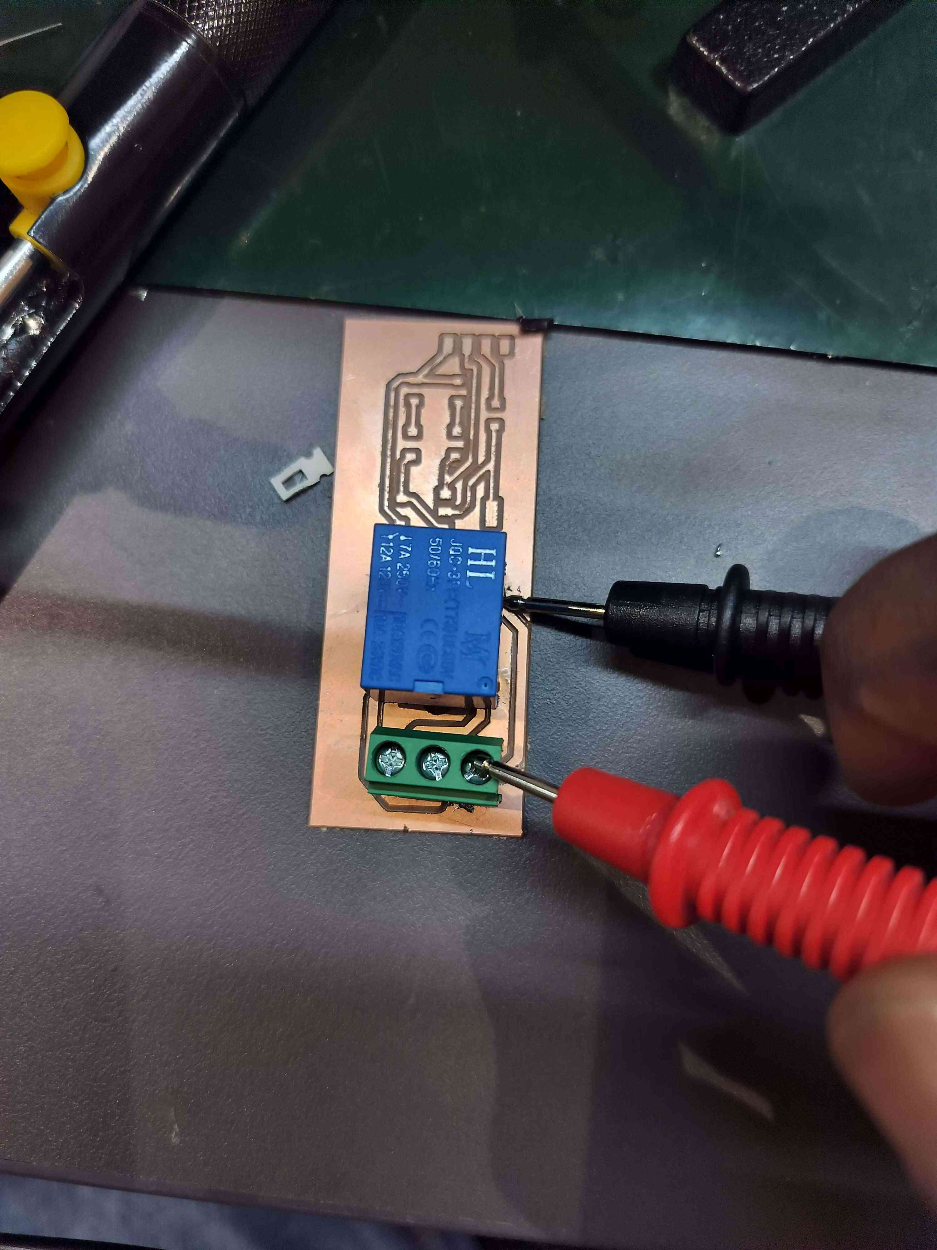
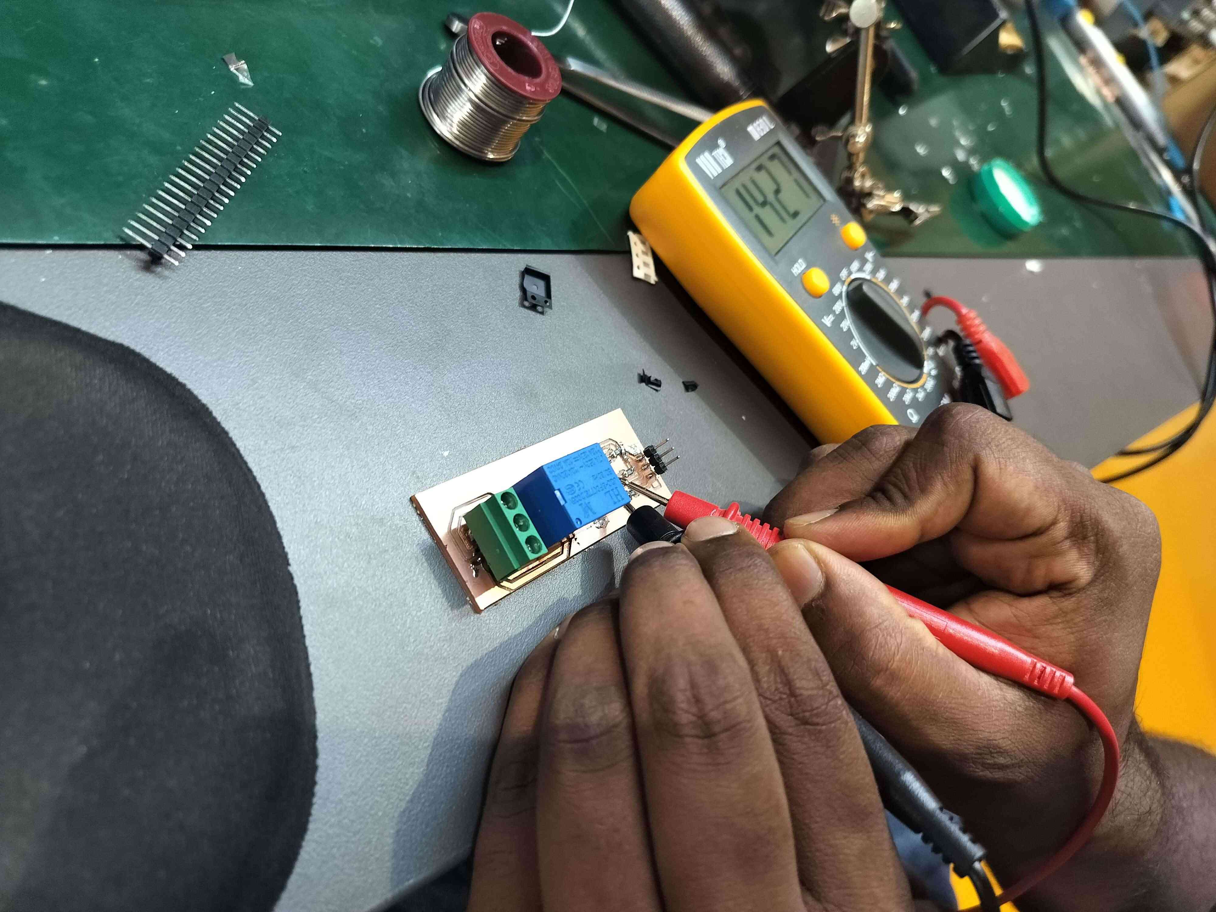
11. Testing the Component
After soldering, test the board for electrical continuity using a multimeter. Verify that the relay coil energizes as expected and that the contacts switch correctly when activated.
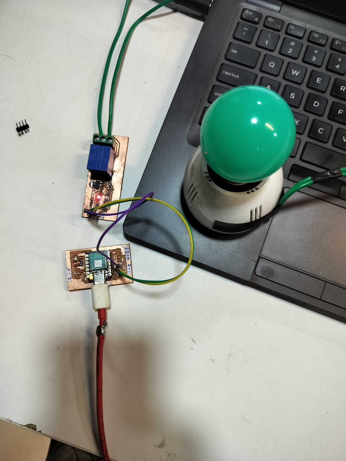
12. Connecting to the Microcontroller
Connect the completed relay module to the microcontroller using header pins. Double-check that the data pin, VCC, and GND connections are correctly made to avoid damage to the microcontroller or relay.
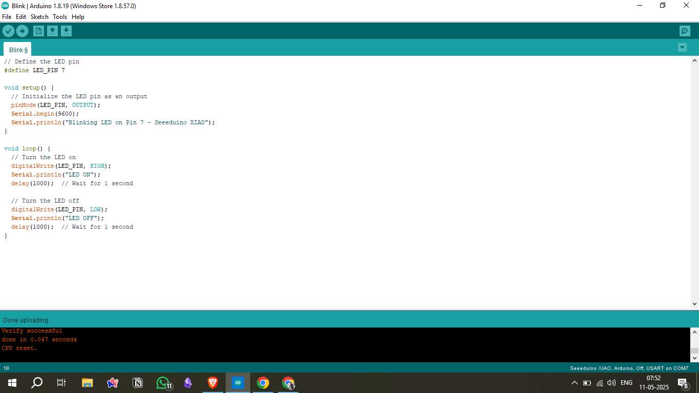
13. Uploading Code
Write and upload the necessary code to control the relay through the microcontroller. This code should enable you to control the relay’s on and off states using digital output signals from the microcontroller.
14. Result Video
Capture a demonstration video showcasing the completed relay module in action, highlighting its performance and functionality.
Seeed Relay Control Code
This Arduino code is compatible with Arduino IDE and Seeed boards (XIAO, Wio Terminal, etc.) for controlling relays through serial commands, auto-toggle functionality, and button control options.
// Seeed Relay Control Code
            // Compatible with Arduino IDE and Seeed boards (XIAO, Wio Terminal, etc.)

            // Pin Configuration
            const int RELAY_PIN = 2;  // Change this to your actual relay pin
            const int LED_PIN = 13;   // Built-in LED for status indication

            void setup() {
              // Initialize serial communication
              Serial.begin(9600);

              // Initialize pins
              pinMode(RELAY_PIN, OUTPUT);
              pinMode(LED_PIN, OUTPUT);

              // Start with relay OFF
              digitalWrite(RELAY_PIN, LOW);
              digitalWrite(LED_PIN, LOW);

              Serial.println("Seeed Relay Control Ready!");
              Serial.println("Commands:");
              Serial.println("1 or ON - Turn relay ON");
              Serial.println("0 or OFF - Turn relay OFF");
              Serial.println("T or TOGGLE - Toggle relay state");
            }

            void loop() {
              // Check for serial commands
              if (Serial.available() > 0) {
                String command = Serial.readString();
                command.trim(); // Remove whitespace
                command.toUpperCase(); // Convert to uppercase

                if (command == "1" || command == "ON") {
                  turnRelayOn();
                }
                else if (command == "0" || command == "OFF") {
                  turnRelayOff();
                }
                else if (command == "T" || command == "TOGGLE") {
                  toggleRelay();
                }
                else {
                  Serial.println("Invalid command. Use: ON, OFF, or TOGGLE");
                }
              }

              // Auto toggle demo (uncomment to enable)
              // autoToggleDemo();
            }

            void turnRelayOn() {
              digitalWrite(RELAY_PIN, HIGH);
              digitalWrite(LED_PIN, HIGH);
              Serial.println("Relay ON");
            }

            void turnRelayOff() {
              digitalWrite(RELAY_PIN, LOW);
              digitalWrite(LED_PIN, LOW);
              Serial.println("Relay OFF");
            }

            void toggleRelay() {
              int currentState = digitalRead(RELAY_PIN);
              if (currentState == HIGH) {
                turnRelayOff();
              } else {
                turnRelayOn();
              }
            }

            // Optional: Auto toggle function for testing
            void autoToggleDemo() {
              static unsigned long lastToggle = 0;
              const unsigned long toggleInterval = 2000; // 2 seconds

              if (millis() - lastToggle >= toggleInterval) {
                toggleRelay();
                lastToggle = millis();
              }
            }

            // Alternative: Button control function
            void buttonControl() {
              const int BUTTON_PIN = 3; // Add button to pin 3
              static bool lastButtonState = HIGH;
              static bool currentButtonState = HIGH;
              static unsigned long lastDebounceTime = 0;
              const unsigned long debounceDelay = 50;

              // Read button state
              int reading = digitalRead(BUTTON_PIN);

              // Debounce button
              if (reading != lastButtonState) {
                lastDebounceTime = millis();
              }

              if ((millis() - lastDebounceTime) > debounceDelay) {
                if (reading != currentButtonState) {
                  currentButtonState = reading;

                  // Button pressed (assuming pullup resistor)
                  if (currentButtonState == LOW) {
                    toggleRelay();
                  }
                }
              }

              lastButtonState = reading;
            }
Source Files
Tools & Platforms Used
Mods CE: SVG to G-code conversion - https://modsproject.org/
KiCad: Schematic and PCB design - https://kicad.org/
Arduino IDE: Microcontroller programming - https://arduino.cc
Seeeduino XIAO Docs: Board reference - XIAO Wiki
Table of Contents
- Assignment: Output Devices
- 1. Working Principle
- 2. Understanding the Relay
- 3. Circuit Diagram
- 4. Board Design in KiCad
- 5. Placing Components
- 6. Generating PCB Files
- 7. Converting SVG to G-code
- 8. Machine Setup
- 9. Uploading to Wegstr
- 10. Milling and Soldering
- 11. Testing the Component
- 12. Connecting Microcontroller
- 13. Uploading Code
- 14. Result Video
- Seeed Relay Control Code
- Source Files
- Tools & Platforms Used