
Week 9
Assignment: Input Devices
Group assignment
The Link of Group assignments.
Individual assignment
measure something: add a sensor to a microcontroller board that you have designed and read it
1. Working Principle
The DHT11 sensor is a low-cost digital temperature and humidity sensor. It uses a capacitive humidity sensor and a thermistor to measure the surrounding air and outputs a digital signal on the data pin. It operates on a simple one-wire protocol, making it easy to interface with microcontrollers. The sensor has three pins: VCC, GND, and DATA. The DATA pin transmits the measured temperature and humidity in a single burst.
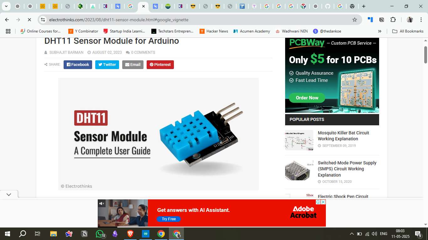
2. DHT11 Sensor Overview
The DHT11 sensor is widely used for temperature and humidity monitoring. It can measure temperature from 0 to 50°C with ±2°C accuracy and humidity from 20 to 80% with ±5% accuracy. It is preferred for its ease of use, affordability, and relatively accurate measurements within its operational range.
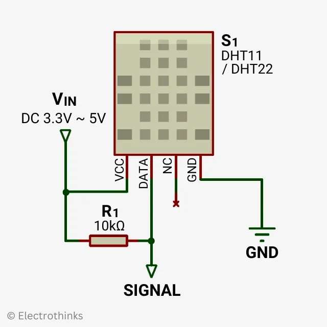
3. Circuit Diagram
The circuit diagram for the DHT11 sensor interfaced with the microcontroller is designed in KiCad. The data pin of the DHT11 is connected to the digital input of the microcontroller (D3), while VCC and GND are connected to the respective power supply pins. A pull-up resistor of 10kΩ is placed between the data pin and VCC to ensure stable signal transmission.
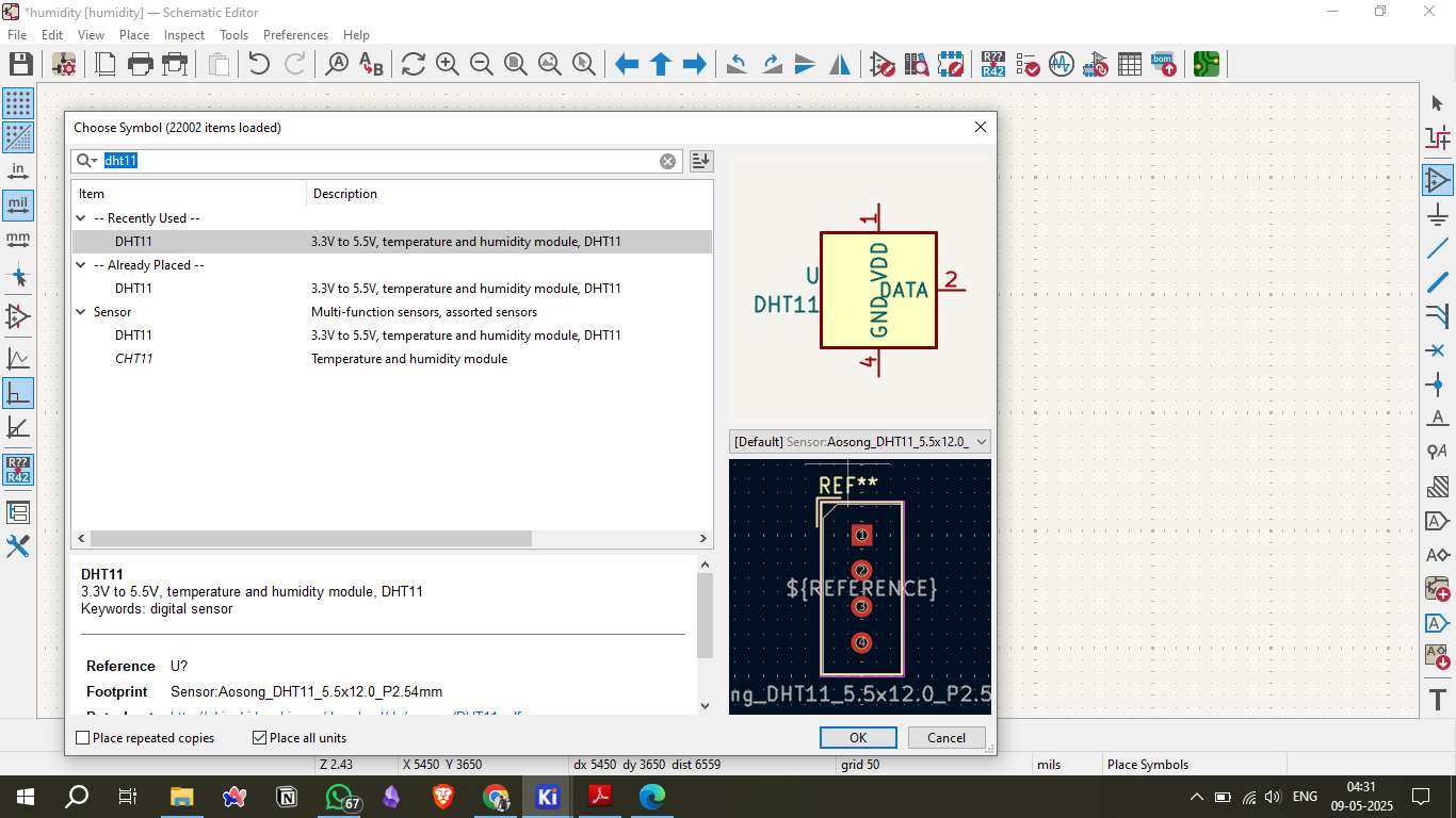
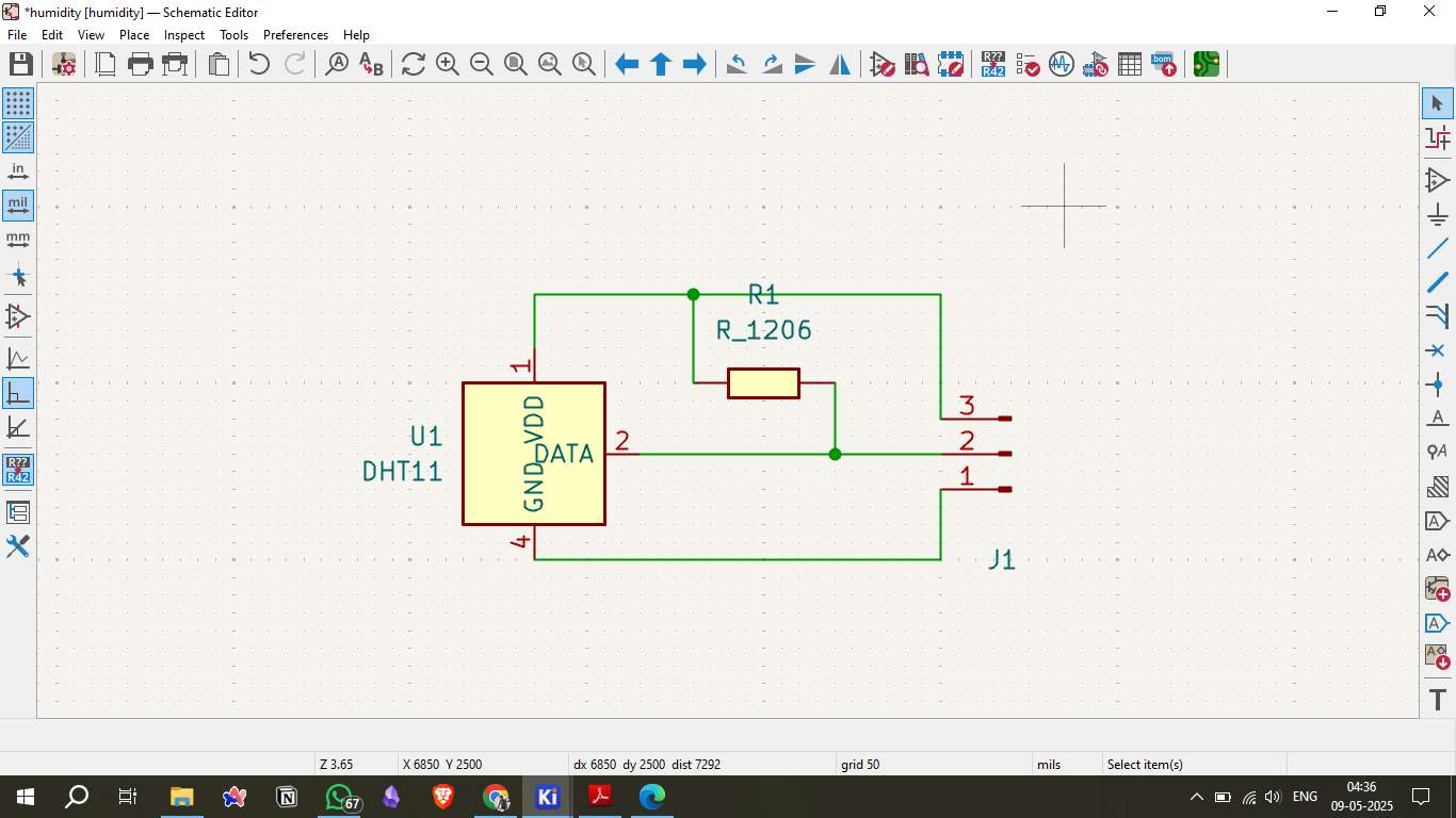
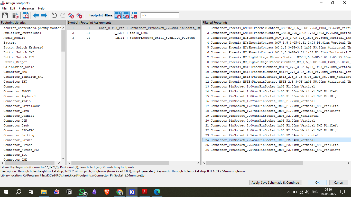
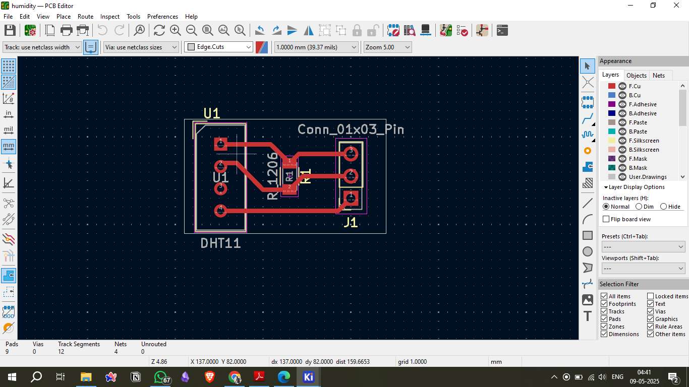
4. Board Design in KiCad
To design the board, I used KiCad's schematic editor to place the DHT11 sensor, microcontroller pins, and other components. After completing the schematic, I proceeded to the PCB layout, arranging the components compactly and optimizing the trace routes for minimal interference.
5. Placing Components
The components, including headers for power and data, were placed considering spacing and easy soldering. The DHT11 sensor was positioned for optimal access to the data pin, with appropriate clearance for soldering.
6. Generating the PCB File
After finalizing the layout, I generated the Gerber files and drill files. These files contain the necessary information for PCB milling, including the top copper layer, edge cuts, and drill holes.
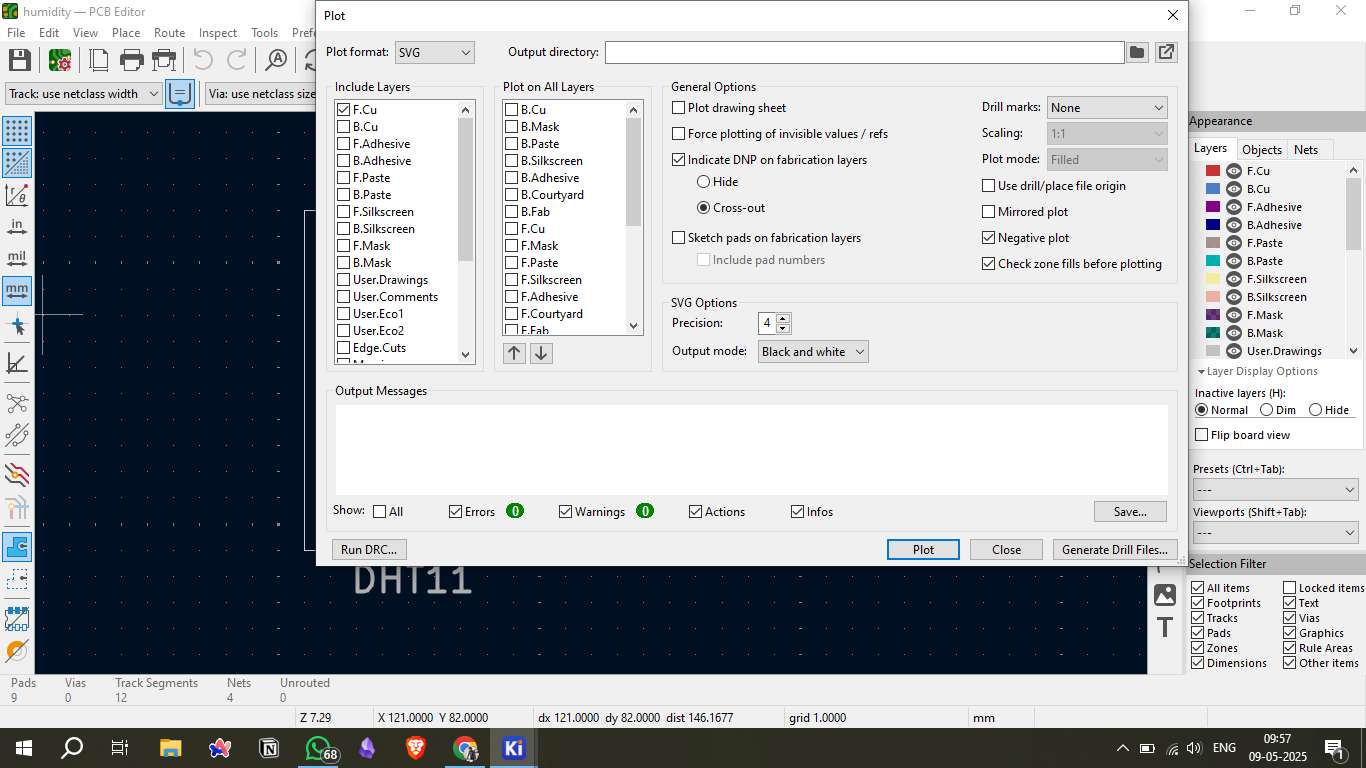
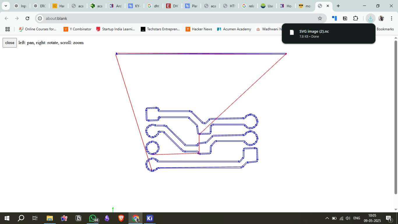
7. Save as SVG Files
The generated Gerber files were converted to SVG format using KiCad's export options. SVG format is essential for further processing into G-code.
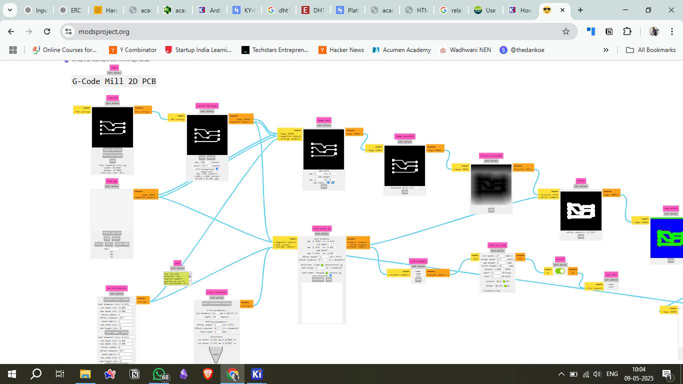
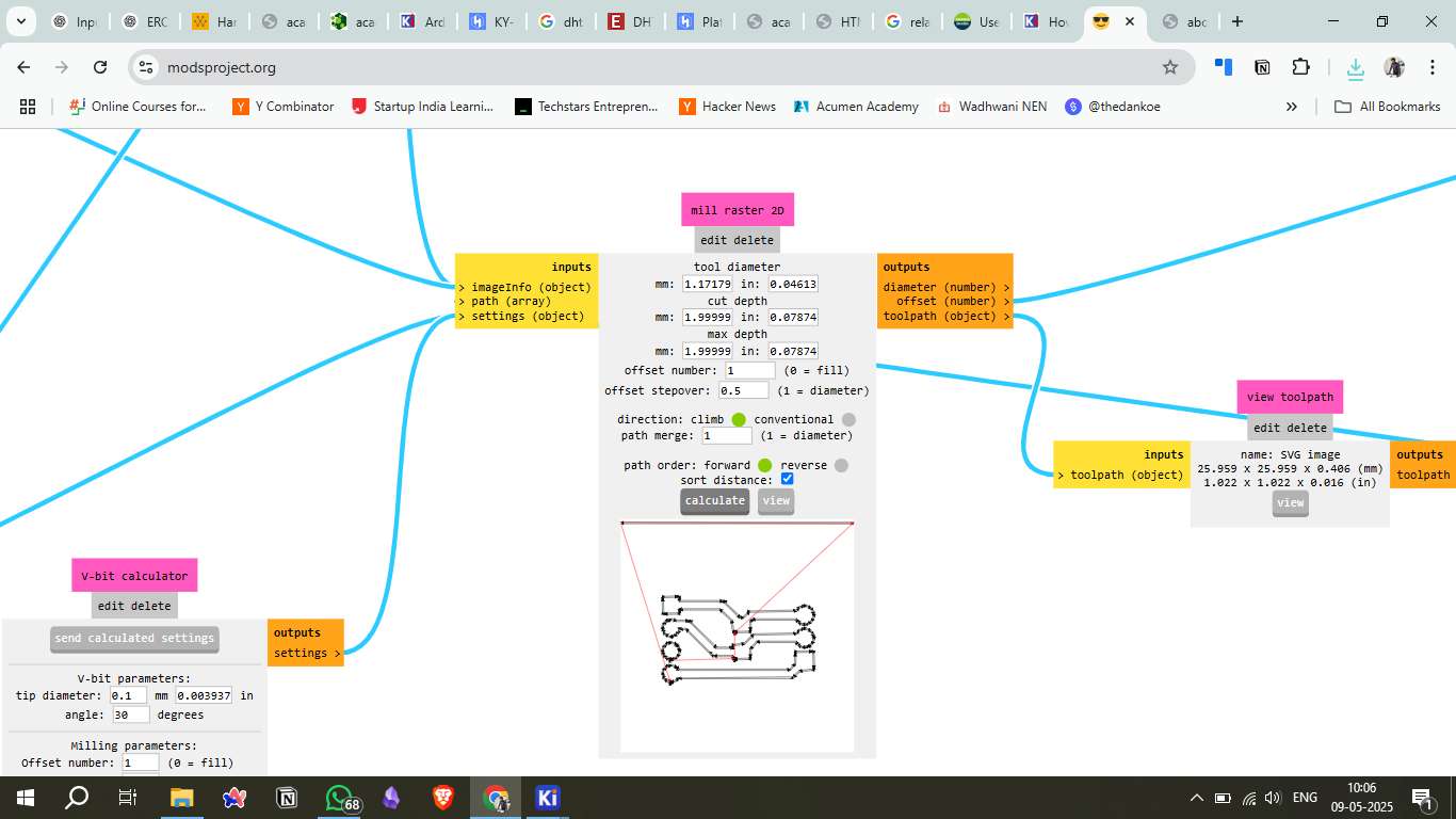
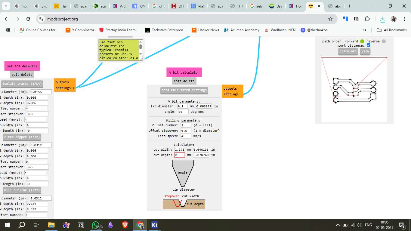
8. Converting SVG to G-code (Mods CE)
Mods CE was used to convert the SVG files into G-code compatible with the milling machine. This step involves selecting the correct toolpath settings, including cutting depth, tool diameter, and feed rate.
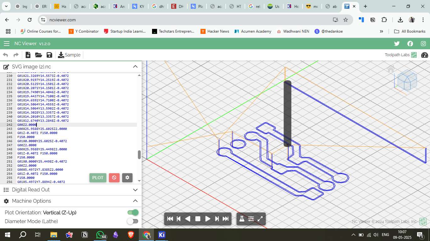
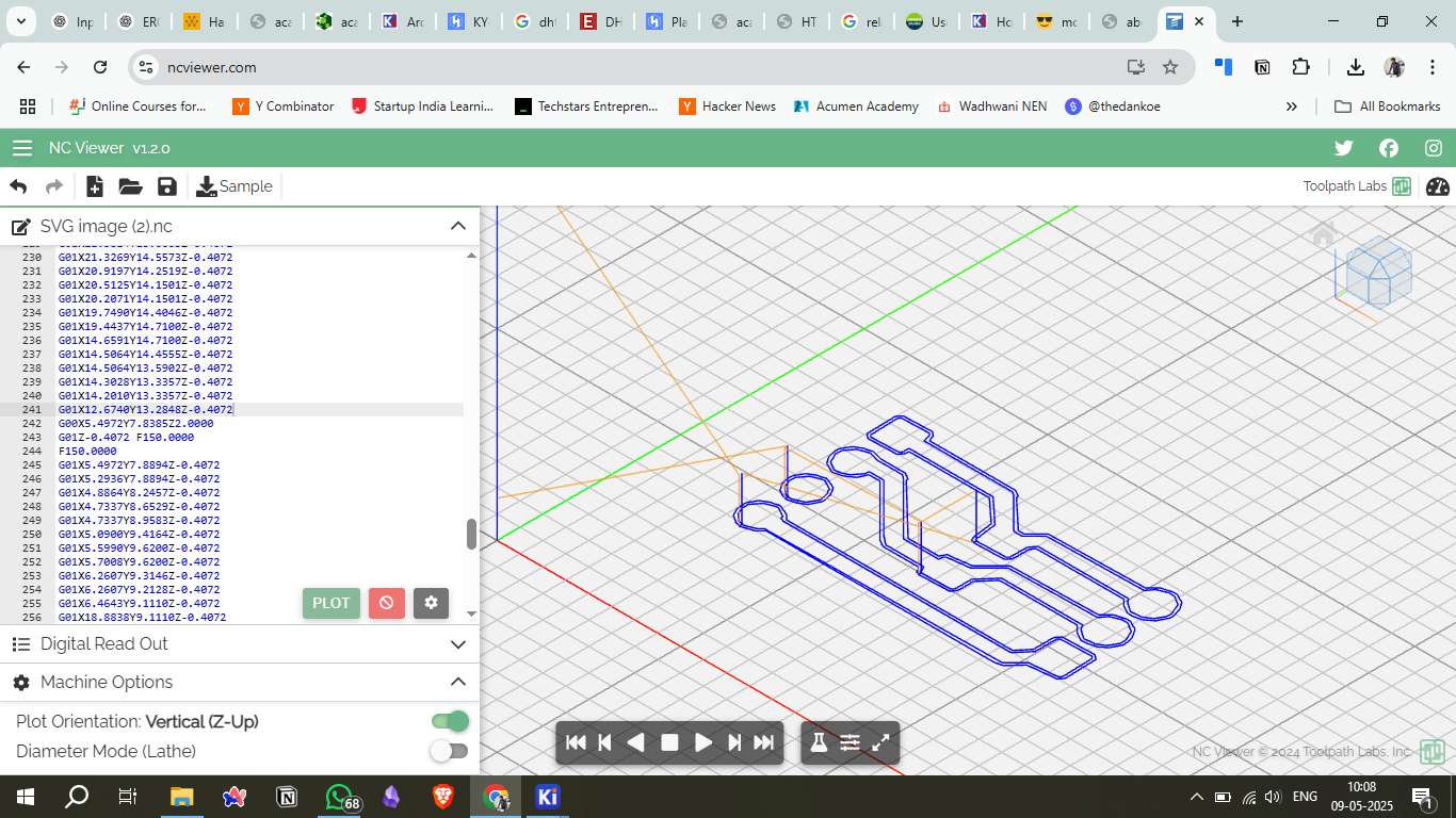
9. NC Viewer Edit
The generated G-code was verified and edited using NC Viewer to ensure proper formatting and trajectory. Adjustments were made to the feed rate and cutting speed where necessary.
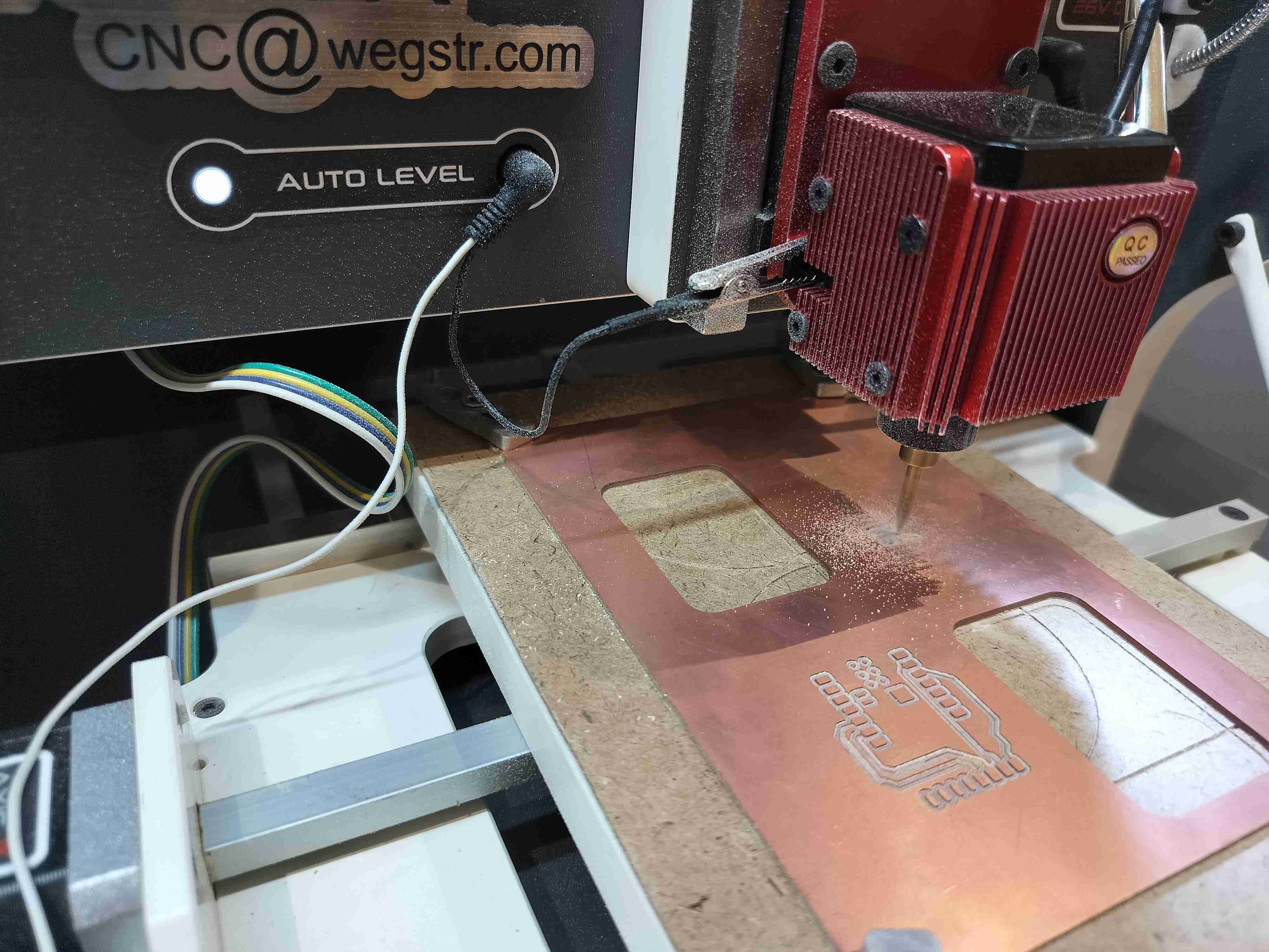
10. Machine and Copper Plate Setup
The copper plate was mounted on the milling machine bed and properly aligned. The milling tool was calibrated, and the zero position was set to the bottom-left corner of the copper plate.
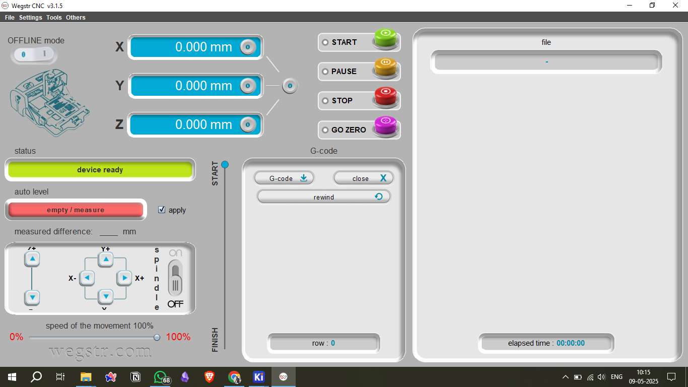
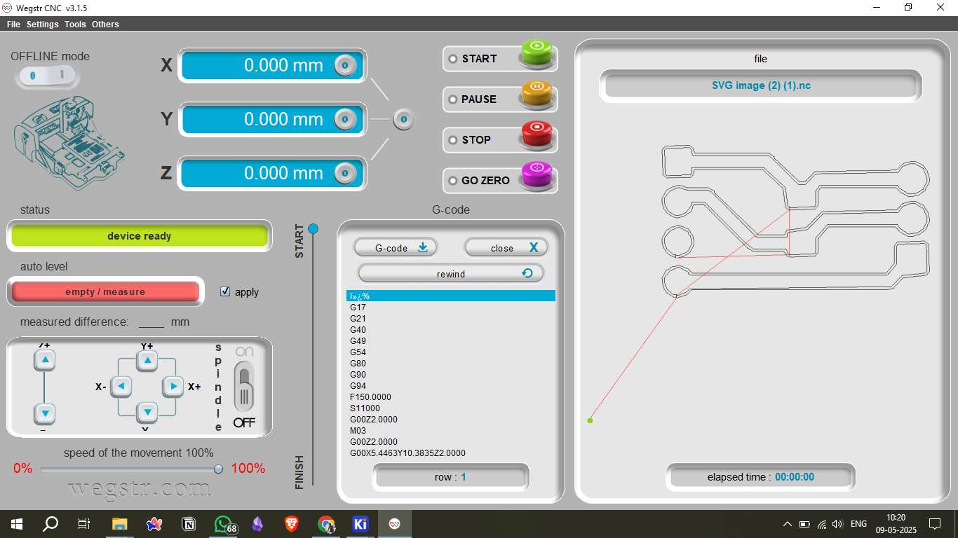
11. Uploading to Wegstr Software
The G-code file was uploaded to the Wegstr software, where additional configuration settings, such as spindle speed and cut depth, were verified before starting the milling process.
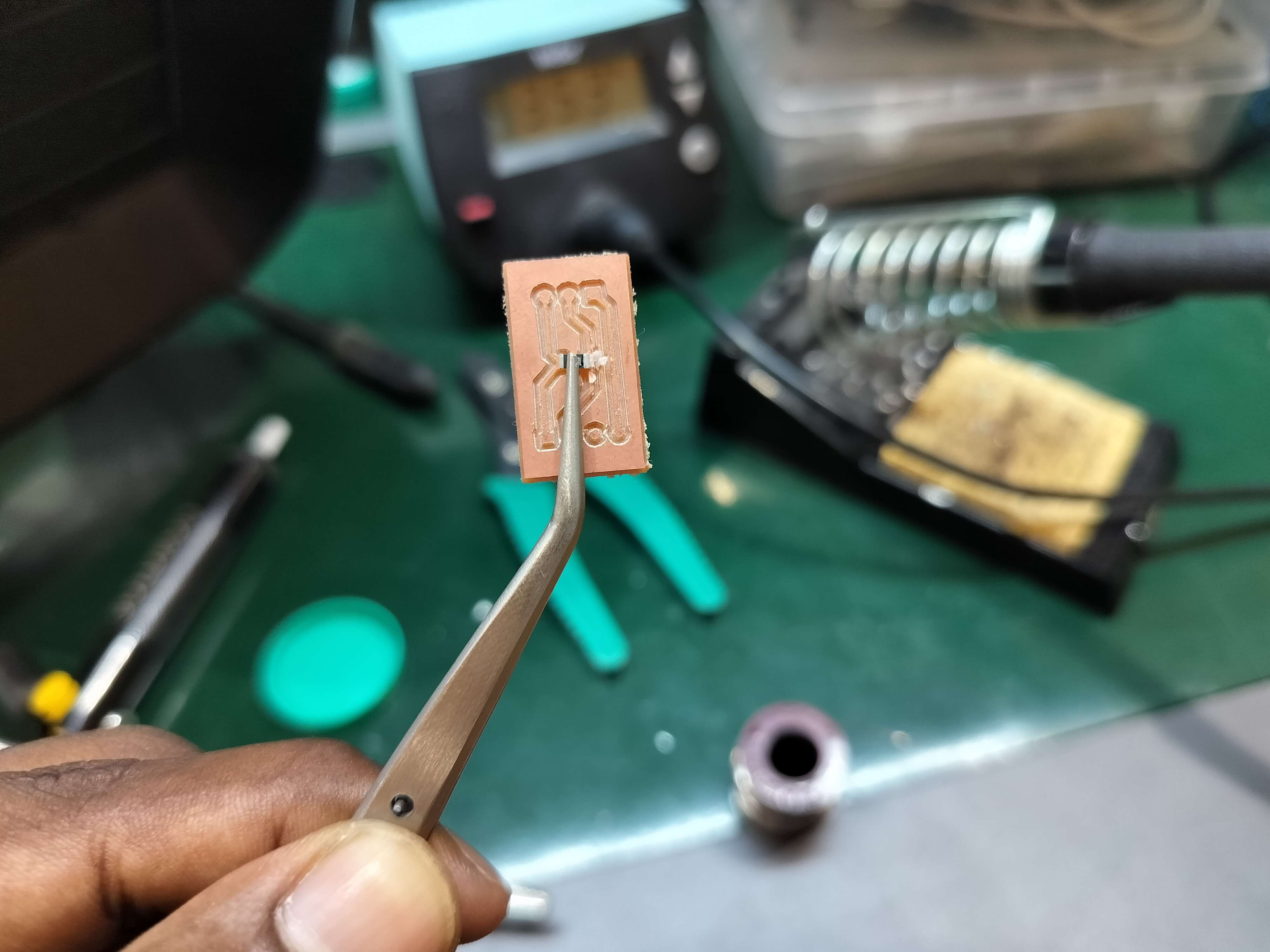
12. Milling and Soldering
After milling, the board was inspected for continuity and shorts. The DHT11 sensor and other components were soldered onto the board, ensuring solid connections.
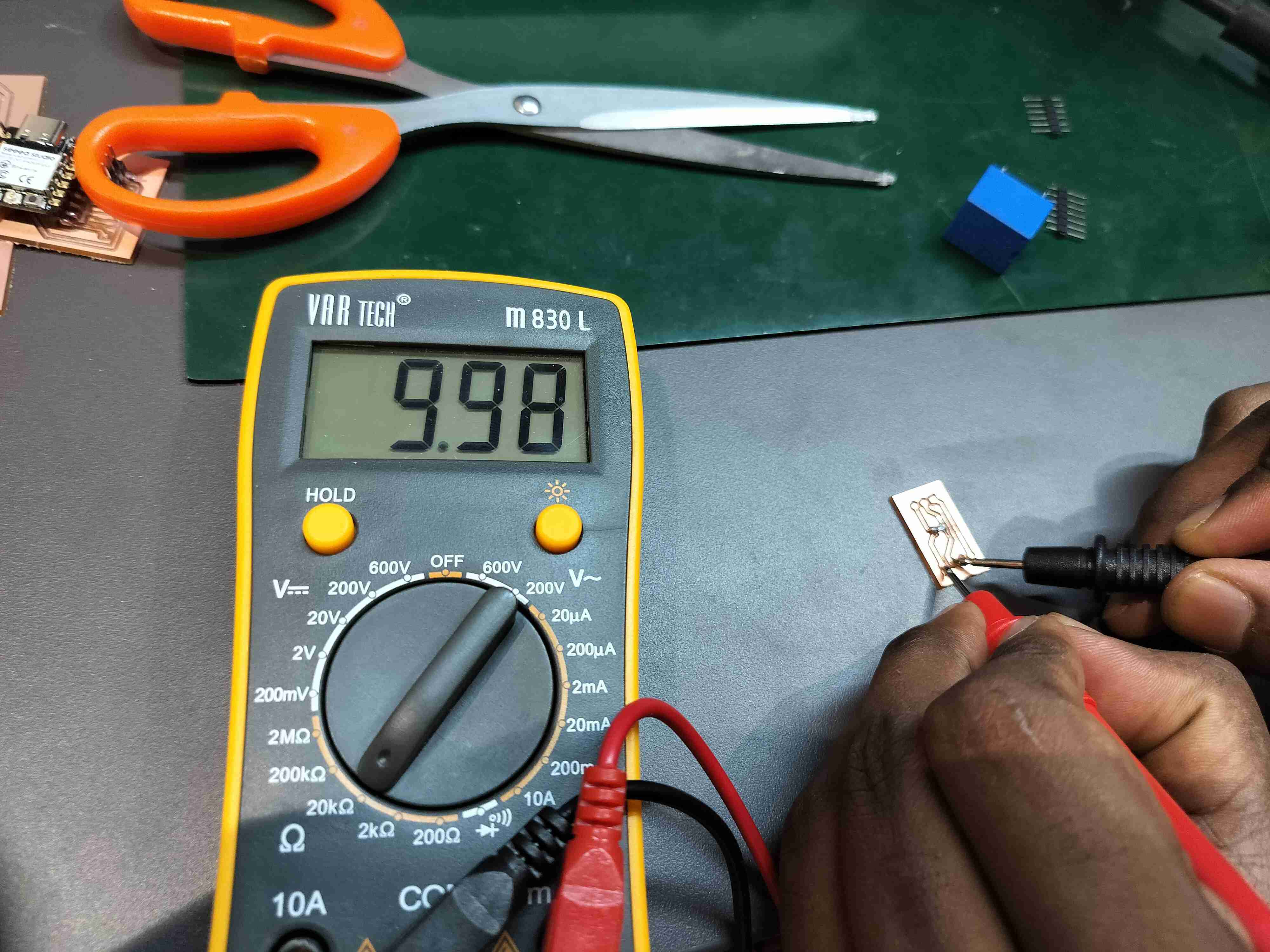
13. Testing the Component
The soldered board was tested for electrical continuity using a multimeter. The data pin of the DHT11 was checked for signal output to confirm proper connectivity.
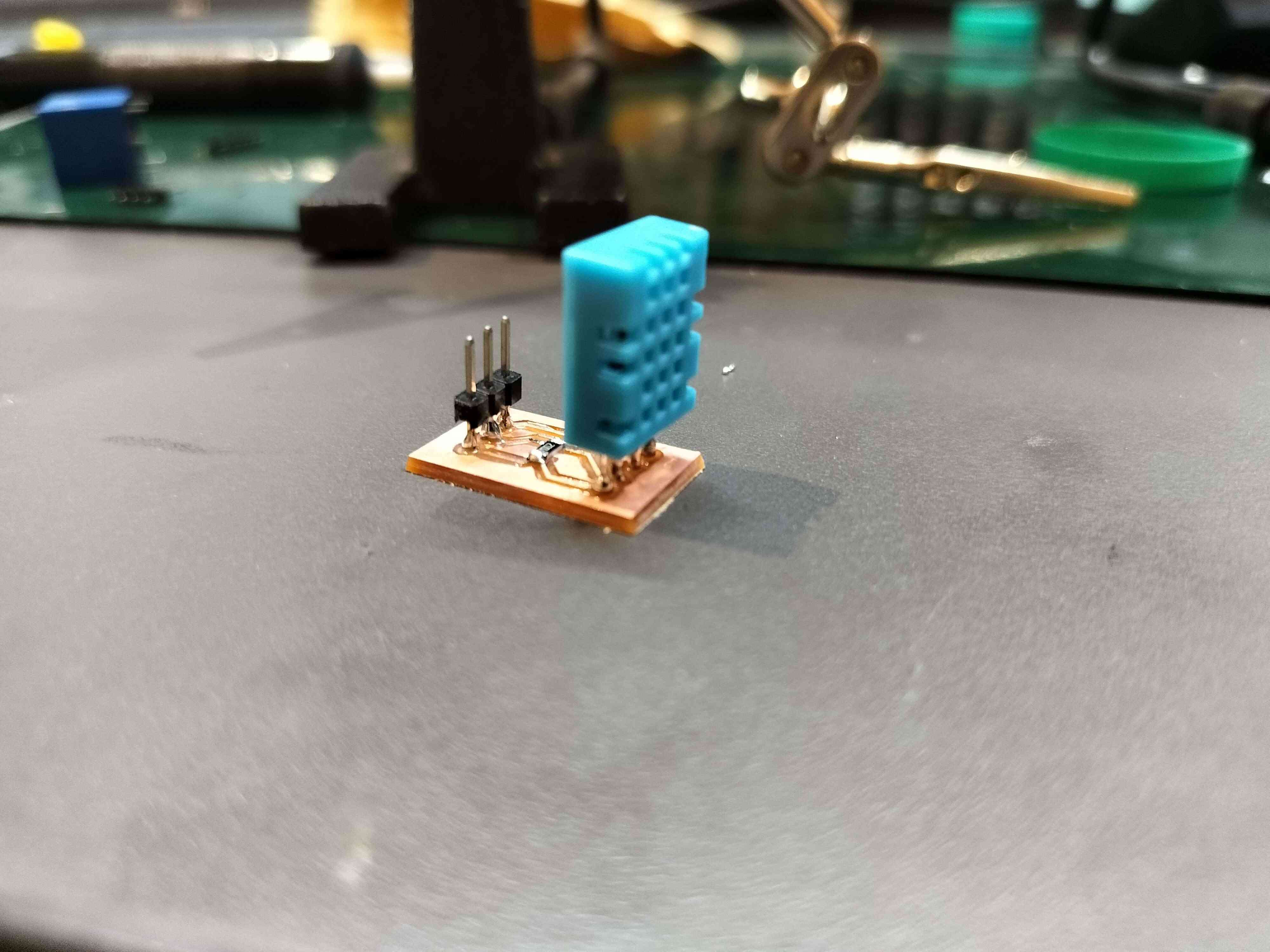
14. Connecting to the Microcontroller
The board was connected to the microcontroller using header pins. The DHT11 data pin was linked to digital pin D3 of the microcontroller, while power and ground connections were established.
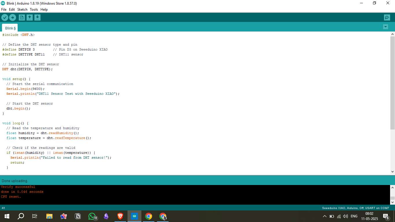
Source Code Example
#include "DHT.h"


#define DHTPIN 2
#define DHTTYPE DHT11


DHT dht(DHTPIN, DHTTYPE);

void setup() {
  Serial.begin(115200);
  Serial.println("DHT11 Temperature and Humidity Sensor Test");

  dht.begin();

  delay(2000);
}

void loop() {

  delay(2000);


  float humidity = dht.readHumidity();
  float temperature = dht.readTemperature();
  float temperatureF = dht.readTemperature(true);


  if (isnan(humidity) || isnan(temperature) || isnan(temperatureF)) {
    Serial.println("Failed to read from DHT sensor!");
    return;
  }

  // Compute heat index in Fahrenheit and Celsius
  float heatIndexF = dht.computeHeatIndex(temperatureF, humidity);
  float heatIndexC = dht.computeHeatIndex(temperature, humidity, false);

  // Print results to Serial Monitor
  Serial.println("--- DHT11 Sensor Readings ---");
  Serial.print("Humidity: ");
  Serial.print(humidity);
  Serial.println("%");

}
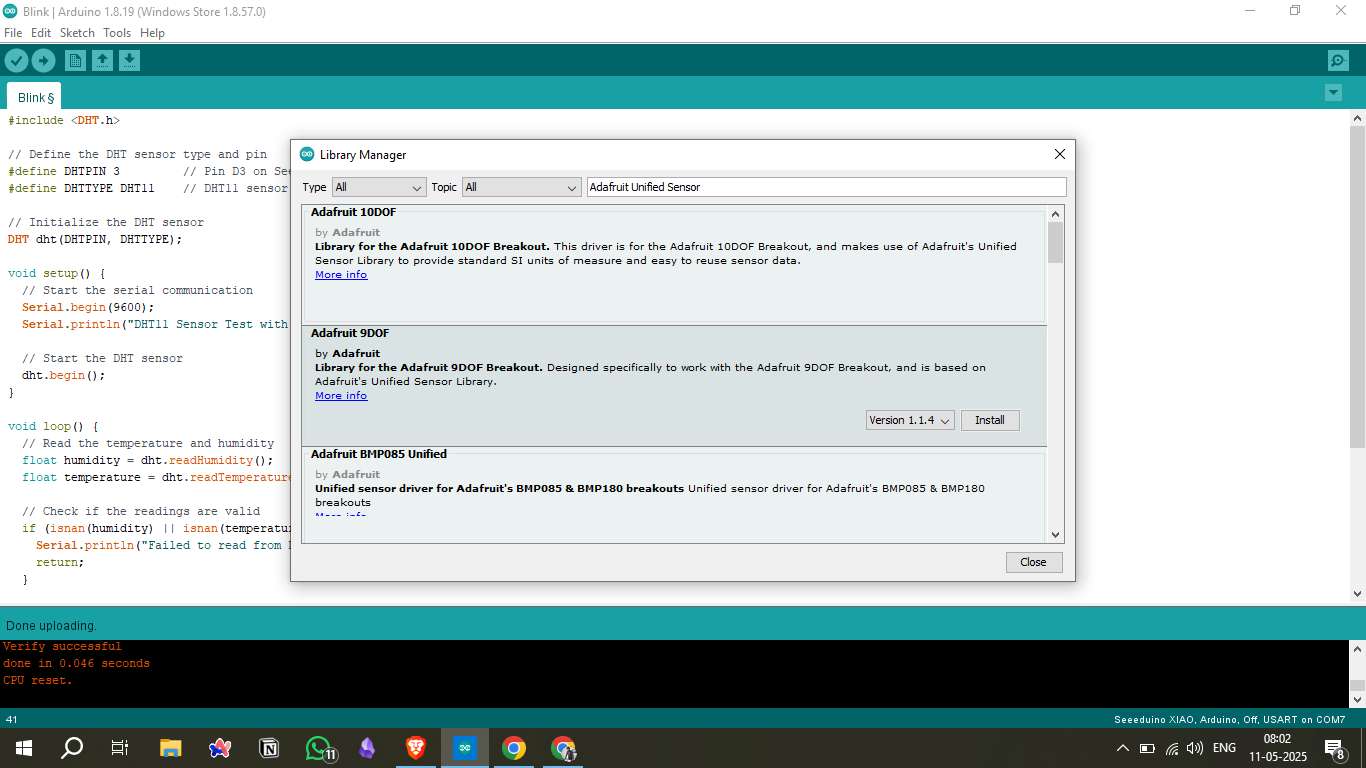
15. Uploading Code
The microcontroller was programmed using the Arduino IDE. The DHT11 library was included, and a simple sketch was written to read temperature and humidity data and print it to the serial monitor.
16. Result Video
A video was recorded showing the real-time temperature and humidity readings from the DHT11 sensor, displayed on the serial monitor.
Source Files
Tools & Platforms Used
Mods CE: SVG to G-code conversion - https://modsproject.org/
KiCad: Schematic and PCB design - https://kicad.org/
Arduino IDE: Microcontroller programming - https://arduino.cc
Seeeduino XIAO Docs: Board reference - XIAO Wiki
Table of Contents
- 1. Working Principle
- 2. DHT11 Sensor Overview
- 3. Circuit Diagram
- 4. Board Design in KiCad
- 5. Placing Components
- 6. Generating the PCB File
- 7. Save as SVG Files
- 8. Converting SVG to G-code
- 9. NC Viewer Edit
- 10. Machine and Copper Plate Setup
- 11. Uploading to Wegstr Software
- 12. Milling and Soldering
- 13. Testing the Component
- 14. Connecting to the Microcontroller
- Source Code Example
- 15. Uploading Code
- 16. Result Video
- Source Files