Group assignment - Input Devices
Probe an input device(s)'s analog levels and digital signals. Document your group work and reflect on your individual learnings.
Summary
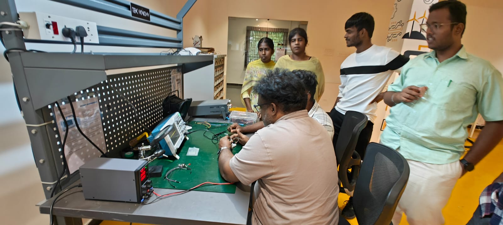
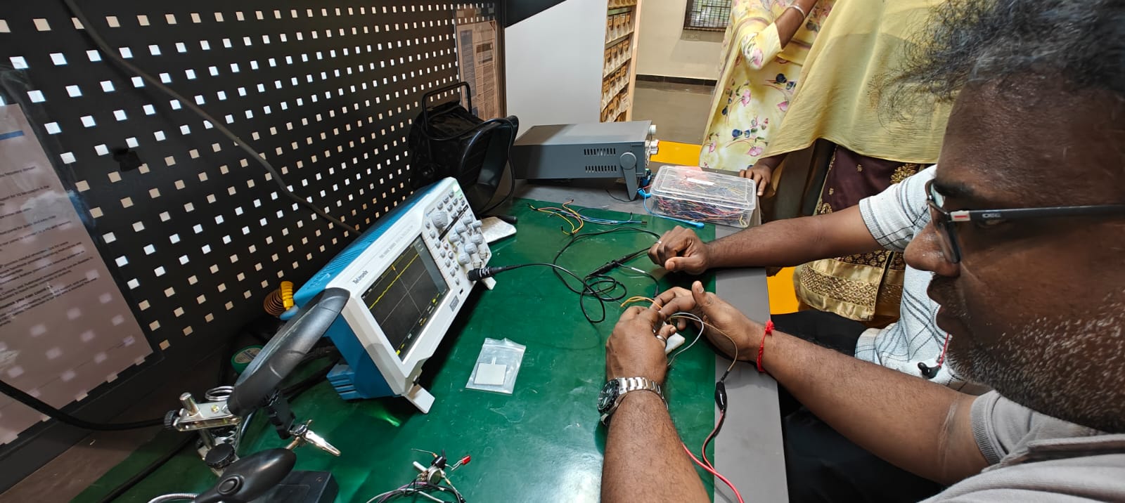
We selected a rotary potentiometer to study its analog signal output. The analog voltage was measured using a digital storage oscilloscope (Tektronix TBS1052C), powered through a DC variable power supply (KPS1505DF).
Name | Contribution Description |
Hariharan M | Led the selection of the input device (rotary potentiometer), connected the circuit, and handled oscilloscope signal interpretation. Documented the observations and structured the assignment content. |
Charath | Helped set up the DC power supply, ensured correct voltage output, and assisted in wiring the potentiometer to the oscilloscope. Took key measurements and helped capture images07. |
Sabarish | Focused on operating the oscilloscope, adjusting channel and scale settings, and interpreting waveform stability. Also helped explain analog signal behavior to the group. |
Thomsan | Took charge of photography and documenting the step-by-step setup. Created labeled reference images07 of both oscilloscope and power supply and managed the tool usage log. |
Equipment Used
1. Rotary Potentiometer (10kΩ)
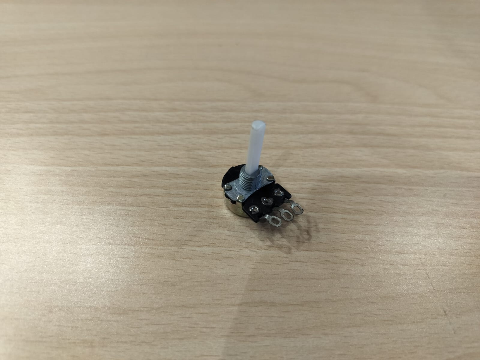
- Acts as a variable resistor
- Outputs continuous analog voltage (0–5V) depending on shaft rotation
2. Oscilloscope – Tektronix TBS1052C
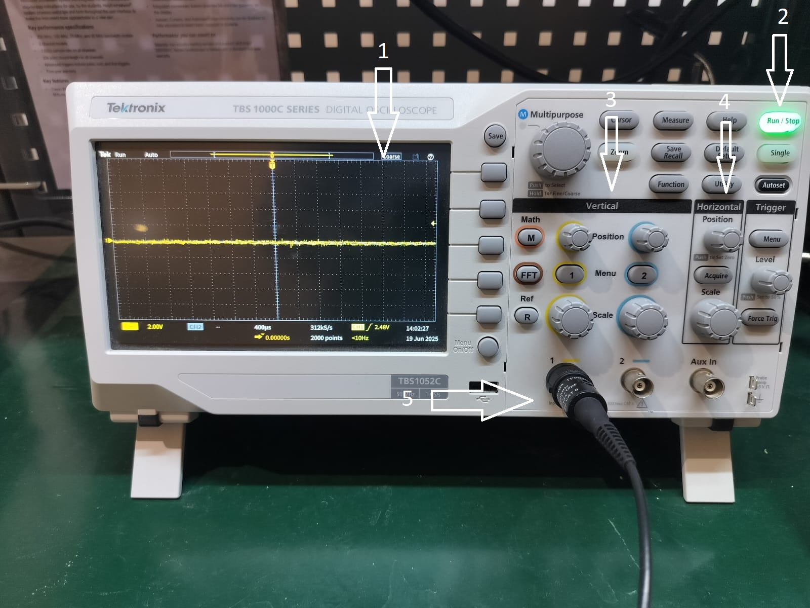
Labeled Features:
- Display – Shows waveform of the probed signal
- Run/Stop Button – Starts/stops signal capture
- Multipurpose Knob – Used for navigating and setting values
- Autoset Button – Automatically adjusts the view
- CH1 Input Probe – Input signal from potentiometer
3. DC Power Supply – KPS1505DF

Labeled Features:
- Display – Shows voltage, current, and power
- Knobs – Adjust current and voltage
- Output Terminals – Banana plug outputs (red = +, black = GND)
- Connected Wires – Supplying 5V to potentiometer
- Power Button – Main switch to turn ON/OFF supply
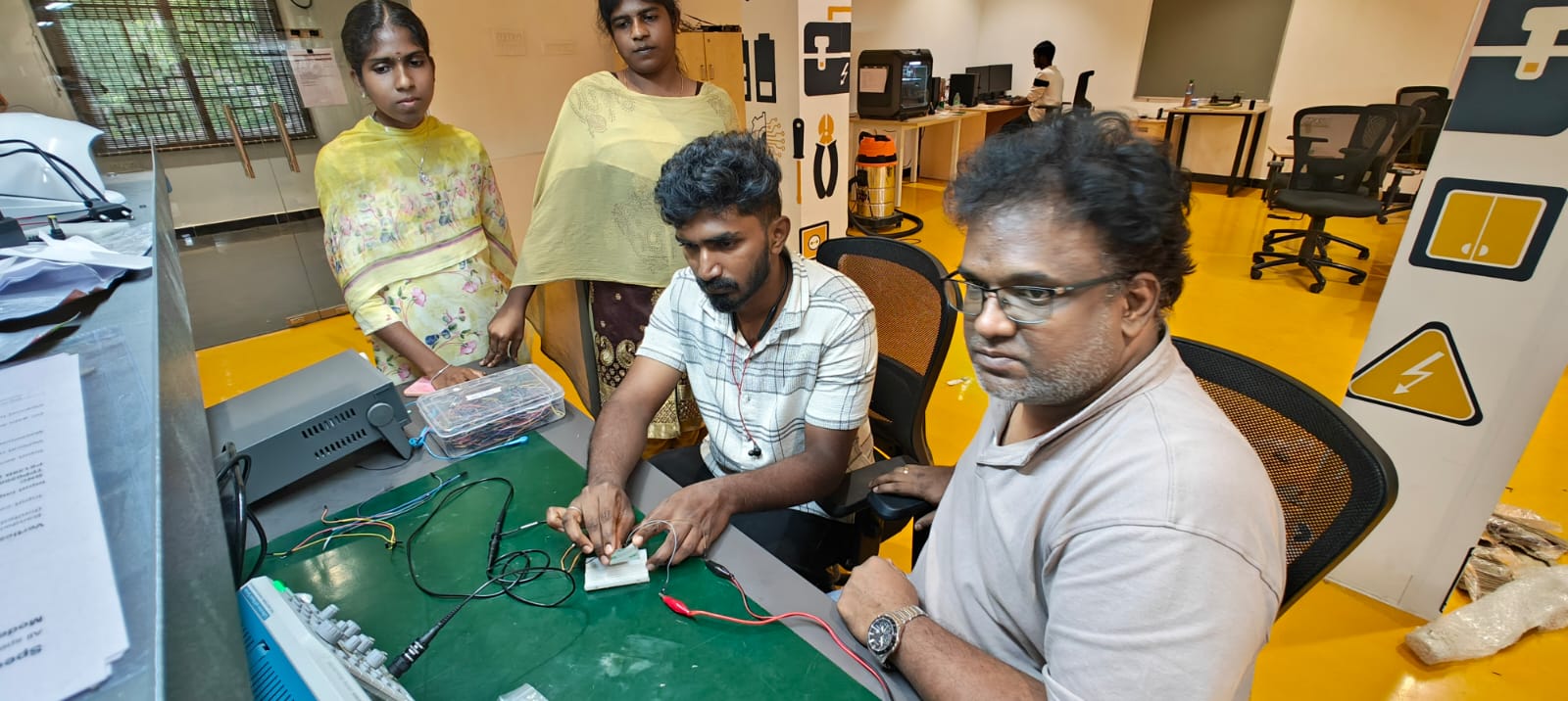
Circuit Setup
- Power Source: 5V from DC power supply
- Connections:
- Potentiometer side pins → 5V and GND
- Center pin (wiper) → Oscilloscope CH1 probe
- Measurement: Rotating the shaft changes output voltage, observed in real-time on oscilloscope
Observations
- Analog Behavior: As we rotated the potentiometer:
- Clockwise → Voltage increased
- Counter-clockwise → Voltage decreased
- Oscilloscope Output: A stable analog voltage line that moves up or down smoothly with rotation.
- No digital transitions (HIGH/LOW), confirming analog-only behavior.
What We Learned
As a group, we learned the following important technical and practical concepts:
Analog vs. Digital Input Devices
We learned the difference between analog devices (like potentiometers that give a range of voltage values) and digital devices (like push buttons or IR sensors that provide discrete HIGH/LOW output).
How to Use an Oscilloscope
We understood how to:
Connect and probe a signal
Adjust voltage and time divisions
Use autoset, trigger, and channel settings
Interpret the analog waveform
Using a DC Power Supply Safely
We learned how to set the desired voltage and current limits, connect the output terminals properly, and power a circuit safely using a bench power supply.
Importance of Signal Visualization
Seeing the live waveform helped us understand the concept of continuous analog signals and how physical movement (rotation of the potentiometer) translates into voltage variation.
Final Out Video
<<< Back to Lab Page