
Week 8
Assignment: Electronics Production
Group assignment
The Link of Group assignments.
Individual assignment
- make and test a microcontroller development board that you designed
- extra credit: make it with another process
Board Selection and Specifications
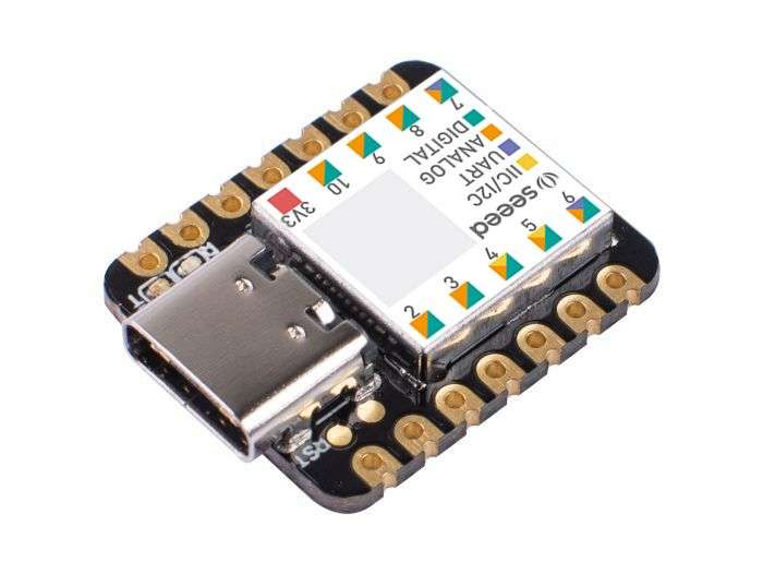
The Seeed Studio XIAO microcontroller board is selected for this project due to its compact size, powerful processing capabilities, and versatile connectivity options. It is based on the SAMD21G18 ARM Cortex-M0+ microcontroller, making it suitable for compact and low-power designs.
- Microcontroller: SAMD21G18 (ARM Cortex-M0+)
- Operating Voltage: 3.3V
- Digital I/O Pins: 11
- Analog Input Pins: 6 (12-bit ADC)
- Communication Protocols: UART, I2C, SPI
- Power Supply: 3.3V and 5V via USB-C
- Programming Interface: USB-C with native USB support
- Onboard LEDs: Power (green) and user-programmable (yellow)
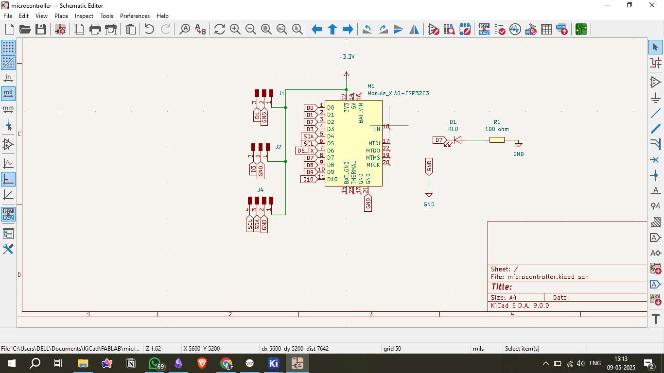
Schematic Design in KiCad
Creating the schematic in KiCad is a critical step in the PCB design process. It involves defining the electrical connections between the various components, including the Seeed XIAO microcontroller and supporting components like resistors, capacitors, and headers.
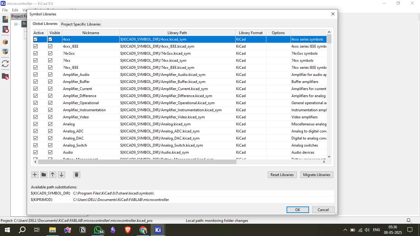
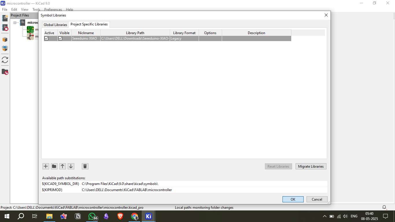
- Library Setup: Import the Seeed XIAO library to ensure accurate component symbols and footprints.
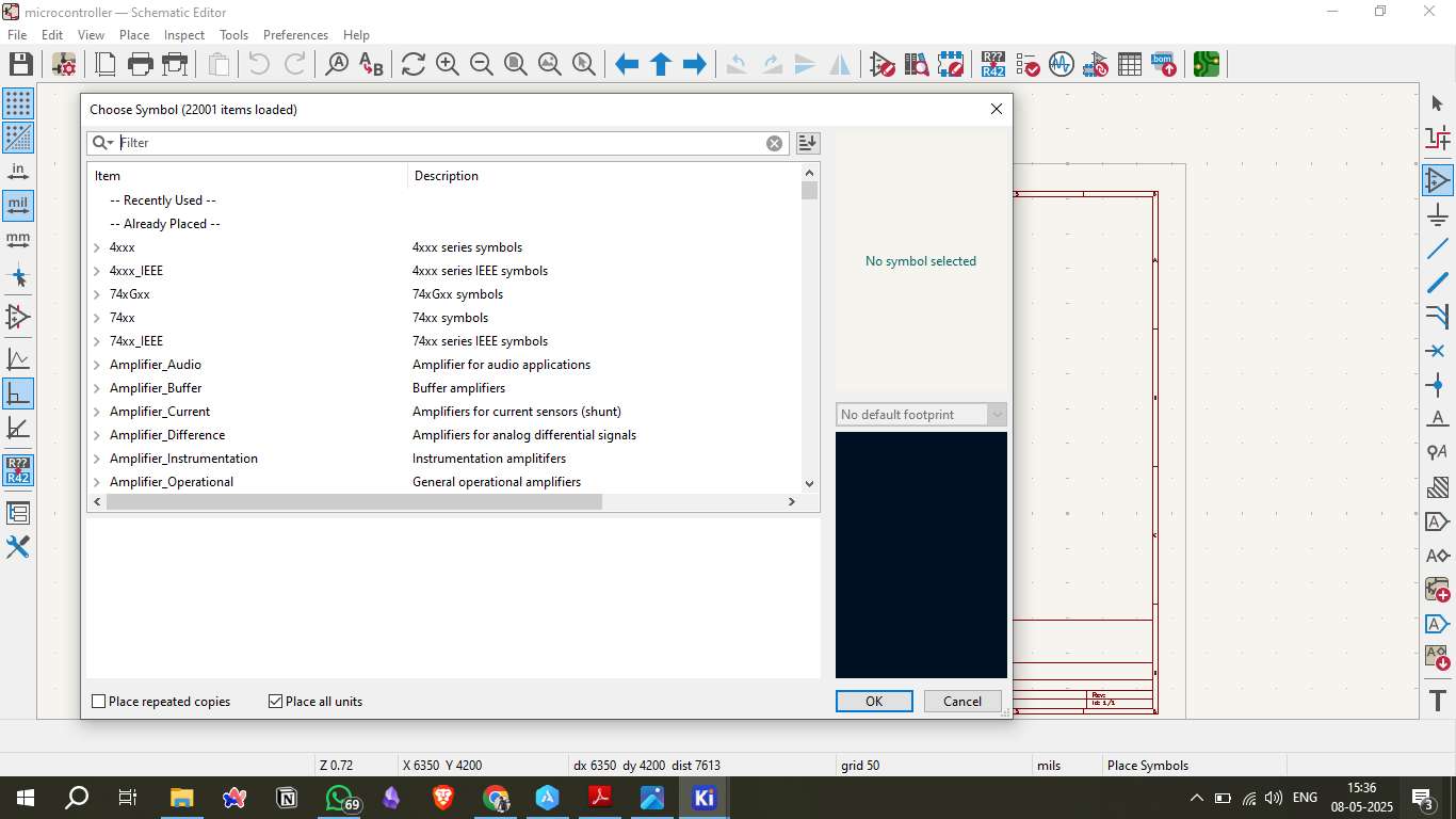
- Component Placement: Add the XIAO symbol along with required passive components like resistors and capacitors.
- Electrical Connections: Connect the components using the 'Wire' tool, ensuring correct power (VCC), ground (GND), and signal routing.
- Electrical Rule Check (ERC): Run the ERC to verify the correctness of the schematic, checking for unconnected pins and mismatched connections.
- Annotate and Label: Properly label all components to maintain clarity in the design.
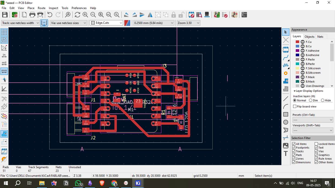
PCB Layout
Once the schematic is complete, the next step is to arrange the physical components on the PCB layout. This process ensures that the electrical connections are correctly translated into a physical design.
- Define Board Outline: Set the PCB boundaries, ensuring the board size fits within the constraints of the milling machine.
- Routing the Traces: Use the 'Route Tracks' tool to connect the components according to the schematic.
- Add Ground Plane: Add a copper pour for the ground plane to reduce electrical noise and improve signal stability.
- Design Rule Check (DRC): Run the DRC to verify that the layout adheres to the defined design rules.
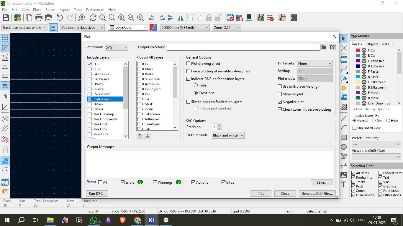
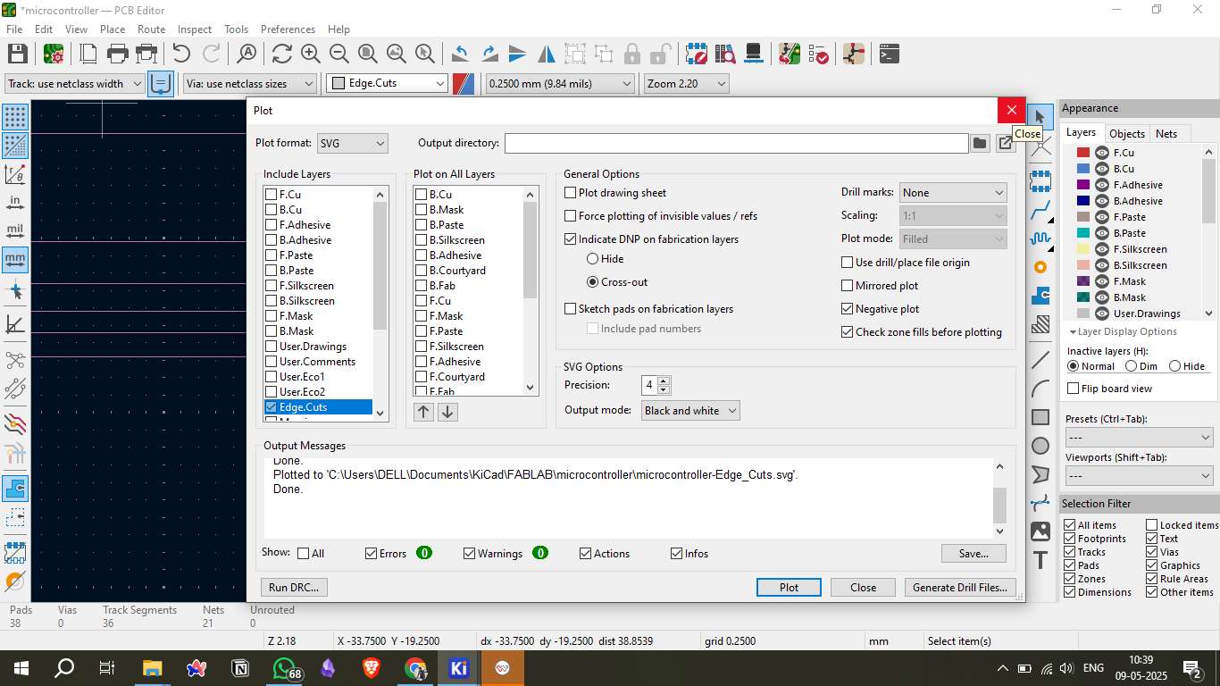
Generate SVG Files
After completing the PCB layout, the next critical step is generating the SVG files required for manufacturing. These files contain the precise design information needed for the milling machine to create the physical board.
- Layer Selection: Choose the appropriate layers for top copper, bottom copper (if double-sided), and edge cuts.
- SVG File Export: Use the 'Plot' option in KiCad's PCB editor to export the SVG files.
- Scale and Line Width Settings: Adjust the scale to 1:1 and set the line width appropriately to ensure precise cuts during milling.
- File Verification: Use an SVG viewer to inspect the exported files for accuracy.
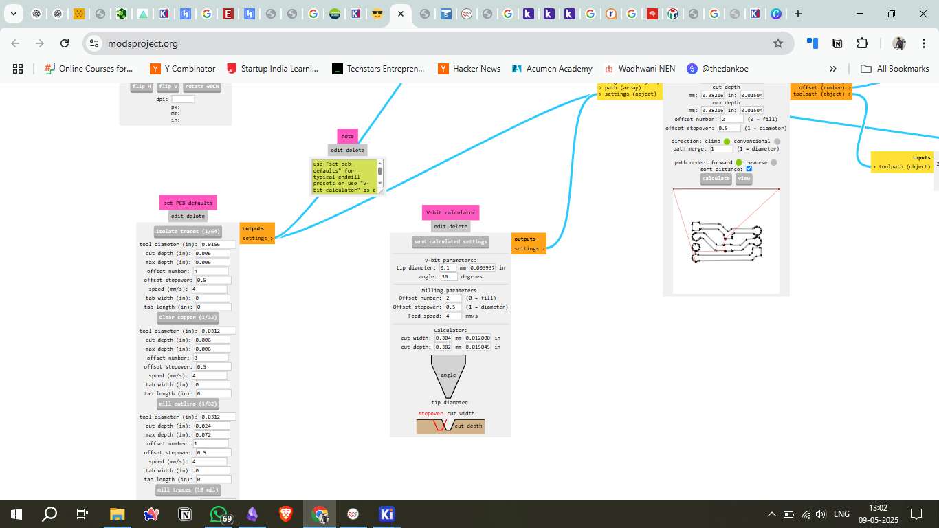
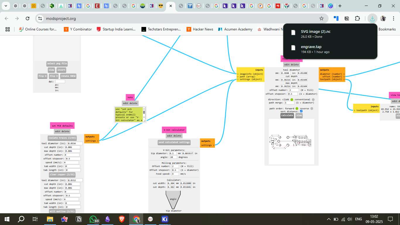
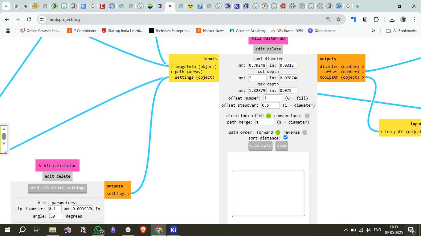
Convert to G-Code (Mods CE)
Converting the SVG files to G-Code is an essential step for controlling the milling machine. Mods CE is a popular choice for this purpose, as it provides precise control over tool paths and cutting parameters.
- Open Mods CE: Launch the Mods CE web application.
- Import SVG File: Load the SVG file generated from KiCad.
- Set Milling Parameters: Configure the cutting parameters, including spindle speed, cut depth, and feed rate.
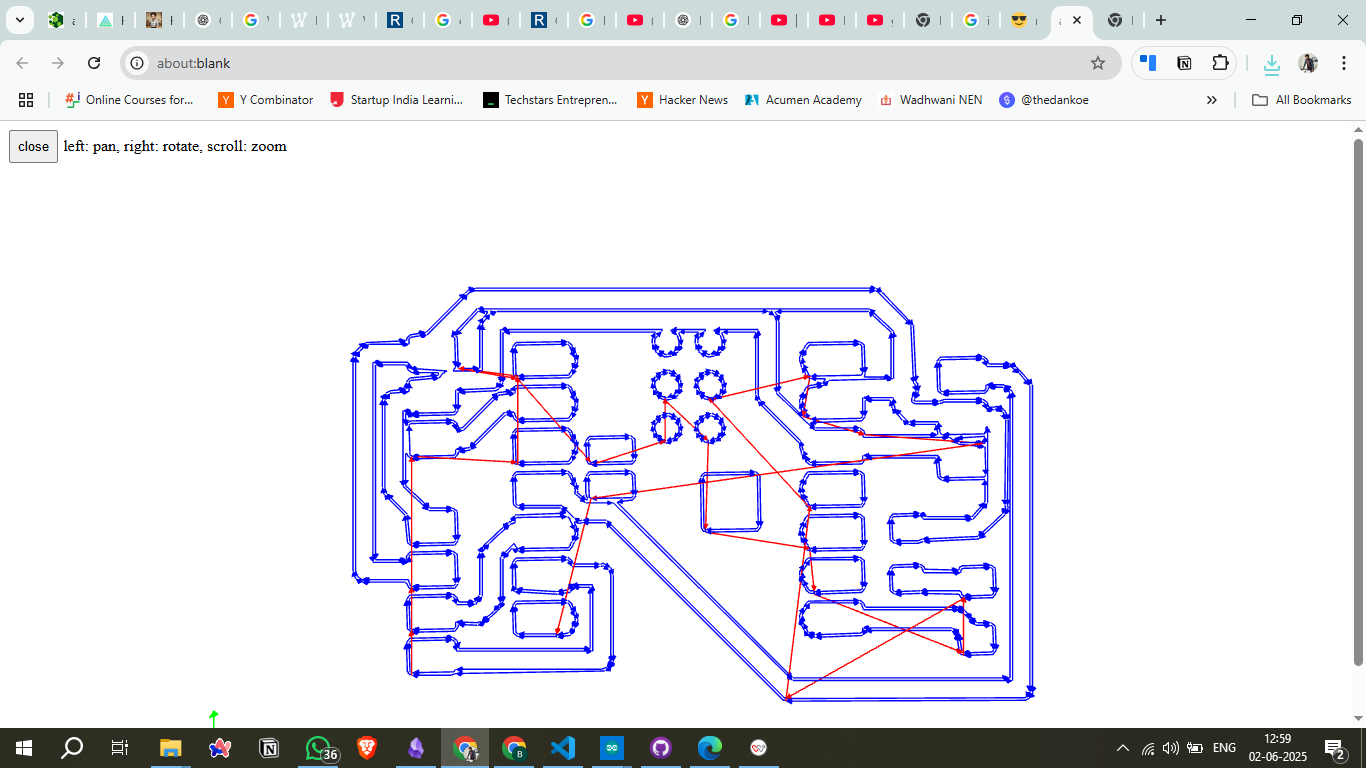
- Generate G-Code: Use the 'Calculate' button to generate the G-Code.
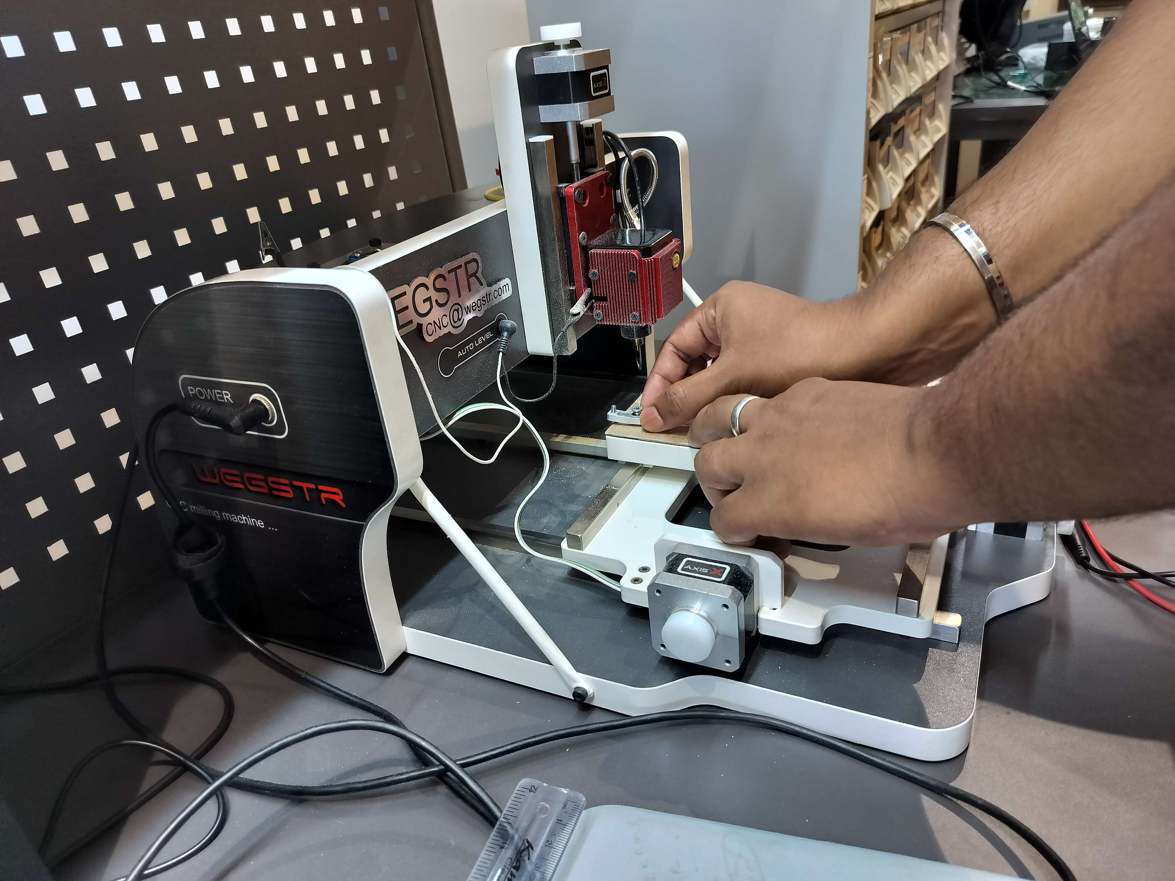
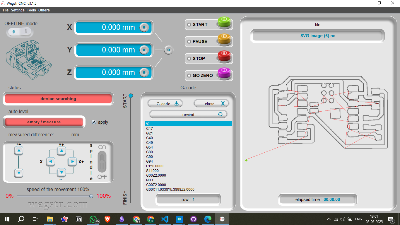
WEGSTR 3-Axis Desktop PCB CNC
The WEGSTR 3-Axis Desktop CNC is a compact, precise, and user-friendly milling machine specially designed for PCB (Printed Circuit Board) prototyping and lightweight CNC operations. It is ideal for makers, students, and electronics labs to fabricate high-quality custom PCBs in-house without relying on external fabrication services.
Key Features
- 3-Axis Machining: Allows precise control over the X, Y, and Z axes for detailed milling.
- High Precision: Suitable for fine-trace PCB layouts and small components.
- Desktop Size: Space-saving design that fits easily on a desk or lab bench.

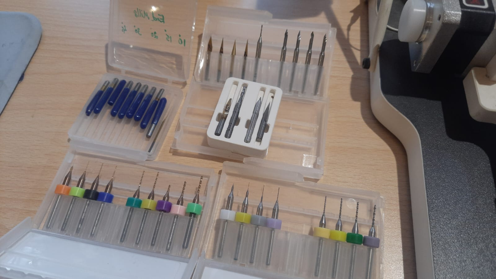
Milling Bits:
1/64" (0.4mm) flat end mill for milling traces
1/32" (0.8mm) flat end mill for outline cutting
Mounting Tool: Double-sided tape
Cleaning Tools: Brush, vacuum cleaner
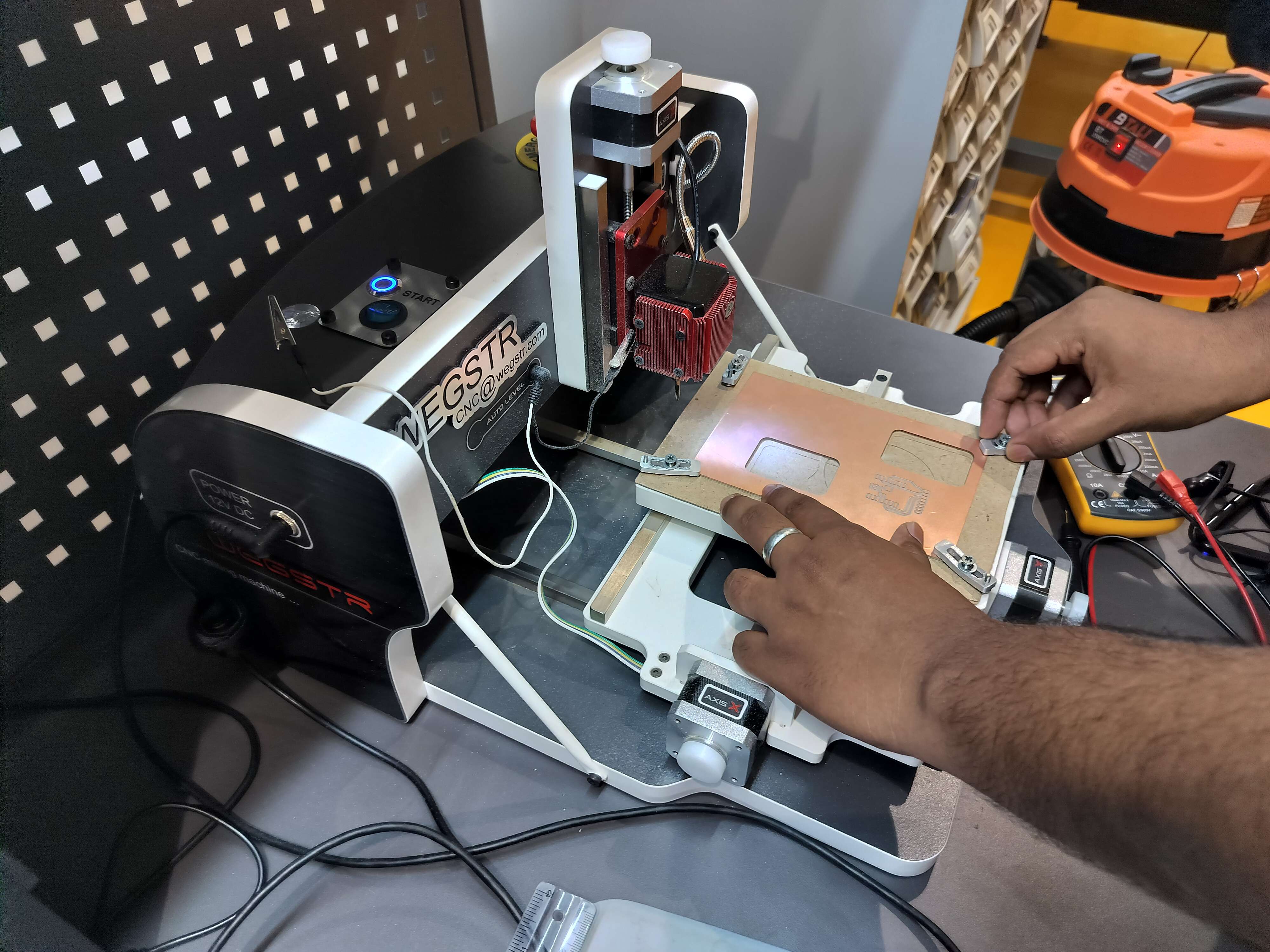
Setup Milling Machine and Prepare Copper Plate
Properly setting up the milling machine and preparing the copper plate is critical for accurate PCB production.
- Secure the Copper Plate: Mount the copper-clad board securely on the milling bed.
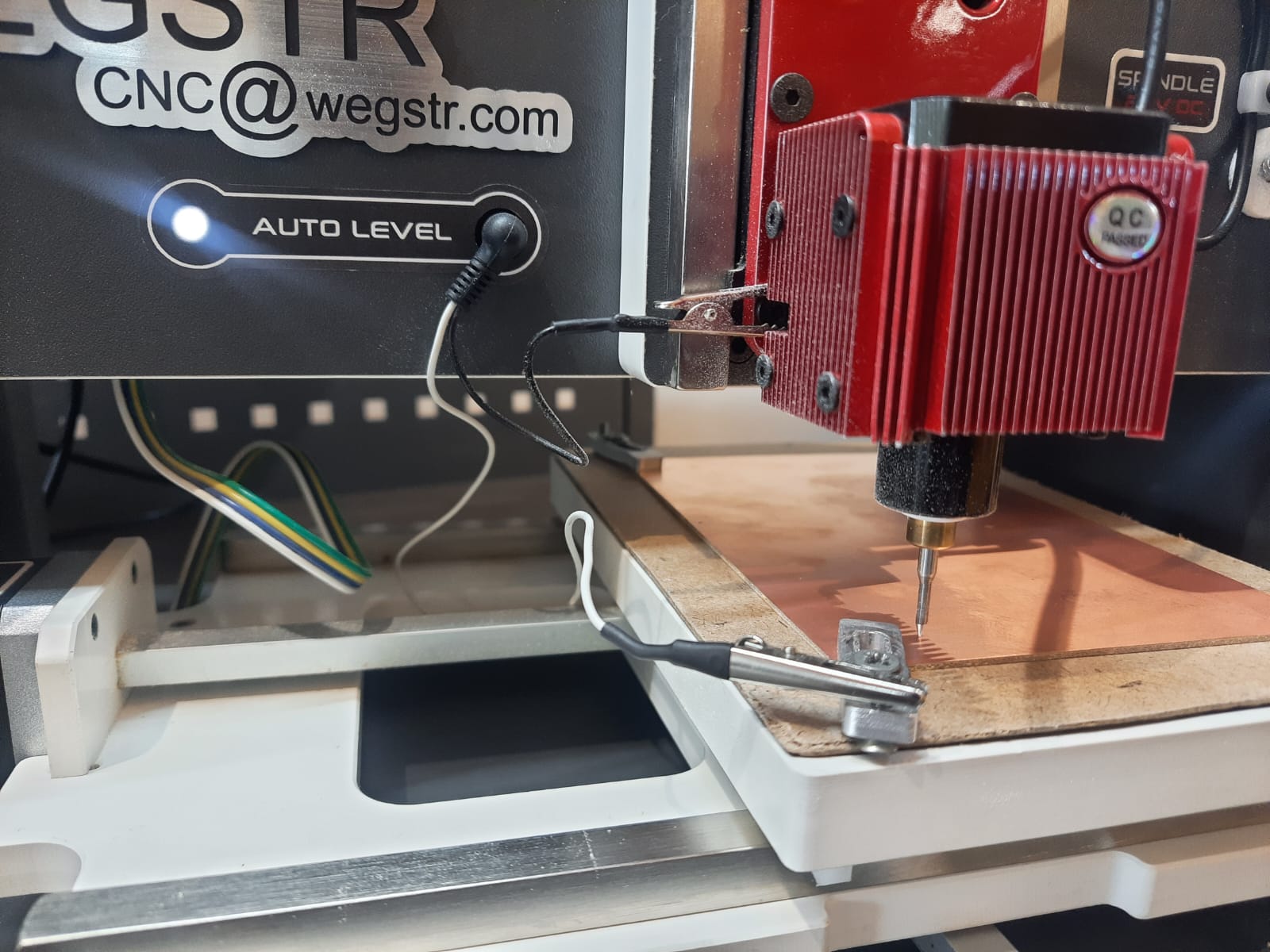
- Set Zero Points: Calibrate the X, Y, and Z zero points for accurate cutting.
- Verify Bed Leveling: Ensure the milling bed is level to avoid uneven cuts.
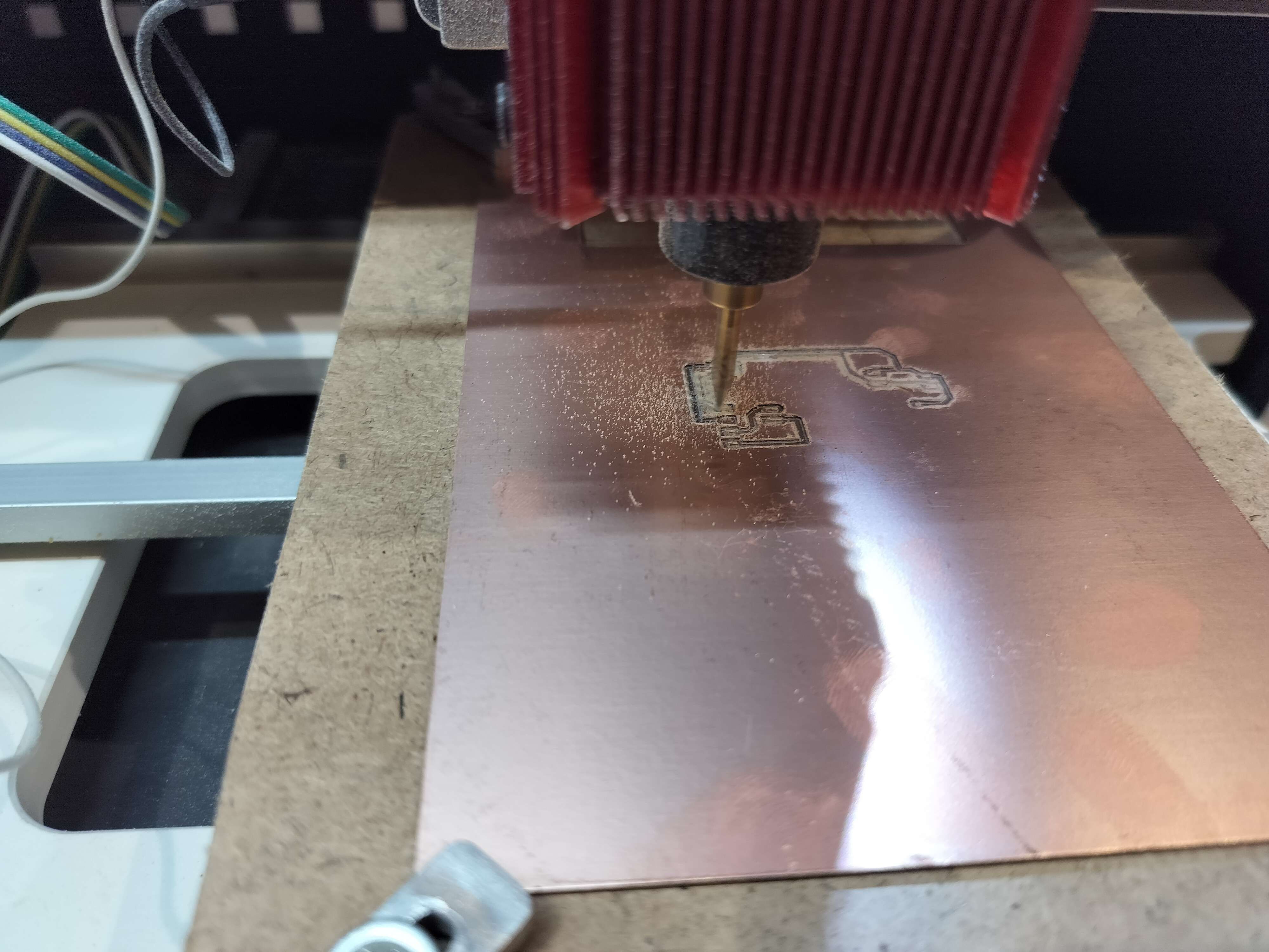
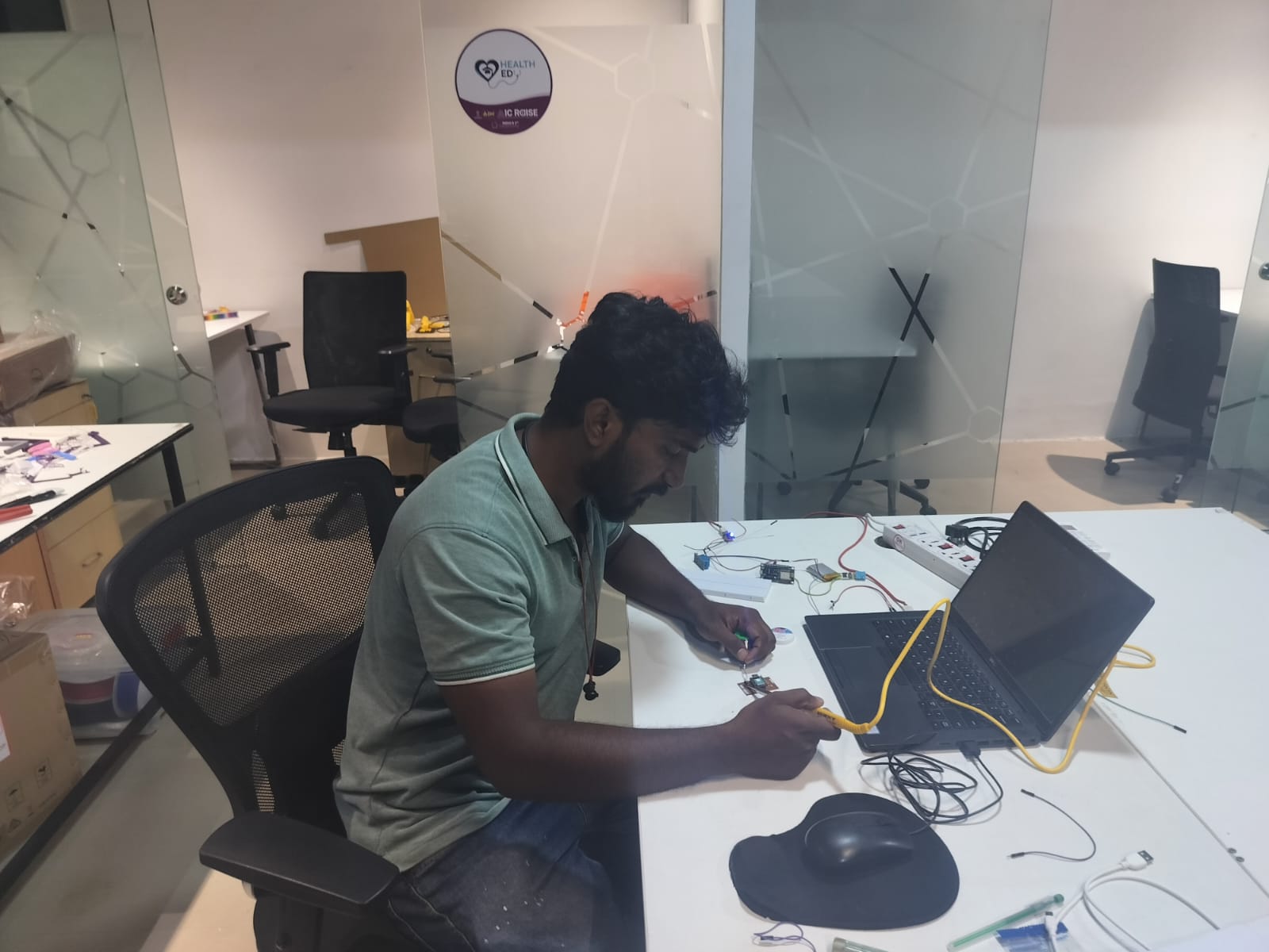
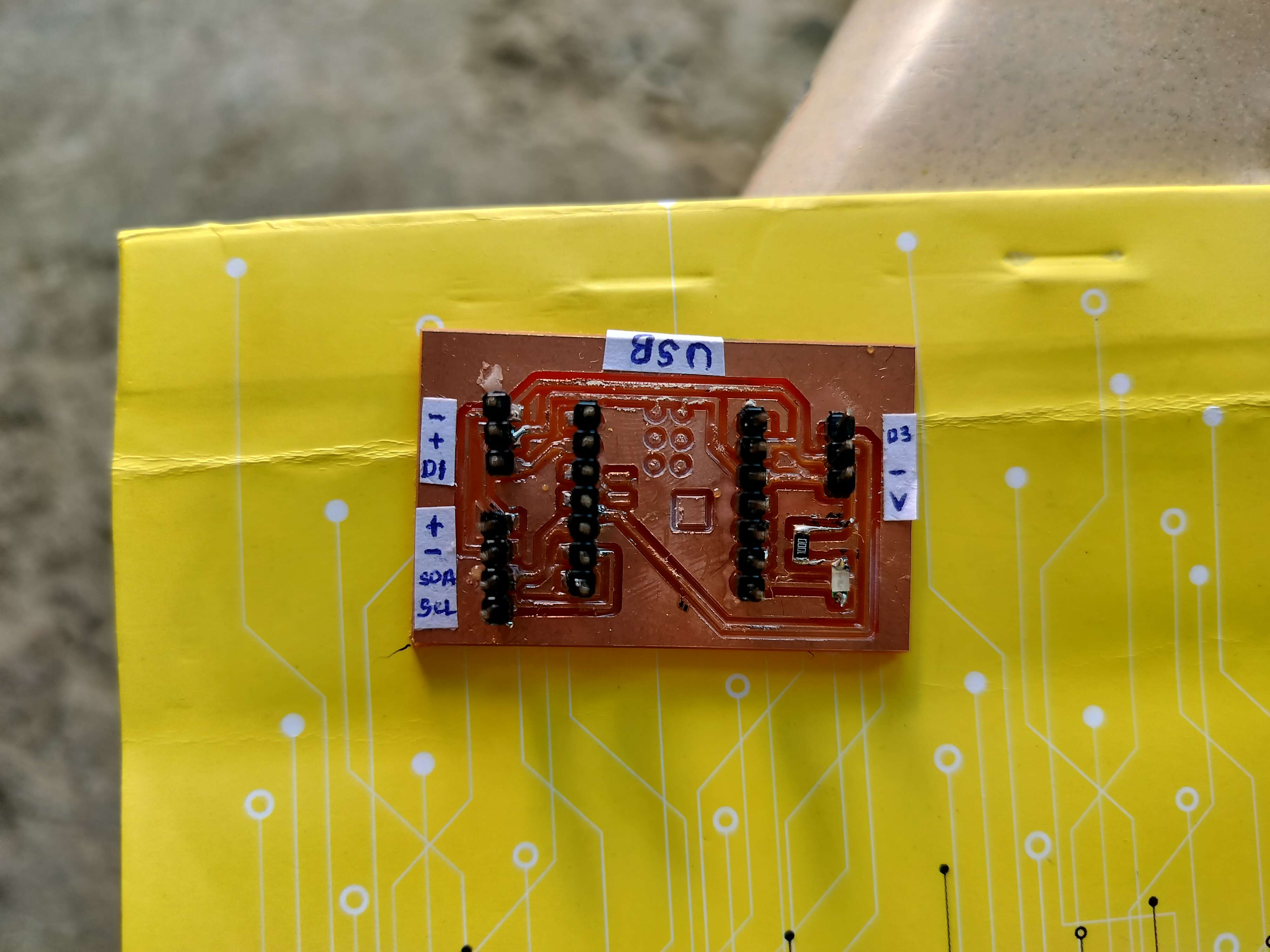
Solder Components
Milling the PCB and soldering components are the final stages of board production before testing. This step ensures the physical connections match the designed circuit and that the board is fully functional.
- Secure the Copper Plate: Mount the copper-clad board onto the milling machine bed.
- Start Milling: Begin the milling process, carefully monitoring for issues like copper lift or broken traces.
- Inspect the Milled Board: Check for clean, isolated traces without short circuits.
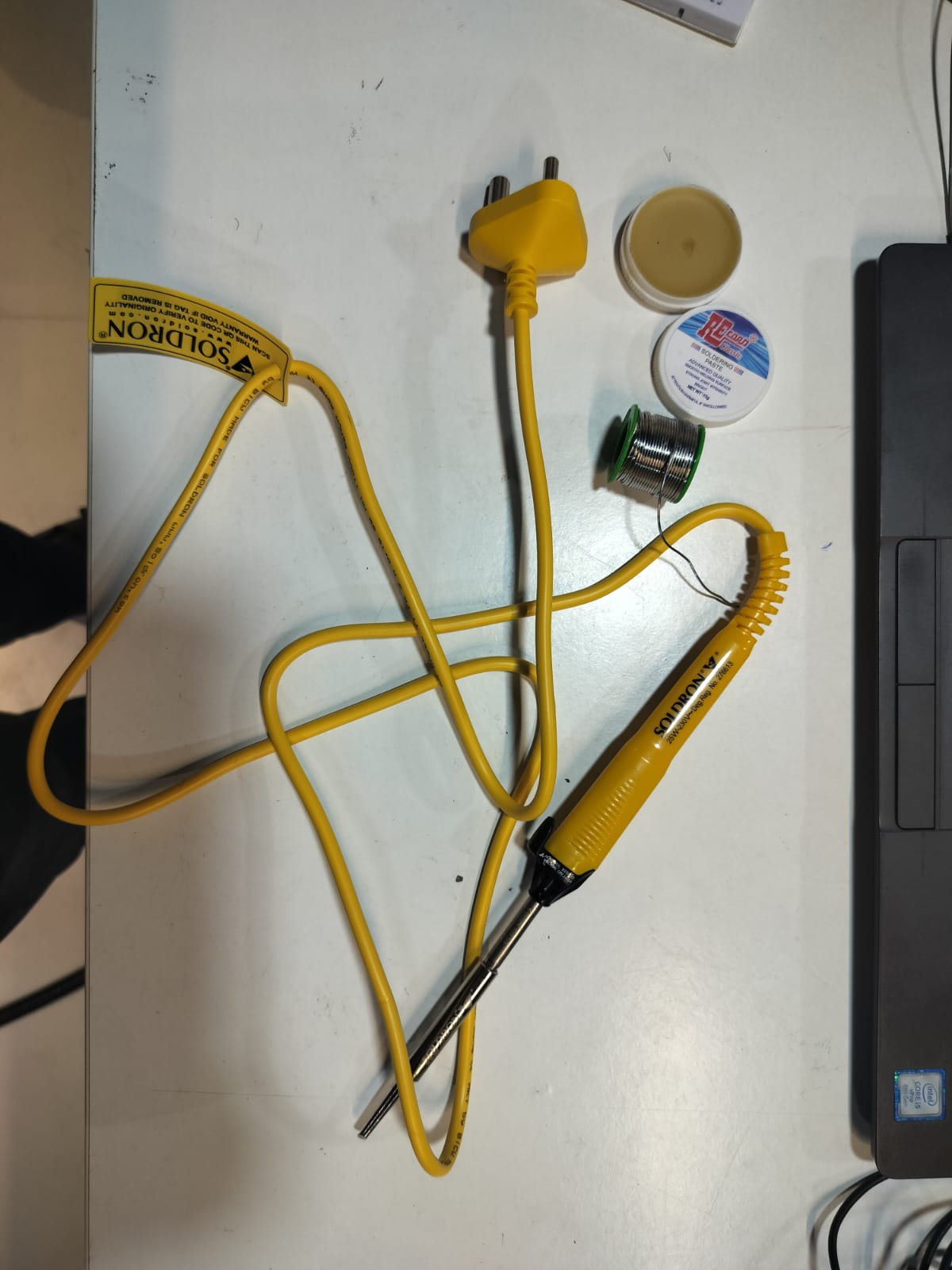
- Solder the Components: Carefully solder the Seeed XIAO board, resistors, capacitors, and connectors.
Using a soldering iron (Soldron 25W) to connect circuit components.
- Soldering iron
- Lead-based solder wire
- Flux paste for better conductivity
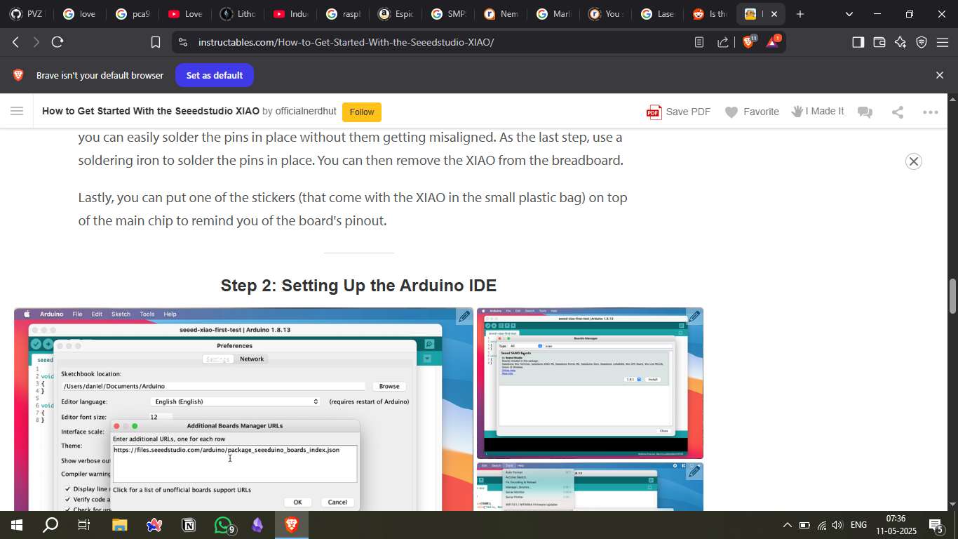
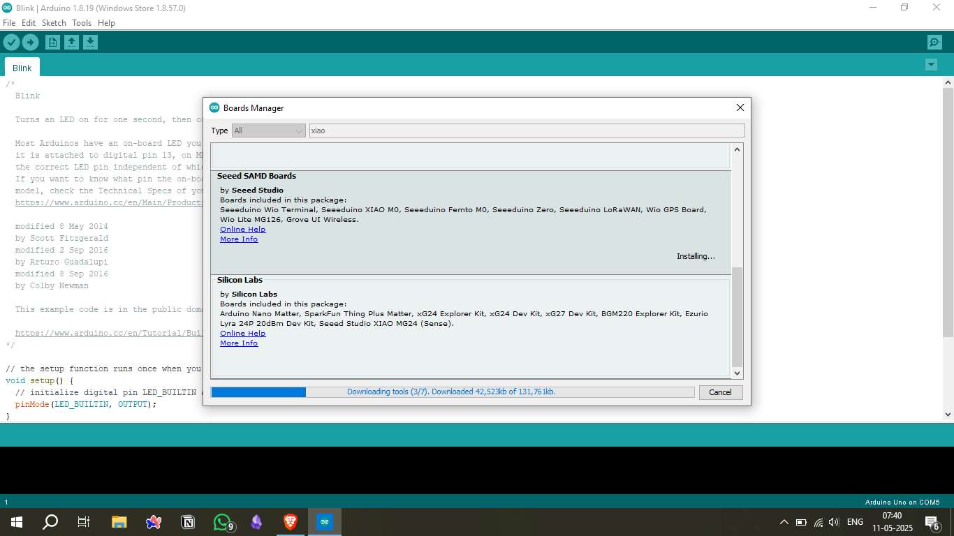
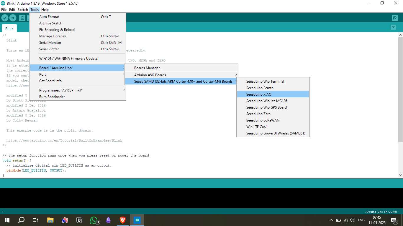
Install Required Libraries
To fully utilize the Seeed XIAO board, you will need to install the required libraries for the sensors and modules used in your project. This ensures smooth communication and proper functionality.
- Open the Library Manager: In the Arduino IDE, go to Sketch -> Include Library -> Manage Libraries.
- Search for Required Libraries: Use the search bar to find libraries specific to your components.
- Install the Libraries: Click Install to add the required libraries to your IDE.
- Verify Installation: Run a simple test sketch to confirm the libraries are correctly recognized.
Source Code Example
void setup() {
          pinMode(0, OUTPUT); // Connect LED to D0
        }

        void loop() {
          digitalWrite(0, HIGH);
          delay(500);
          digitalWrite(0, LOW);
          delay(500);
}Upload Source Code and Final Board Photo
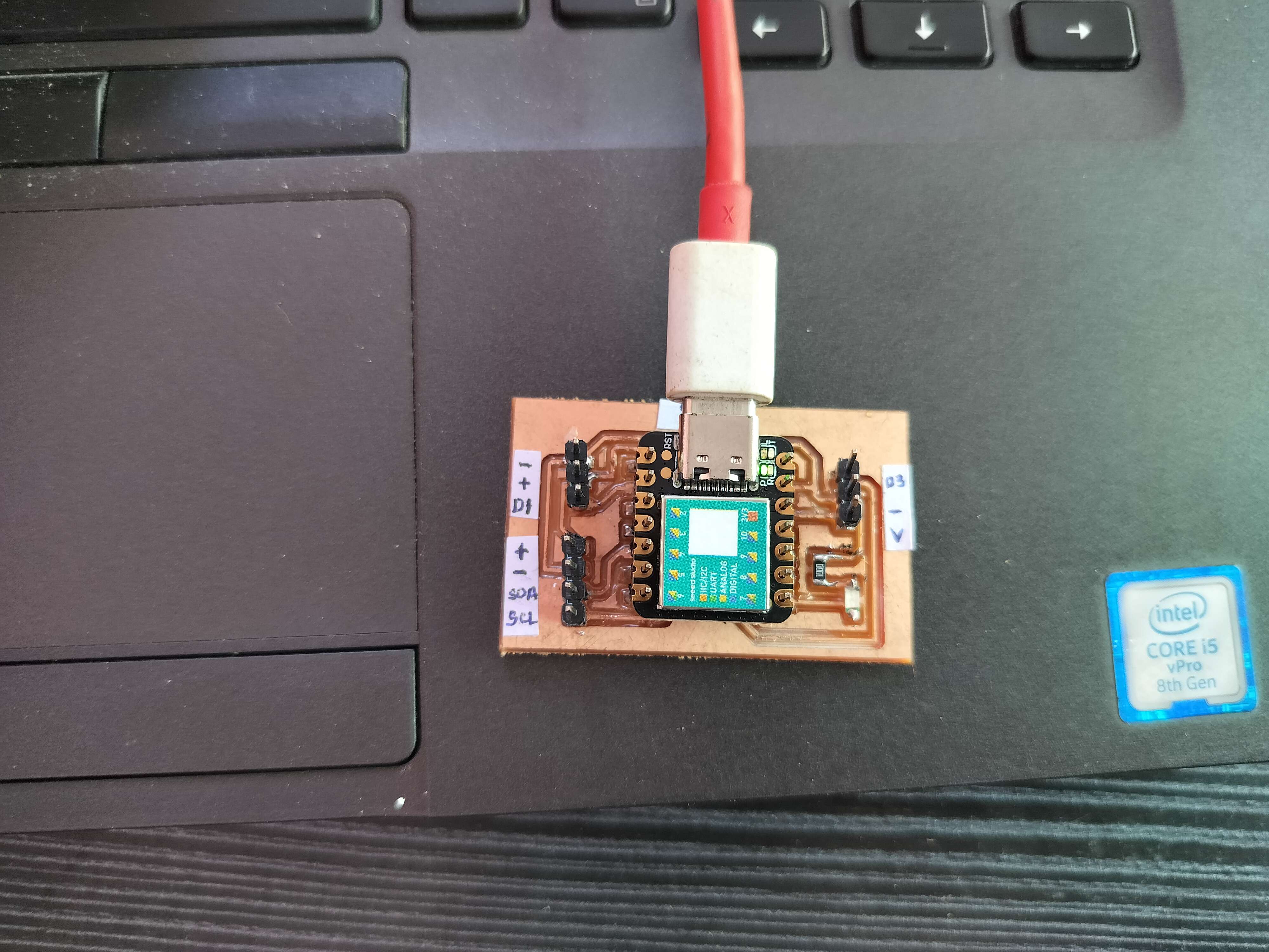
Uploading the final source code and a high-quality photo of the completed board is essential to demonstrate the functionality and design quality.
- Prepare the Source Code: Ensure your final code is clean, well-documented, and free from errors.
- Test the Final Code: Run a final test to confirm that the code works as intended.

Hero Shot
Downloadable Files
Tools & Platforms Used
Mods CE: SVG to G-code conversion - https://modsproject.org/
KiCad: Schematic and PCB design - https://kicad.org/
Arduino IDE: Microcontroller programming - https://arduino.cc
Seeeduino XIAO Docs: Board reference - XIAO Wiki
Table of Contents
- Board Selection and Specifications
- Schematic Design in KiCad
- PCB Layout
- Generate SVG Files
- Convert to G-Code (Mods CE)
- Setup Milling Machine and Prepare Copper Plate
- Solder Components
- Install Required Libraries
- Upload Source Code and Final Board Photo
- Hero Shot
- Downloadable Files
- Tools & Platforms Used