
Week 4
Theme: Embedded Programming
Group assignment
The Link of Group assignments.
Individual assignment
- browse through the data sheet for your microcontroller write a program for a microcontroller, and simulate its operation, to interact (with local input &/or output devices) and communicate (with remote wired or wireless connections)
- extra credit: test it on a development board
- extra credit: try different languages &/or development environments
What is Embedded Programming
An embedded system is a small or large non-computer device with integrated software based on microcontrollers and microprocessors for performing a special function or a limited set of functions. It may or may not have a screen and a keyboard, be either programmable or non-programmable, perform a single function in isolation or work as a part of a large system.
Common Features of Embedded Systems
There are many features that embedded systems may exhibit, but there are several that are common across all devices. These include:
- Designed to perform specific repeated functions on certain single-purpose devices
- Should perform their functions deterministically, within a prescribed timeframe
- Based on microprocessors and microcontrollers
- Work with limited memory, power and computing resources
- Strong performance — since software is written for handling a single task on a certain device, its performance is usually close to perfect, which is crucial for end-users
- Low power consumption — most devices require little power for operations, which means that they can be applied in various locations and work in complicated circumstances; it also means resource usage optimization
How it works
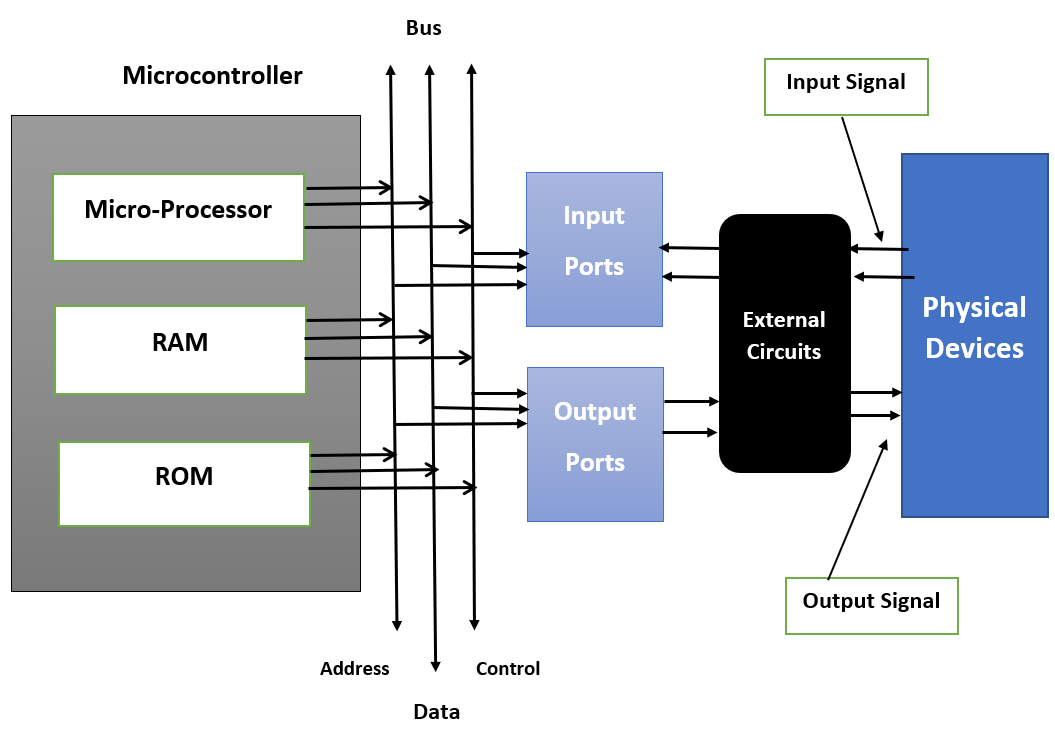
Embedded systems operate from the combination of hardware and software that focuses on certain operations. An embedded system at its heart has microcontroller or microprocessor hardware on which user writes the code in form of software for control of the system. Here is how it generally works:
- Hardware Layer: Some of the hardware elements that are incorporated in an embedded system include the sensor, actuator, memory, current I/O interfaces as well as power supply. These components are interfaced with the micro controller or micro processor depending up on the input signals accepted.
- Input/output (I/O) Interfaces: They to give the system input in form of data from sensors or inputs made by the users and the microcontroller processes the data received. The processed data is then utilized to coordinate the output devices such as displays, motors or communication modules.
- Firmware: which is integrated within a system's hardware comprises of certain instructions to accomplish a task. Such software is often used for real time processing and is tuned to work in the most optimal manner on the system hardware.
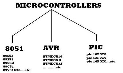
Basics of Microcontrollers Types
Any electric appliance used to store, measure & display the information otherwise measures comprise of a chip in it. The microcontroller's basic structure includes different components.
- CPU: The microcontroller is called a CPU device, used to carry & decode the data & finally completes the allocated task effectively. By using a central processing unit, all the microcontroller components are connected to a particular system. Instruction fetched through the programmable memory can be decoded through the CPU.
- Memory: In a microcontroller, the memory chip works like a microprocessor because it stores all the data as well as programs. Microcontrollers are designed with some amount of RAM/ROM/flash memory to store the program source code.
- I/O Ports: Basically, these ports are used to interface otherwise drive different appliances like LEDs, LCDs, printers, etc.
- Serial Ports: Serial ports are used to provide serial interfaces between microcontroller as well as a variety of other peripherals like parallel port.
- Timers: A microcontroller includes timers otherwise counters. These are used to manage all the operations of timing and counting in a microcontroller. The main function of the counter is to count outside pulses whereas the operations which are performed through timers are clock functions, pulse generations, modulations, measuring frequency, making oscillations, etc.
- ADC (Analog to Digital Converter): ADC is the acronym of analog to digital converter. The main function of ADC is to change the signals from analog to digital. For ADC, the required input signals are analog and the production of a digital signal is used in different digital applications like measurement devices.
- DAC (Digital to Analog Converter): The acronym of DAC is digital to analog converter, used to perform reverse functions to ADC. Generally, this device is used to manage analog devices such as DC motors, etc.
- Interpret Control: This controller is employed to give delayed control to a running program & interpretation is either internal otherwise external.
- Special Functioning Block: Some special microcontrollers designed for special devices like robots, space systems include a special function block. This block has extra ports to carry out some particular operations.
Datasheet
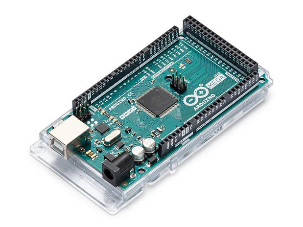
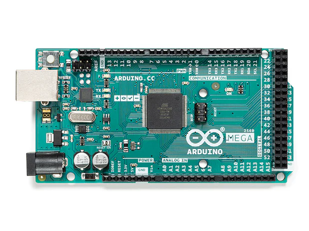
Summary of Arduino Mega: The Arduino Mega 2560 Rev3 is designed for complex applications requiring numerous I/O pins and high processing power. Compared to the Arduino UNO, it offers more input/output capability in the same form factor. It is ideal for robotics, 3D printing, and wireless applications when paired with compatible shields.
Technical Specification
- Operating Voltage: 5V
- Input Voltage (recommended): 7–12V
- Digital I/O Pins: 54
- PWM Channels: 15
- Analog Input Pins: 16
- DC Current per I/O Pin: 20 mA
- Clock Speed: 16 MHz
- Operating Temperature: -40°C to 85°C
Microcontroller Details
Main MCU: ATmega2560 running at 16 MHz, with 256 KB Flash (8 KB used by bootloader), 8 KB SRAM, and 4 KB EEPROM.
USB-to-Serial Converter: ATmega16U2 with 16 KB ISP Flash, 512 B EEPROM, and 512 B SRAM.
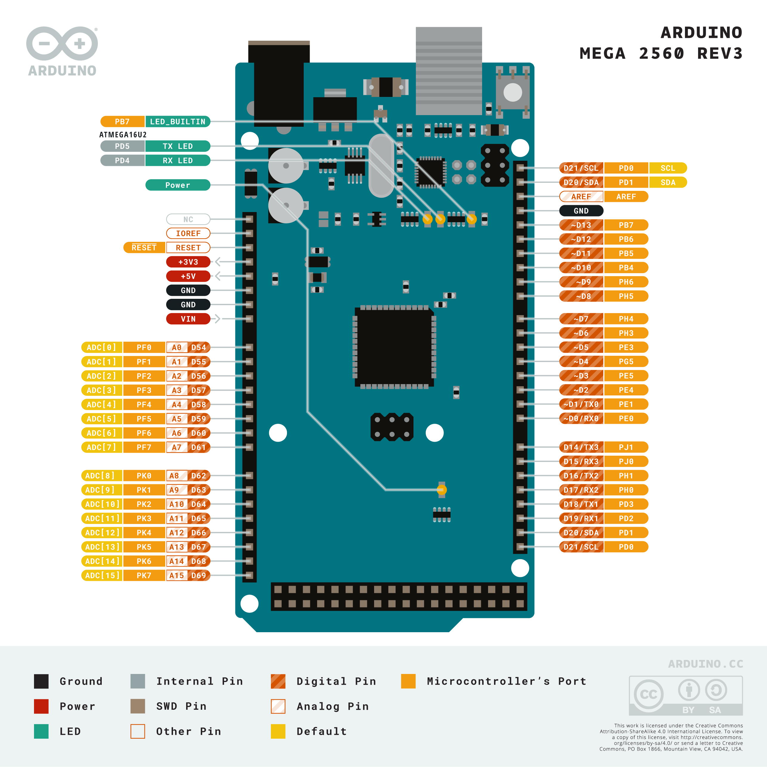
Pinout Overview
The board features 54 digital I/O pins (of which 15 support PWM), 16 analog inputs, power pins, communication pins, and specialized functions such as external interrupts and I2C/SPI interfaces.
Digital I/O
Digital Pins D0–D53: General purpose digital pins, some with additional functions such as UART (D0/D1), PWM outputs, and communication interfaces like SPI and I2C.
Analog Input
Analog Pins A0–A15: Can be used as analog inputs or digital I/O. These are capable of reading analog signals and converting them to digital values (10-bit resolution).
Power Pins
- IOREF: Reference voltage for digital logic
- 3.3V: Output of onboard 3.3V regulator
- 5V: Main 5V power rail
- GND: Ground pins
- VIN: Input voltage from external power source
PWM Pins
PWM capable pins: 2–13 and 44–46. These support analogWrite() for controlling motor speed, LEDs, etc.
Serial Communication (UART)
The board has 4 hardware UARTs: Serial0 (D0/D1), Serial1 (D19/D18), Serial2 (D17/D16), Serial3 (D15/D14).
SPI Communication
SPI Pins: 50 (MISO), 51 (MOSI), 52 (SCK), and 53 (SS). Used for high-speed communication with SPI-compatible devices.
I2C Communication
I2C Pins: 20 (SDA) and 21 (SCL). Used for communication with I2C-compatible devices such as sensors and displays.
Memory Details – Flash, SRAM, EEPROM
- Flash: 256 KB (8 KB used by bootloader)
- SRAM: 8 KB
- EEPROM: 4 KB
Bootloader and Programming Methods
The board is preloaded with a bootloader that allows programming via the USB port using the Arduino IDE. It can also be programmed using ICSP headers and an external programmer.
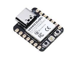
Seeed XIAO ESP32C3
Summary of XIAO ESP32C3: The Seeed Studio XIAO ESP32C3 is a low-power, small-sized microcontroller with integrated Wi-Fi and Bluetooth 5.0 LE. It is suitable for IoT applications and wearable devices due to its compact size, rich peripherals, and secure features. It's built on the RISC-V architecture, providing cost-efficiency and performance.
Technical Specification
- Processor: 32-bit single-core RISC-V (up to 160 MHz)
- Wireless Connectivity: Wi-Fi 802.11 b/g/n (2.4 GHz), Bluetooth 5.0 LE
- Operating Voltage: 3.3 V
- Input Voltage (USB powered): 5 V
- Digital I/O Pins: 11
- PWM Channels: Up to 11
- ADC Channels: 6 (12-bit)
- Interface Support: UART, I2C, SPI, ADC, PWM
- Operating Temperature: -40°C to 85°C
Microcontroller Details
- Chip: ESP32-C3
- Core: 32-bit RISC-V single-core, up to 160 MHz
- Memory: 400 KB SRAM, 4 MB Flash
- Security: AES-128/256, RSA-3072, SHA-2, HMAC, Secure Boot, Flash Encryption
- USB Support: USB 2.0 full speed
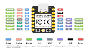
Pinout Overview
The XIAO ESP32C3 board offers 11 Digital I/O pins, 1 UART, 1 I2C, 1 SPI, 1 ADC, and PWM multiplexed pins, dedicated power, reset, and boot pins, and USB-C connector for programming and power.
Digital I/O Pins
GPIO0–GPIO10: Configurable as digital input/output. Most GPIOs are multiplexed with SPI, I2C, UART, ADC, and PWM.
Analog Input Pins
ADC Channels: GPIO0, GPIO1, GPIO2, GPIO3, GPIO4, GPIO5 with 12-bit resolution for analog signal measurement.
Power Pins
- 3V3: Output from LDO regulator
- GND: Ground
- 5V (USB): Power input through USB-C
PWM Pins
All GPIOs (up to 11) support PWM. Useful for motor control, LED dimming, etc.
Serial Communication (UART)
UART Pins: Default TX (GPIO21), RX (GPIO20). Used for programming, serial communication via USB or headers.
SPI Communication
SPI Pins: GPIO6 (MOSI), GPIO7 (MISO), GPIO8 (SCK). Supports master/slave SPI communication with sensors and displays.
I2C Communication
I2C Pins: GPIO4 (SDA), GPIO5 (SCL). Used for connecting multiple sensors and I2C devices.
Memory Details – Flash, SRAM, EEPROM
- SRAM: 400 KB
- Flash: 4 MB
- EEPROM: Not native, can be emulated in Flash
Bootloader and Programming Methods
Bootloader: Preloaded with UF2 bootloader for drag-and-drop programming (Arduino compatible). Programming Interfaces: USB-C (via CDC-ACM), or UART. Supports Arduino IDE and PlatformIO.
Arduino Coding
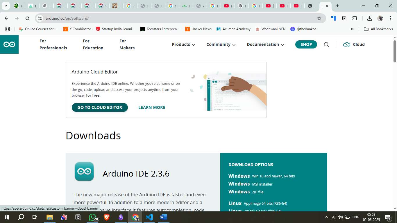
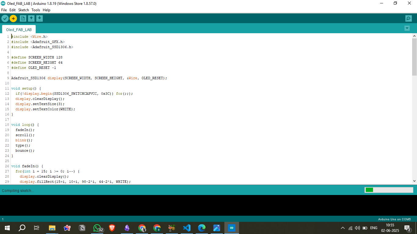
The Arduino Integrated Development Environment (IDE) 1.x is a user-friendly platform designed for writing, compiling, and uploading code to Arduino boards. It offers a straightforward interface suitable for beginners and experienced developers alike.
Learn more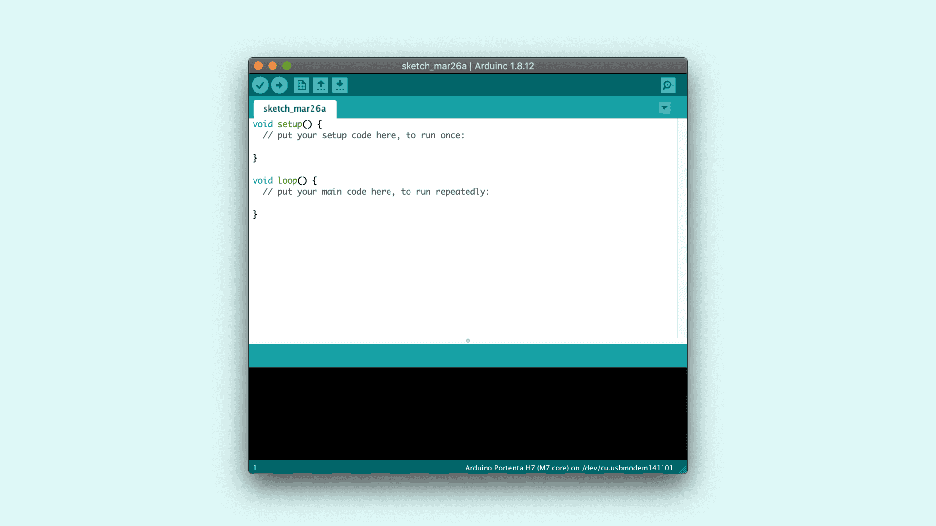
Key Components of the IDE Interface
- Text Editor: The central area where you write and edit your Arduino sketches (programs).
- Message Area: Located below the editor, this section displays feedback messages, including errors and other information during code compilation and uploading.
- Text Console: Provides detailed output messages from the compiler and other tools, aiding in debugging.
- Toolbar: Contains buttons for common actions:
- Verify: Checks your code for errors without uploading it.
- Upload: Compiles and uploads the code to the connected Arduino board.
- New: Creates a new sketch.
- Open: Opens an existing sketch.
- Save: Saves the current sketch.
- Serial Monitor: Opens the serial monitor for communication with the Arduino board.
- Menus: Provide access to additional features:
- File: Manage sketches (new, open, save, etc.).
- Edit: Cut, copy, paste, and find/replace text.
- Sketch: Verify, upload, and manage libraries.
- Tools: Select board type, port, and other settings.
- Help: Access documentation and troubleshooting resources.
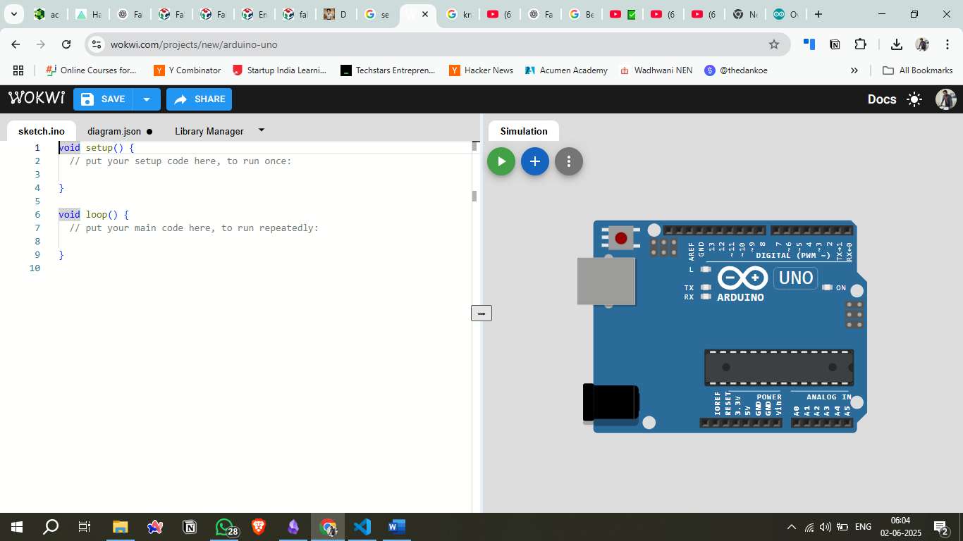
Sketch Structure
An Arduino sketch typically consists of two main functions:
- setup(): Runs once at the beginning. Used to initialize variables, pin modes, start using libraries, etc.
- loop(): Runs continuously after setup(). Contains the main logic of the program.
This structure allows the Arduino to perform tasks repeatedly, such as reading sensor data or controlling actuators.
Uploading Code to the Arduino Board
To upload your sketch to the Arduino board:
- Connect: Plug your Arduino board into your computer via USB.
- Select Board and Port:
- Go to Tools > Board and choose your Arduino model.
- Go to Tools > Port and select the appropriate COM port.
- Upload: Click the Upload button on the toolbar. The IDE will compile the code and upload it to the board.
Simulation Environment – Wokwi
Wokwi is an online simulator for Arduino, ESP32, and other microcontroller projects. It allows you to design, simulate, and debug embedded systems directly in your browser without needing any physical hardware.
Wokwi Official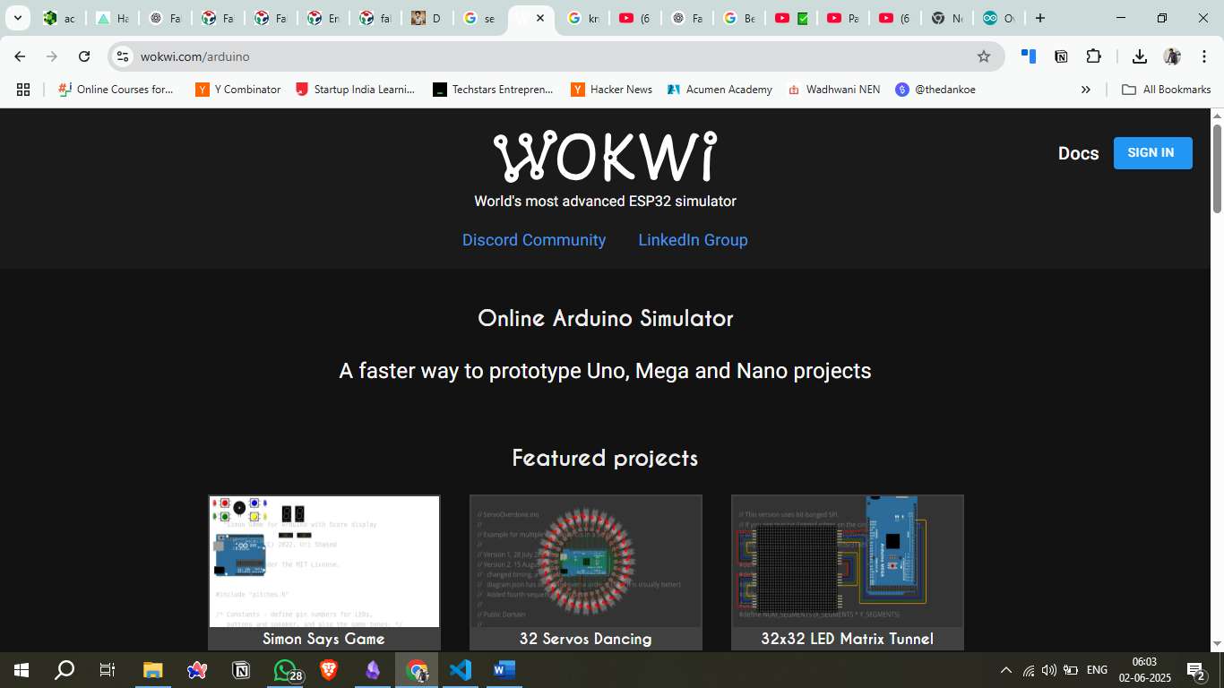
Key Features of Wokwi
- Real-time simulation of Arduino, ESP32, Raspberry Pi Pico, and more.
- Large library of components (OLED displays, sensors, buttons, etc.).
- Code editing in C++ (Arduino IDE style).
- Serial monitor and logic analyzer built-in.
- Instant feedback for testing circuits and code behavior.
- Easy to share projects via a unique URL.
Why Wokwi was used
- No need for physical components.
- Quick testing of wiring and code.
- Useful for validating OLED data display logic.
- Great for educational and prototyping purposes.
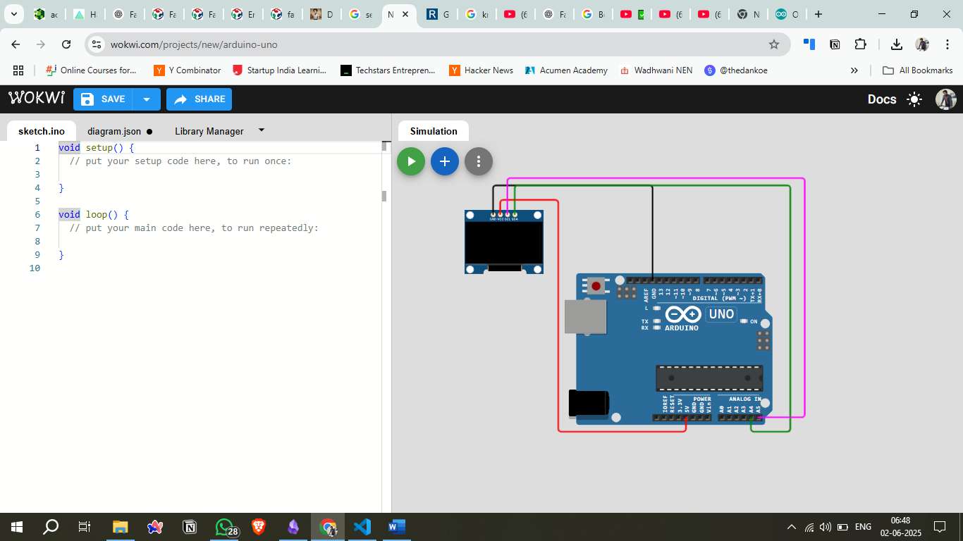
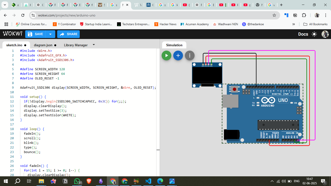
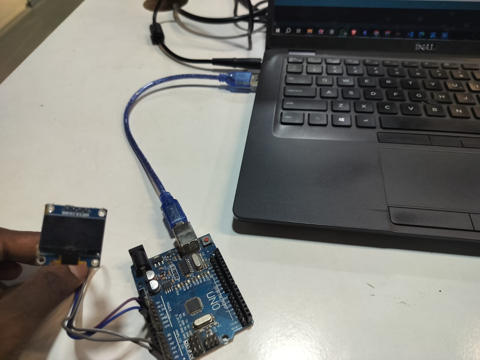
Project Summary – Arduino Uno with OLED Display
In this project, Arduino Uno was connected to a 0.96" I2C OLED Display (using the SSD1306 driver). The project was developed and tested on Wokwi to simulate real-time data display.
Project Objectives
- Connect an OLED display to Arduino Uno via I2C protocol.
- Display custom text or sensor values on the OLED screen.
- Test OLED initialization and display update logic.
Arduino
- Arduino Uno (Windows Store version 1.8.57.0)
- 0.96" OLED Display (128x64, I2C interface)
- Jumper Wires
- USB Cable
- Arduino IDE
- Libraries:
Adafruit_GFX,Adafruit_SSD1306,Wire
Library Installation
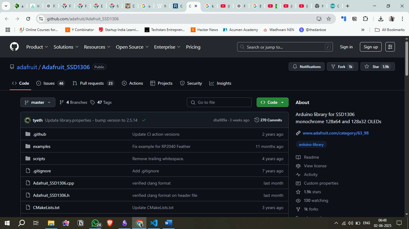
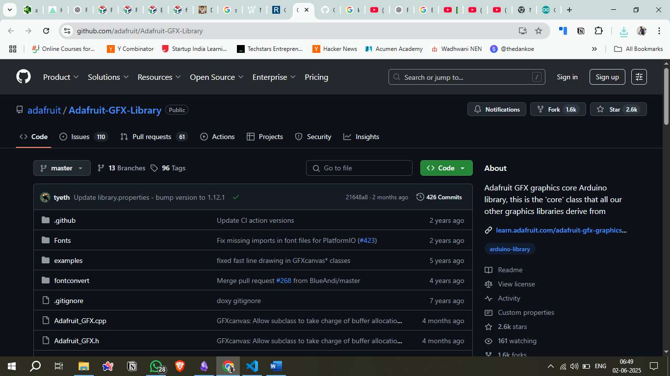
To control the OLED display, the following libraries were downloaded from GitHub and added to the Arduino IDE via: Sketch → Include Library → Add .ZIP Library
- Adafruit_SSD1306: This library supports monochrome OLEDs including 128x64 resolution.
- Adafruit_GFX: It provides core graphics functions (draw shapes, text, animations, etc.).
Circuit Connections
The OLED display connections to Arduino Uno are as follows:
- VCC → 5V
- GND → GND
- SDA → A4
- SCL → A5
Downloadable Files
Arduino Code
The following code demonstrates OLED display animations using Arduino Uno with Adafruit libraries. The code includes multiple animation effects like fade-in, scrolling text, blinking, typewriter, and bounce animations.
#include <SPI.h>
          #include <Wire.h>
          #include <Adafruit_GFX.h>
          #include <Adafruit_SSD1306.h>

          #define SCREEN_WIDTH 128 // OLED display width, in pixels
          #define SCREEN_HEIGHT 64 // OLED display height, in pixels

          // Declaration for an SSD1306 display connected to I2C (SDA, SCL pins)
          #define OLED_RESET     -1 // Reset pin # (or -1 if sharing Arduino reset pin)
          Adafruit_SSD1306 display(SCREEN_WIDTH, SCREEN_HEIGHT, &Wire, OLED_RESET);

          void setup() {
            Serial.begin(115200);

            // SSD1306_SWITCHCAPVCC = generate display voltage from 3.3V internally
            if(!display.begin(SSD1306_SWITCHCAPVCC, 0x3C)) {
              Serial.println(F("SSD1306 allocation failed"));
              for(;;); // Don't proceed, loop forever
            }

            // Show initial display buffer contents on the screen
            display.display();
            delay(2000);

            // Clear the buffer
            display.clearDisplay();
          }

          void loop() {
            // Cycle through different animations
            fadeInAnimation();
            delay(2000);

            scrollingTextAnimation();
            delay(2000);

            blinkingAnimation();
            delay(2000);

            typewriterAnimation();
            delay(2000);

            bounceAnimation();
            delay(2000);
          }

          // Animation 1: Fade in effect
          void fadeInAnimation() {
            display.clearDisplay();

            // Create fade-in effect by drawing rectangles with decreasing size
            for(int i = 20; i >= 0; i--) {
              display.clearDisplay();

              // Draw background rectangle
              display.fillRect(10 + i, 15 + i/2, 108 - 2*i, 34 - i, WHITE);
              delay(50);

              // Draw text
              display.setTextSize(3);
              display.setTextColor(BLACK);
              display.setCursor(20, 20);
              display.println(F("FAB"));
              display.setCursor(20, 40);
              display.println(F("LAB"));

              display.display();
              delay(100);
            }

            // Final clean display
            display.clearDisplay();
            display.setTextSize(3);
            display.setTextColor(WHITE);
            display.setCursor(20, 20);
            display.println(F("FAB"));
            display.setCursor(20, 40);
            display.println(F("LAB"));
            display.display();
          }

          // Animation 2: Scrolling text from right to left
          void scrollingTextAnimation() {
            display.clearDisplay();
            display.setTextSize(3);
            display.setTextColor(WHITE);

            // Scroll from right side of screen to center
            for(int x = SCREEN_WIDTH; x >= 20; x -= 4) {
              display.clearDisplay();
              display.setCursor(x, 20);
              display.println(F("FAB"));
              display.setCursor(x, 40);
              display.println(F("LAB"));
              display.display();
              delay(50);
            }
          }

          // Animation 3: Blinking effect
          void blinkingAnimation() {
            display.setTextSize(3);
            display.setTextColor(WHITE);

            for(int i = 0; i < 6; i++) {
              // Show text
              display.clearDisplay();
              display.setCursor(20, 20);
              display.println(F("FAB"));
              display.setCursor(20, 40);
              display.println(F("LAB"));
              display.display();
              delay(500);

              // Hide text
              display.clearDisplay();
              display.display();
              delay(300);
            }
          }

          // Animation 4: Typewriter effect
          void typewriterAnimation() {
            display.clearDisplay();
            display.setTextSize(3);
            display.setTextColor(WHITE);

            String text1 = "FAB";
            String text2 = "LAB";

            // Type "FAB"
            display.setCursor(20, 20);
            for(int i = 0; i < text1.length(); i++) {
              display.print(text1.charAt(i));
              display.display();
              delay(400);
            }

            delay(500);

            // Type "LAB"
            display.setCursor(20, 40);
            for(int i = 0; i < text2.length(); i++) {
              display.print(text2.charAt(i));
              display.display();
              delay(400);
            }
          }

          // Animation 5: Bounce effect
          void bounceAnimation() {
            display.setTextSize(3);
            display.setTextColor(WHITE);

            // Bounce from top to center
            for(int y = -40; y <= 20; y += 3) {
              display.clearDisplay();

              // Add some bounce physics
              int bounceY = y;
              if(y > 15) {
                bounceY = 20 - (y - 15) / 2; // Slow down as it approaches final position
              }

              display.setCursor(20, bounceY);
              display.println(F("FAB"));
              display.setCursor(20, bounceY + 20);
              display.println(F("LAB"));
              display.display();
              delay(80);
            }

            // Small final bounce
            for(int i = 0; i < 3; i++) {
              display.clearDisplay();
              display.setCursor(20, 18);
              display.println(F("FAB"));
              display.setCursor(20, 38);
              display.println(F("LAB"));
              display.display();
              delay(100);

              display.clearDisplay();
              display.setCursor(20, 20);
              display.println(F("FAB"));
              display.setCursor(20, 40);
              display.println(F("LAB"));
              display.display();
              delay(100);
            }
          }

          // Additional function: Static display with border
          void staticDisplayWithBorder() {
            display.clearDisplay();

            // Draw border
            display.drawRect(0, 0, SCREEN_WIDTH, SCREEN_HEIGHT, WHITE);
            display.drawRect(5, 5, SCREEN_WIDTH-10, SCREEN_HEIGHT-10, WHITE);

            // Display text
            display.setTextSize(3);
            display.setTextColor(WHITE);
            display.setCursor(20, 20);
            display.println(F("FAB"));
            display.setCursor(20, 40);
            display.println(F("LAB"));

            display.display();
          }