Introduction
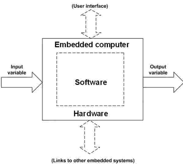
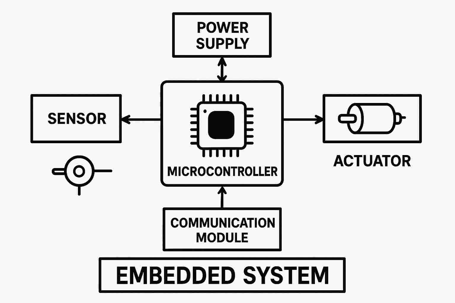
Embedded programming (EP) involves writing software that directly interacts with hardware in resource-constrained environments. It is used to control devices like sensors, motors, displays, and communication modules through microcontrollers or embedded processors. Programs, often written in C or C++, must be optimized for speed, memory usage, and power efficiency due to limited hardware capabilities. Embedded systems frequently operate in real-time, requiring fast and reliable responses to external events. Developers use debugging tools like serial monitors and JTAG/SWD interfaces to test and troubleshoot firmware, which is the permanent software stored in flash memory. Communication with other devices is often achieved through protocols like I2C, SPI, UART, or wireless methods such as Bluetooth and Wi-Fi. EP is essential in various domains including IoT, robotics, automotive systems, industrial automation, and consumer electronics, with power management being a crucial consideration, especially for battery-powered applications.
What is embedded programming
How it works
What is behind in that embedded programming
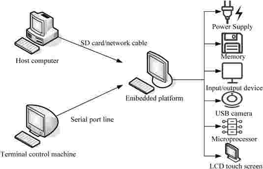
Behind embedded programming lies a combination of hardware control, software development, and system-level optimization. Here's what’s happening behind the scenes:
Why it is needed
Embedded programming is needed because it allows devices to perform specific, real-time tasks efficiently, reliably, and with minimal resources. Here's why it’s essential:
In short, embedded programming is the brain behind countless modern smart devices, making them function smoothly, efficiently, and purposefully.
This evaluation
Embedded programming evolved from simple assembly code for basic control to using C for more complex tasks. It advanced with RTOS and powerful microcontrollers, enabling multitasking and connectivity. Today, it supports AI, IoT, and smart systems with real-time capabilities.
Now it is in what stage
Now, embedded programming is in an advanced and intelligent stage, where it supports:
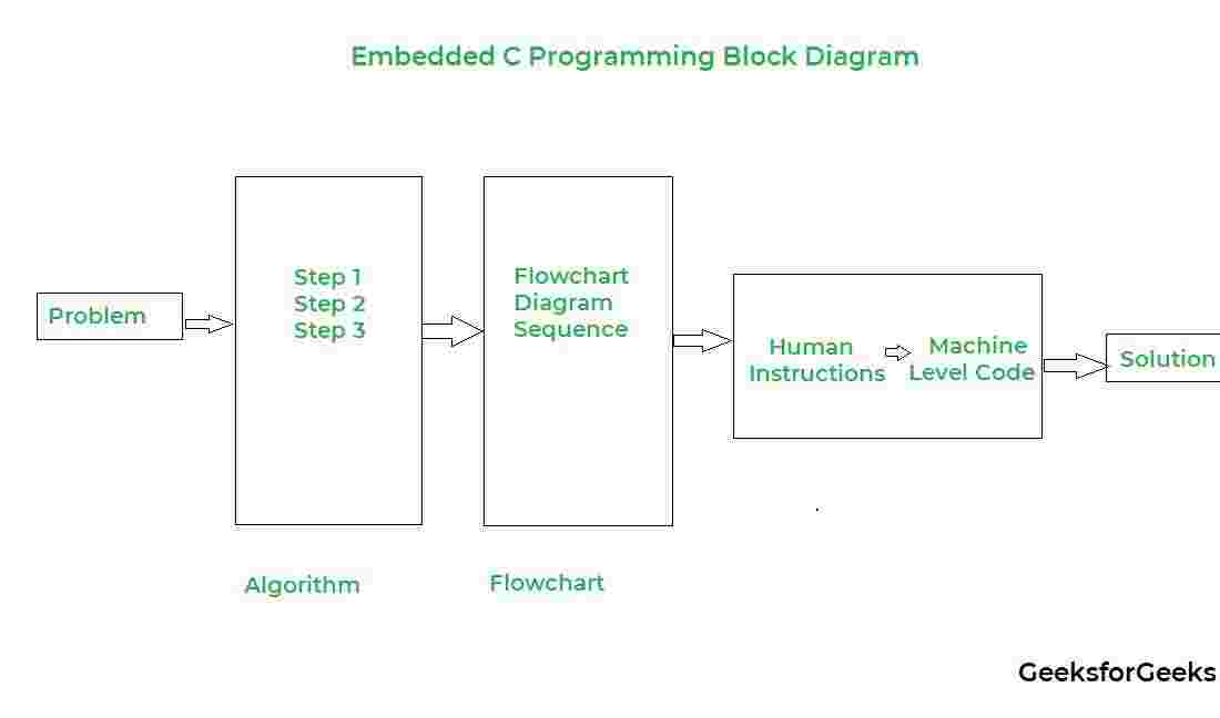
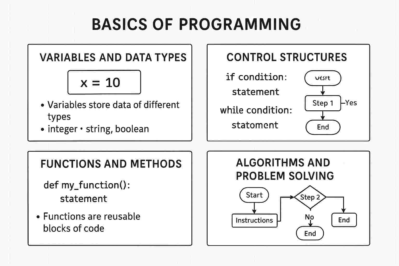
What is basics of programming
What is core programming
Core programming refers to the essential concepts of programming, such as understanding data structures, algorithms, and control structures. It focuses on problem-solving, debugging, and writing efficient code, providing the foundation for developing software across various languages like C, Python, or Java.
Comparison of microcontrollers
Item | Seeed Studio XIAO ESP32-C3 | Seeeduino XIAO | Seeed XIAO RP2040 | Seeed XIAO nRF52840 | Seeed XIAO nRF52840 Sense |
Processor | ESP32-C3 32-bit RISC-V @160MHz | SAMD21 M0+ @48MHz | RP2040 Dual-core M0+ @133MHz | nRF52840 M4F @64MHz | nRF52840 M4F @64MHz |
Wireless Connectivity | WiFi and Bluetooth 5 (BLE) | N/A | N/A | Bluetooth 5.0 / BLE / NFC | Bluetooth 5.0 / BLE / NFC |
Memory | 400KB SRAM, 4MB Flash | 32KB SRAM, 256KB Flash | 264KB SRAM, 2MB Flash | 256KB RAM, 1MB + 2MB Flash | 256KB RAM, 1MB + 2MB Flash |
Built-in Sensors | N/A | N/A | N/A | N/A | 6 DOF IMU (LSM6DS3TR-C), Microphone |
Interfaces | I2C / UART / SPI | I2C / UART / SPI | I2C / UART / SPI | I2C / UART / SPI | I2C / UART / SPI |
PWM / Analog Pins | 11 / 4 | 11 / 11 | 11 / 4 | 11 / 6 | 11 / 6 |
Onboard Buttons | Reset / Boot Button | N/A | Reset / Boot Button | Reset Button | Reset Button |
Onboard LEDs | Charge LED | N/A | Full-color RGB LED | 3-in-one LED / Charge LED | 3-in-one LED / Charge LED |
Battery Charge Chip | ETA4054S2F | N/A | N/A | BQ25101 | BQ25101 |
Programming Languages | Arduino / MicroPython | Arduino / CircuitPython | Arduino / MicroPython / CircuitPython | Arduino / MicroPython | Arduino / MicroPython |
link
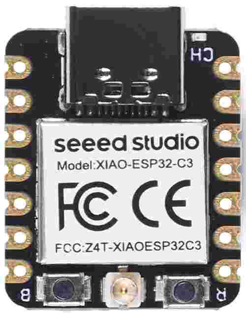
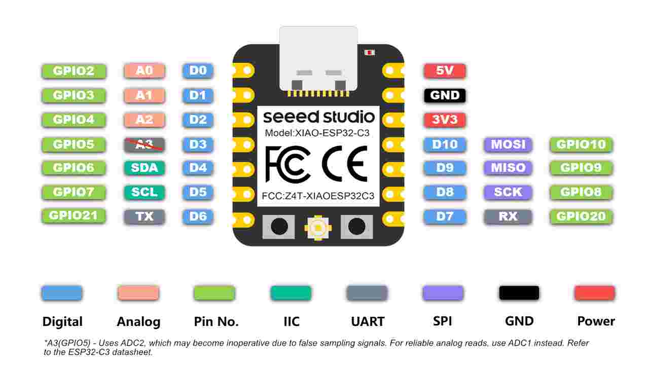
The Seeed Studio XIAO ESP32-C3 is a tiny board used for creating smart devices that connect to the internet or use Bluetooth. It runs on a 32-bit RISC-V processor, which makes it fast and efficient. It can connect to WiFi and Bluetooth 5 (BLE), making it great for wireless projects. It comes with a small antenna that helps make the signal stronger. The board is small in size and can be easily added to other circuits since it only needs one side to be mounted. It has several pins that can be used to connect sensors or other parts—11 pins for digital signals, which can also be used for controlling motors or lights, and 3 pins for reading values like temperature or light. It supports different ways to communicate with other devices, like UART, I2C, and SPI. There are two small buttons on the board—one to reset it and another to put it in a special mode for updating the software. It works well with Grove Shield and other accessories made for Seeeduino XIAO, except for one expansion board where the spring contact pins don’t match. Overall, this board is great for making small, smart gadgets that don’t use much power, like wearable tech or low-power IoT projects.
features:
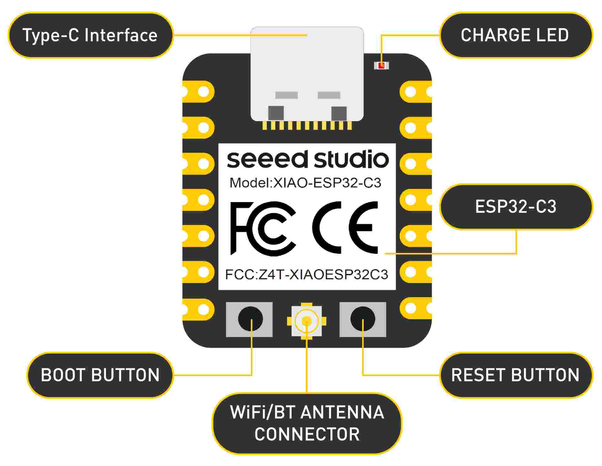
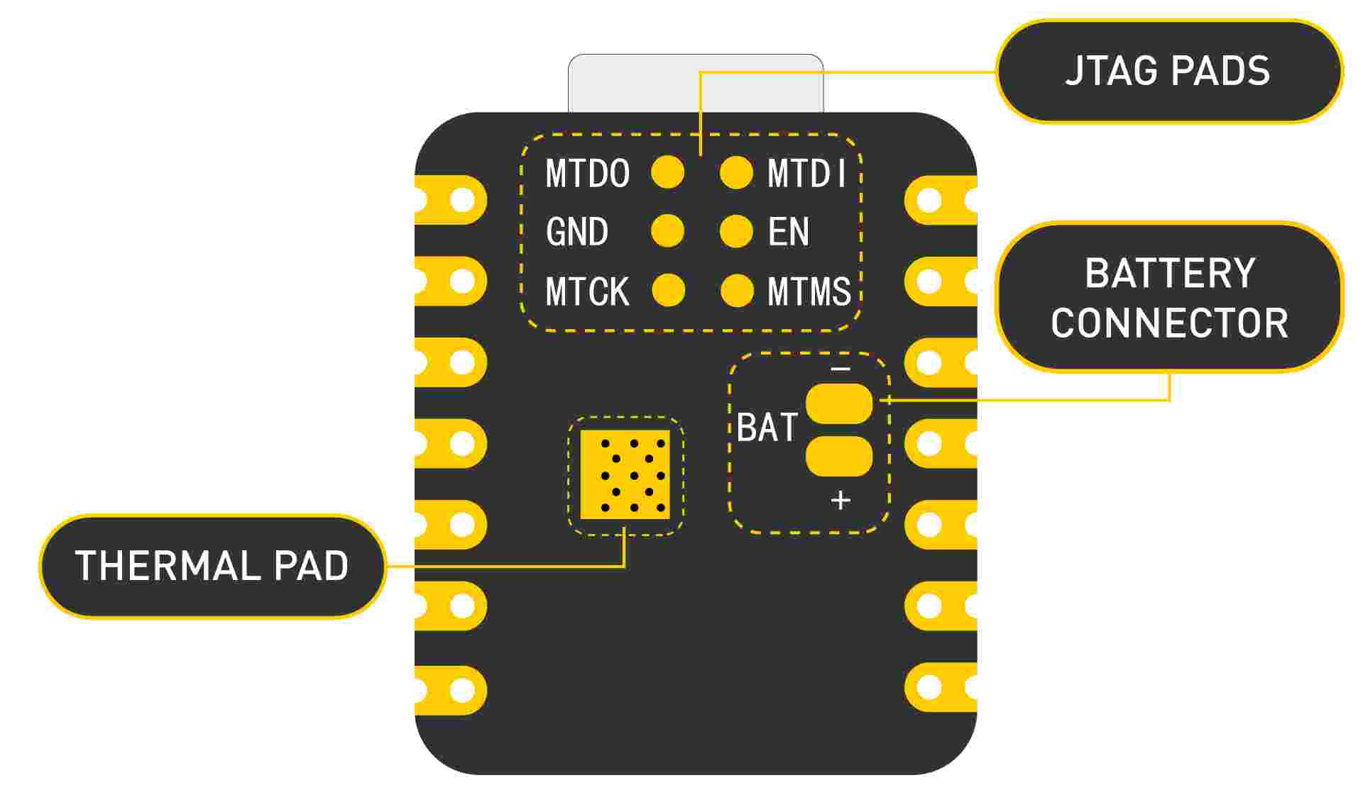
Hardware overview
XIAO ESP32-C3 front indication diagram XIAO ESP32-C3 back indication diagram
XIAO ESP32-C3 Pin List
Power Consumption
Operating Voltage
Charging Current
Power Pins
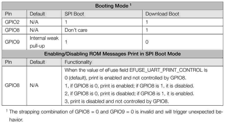
Strapping Pins
As per the ESP32-C3 chip manual, GPIO2, GPIO8, and GPIO9 are called Strapping Pins. The high or low signal levels on these pins during startup can change how the chip boots. So, when using these pins, be careful—if not used properly, your XIAO might not upload code or run your program correctly.
Getting started
First, we are going to connect XIAO ESP32-C3 to the computer, connect an LED to the board and upload a simple code from Arduino IDE to check whether the board is functioning well by blinking the connected LED.
Hardware Preparation
You need to prepare the following:
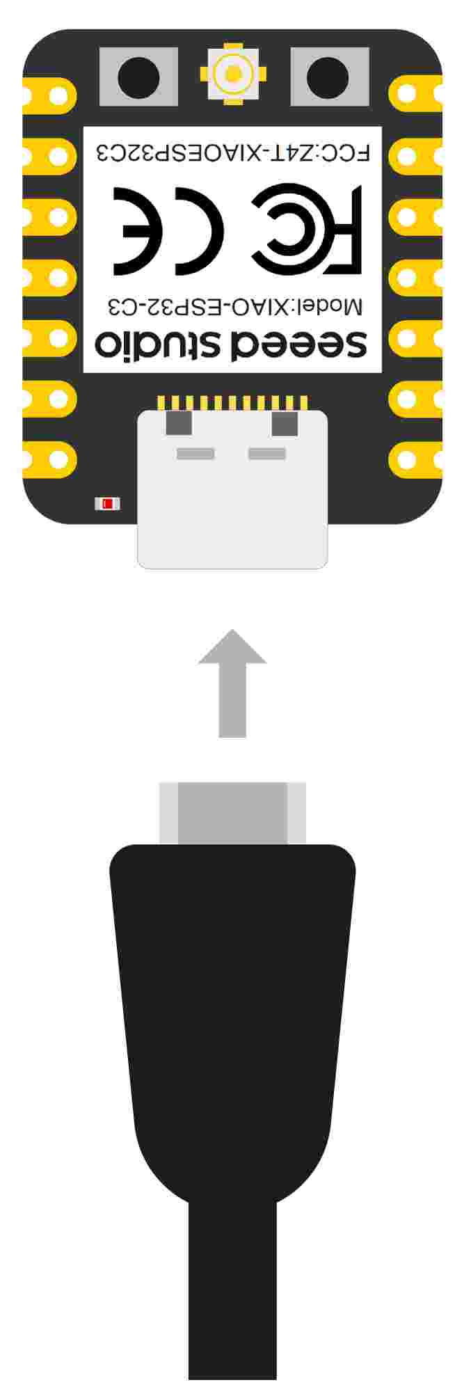
Step 1. Connect XIAO ESP32-C3 to your computer via a USB Type-C cable.
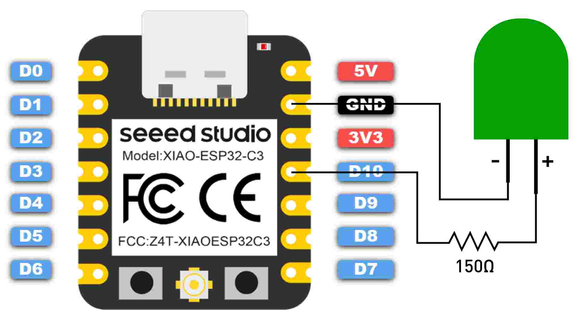
Step 2. Connect an LED to D10 pin as follows
Note: Make sure to connect a resistor (about 150Ω) in series to limit the current through the LED and to prevent excess current that can burn out the LED
Software Preparation
Step 1. Download and Install the latest version of Arduino IDE according to your operating system
Step 2. Launch the Arduino application
Step 3. Add ESP32 board package to your Arduino IDE
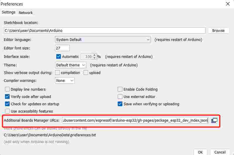
Navigate to File > Preferences, and fill "Additional Boards Manager URLs" with the url below: URL
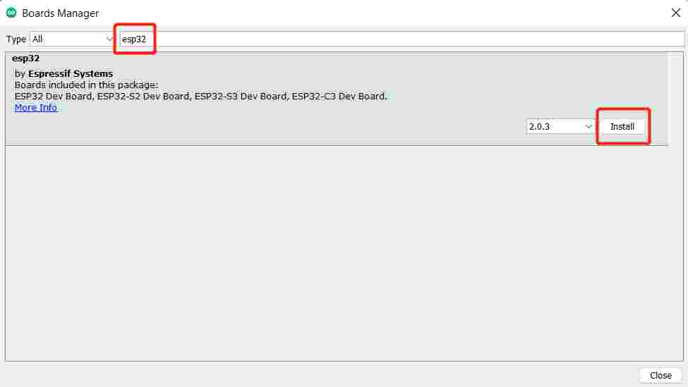
Navigate to Tools > Board > Boards Manager..., type the keyword "esp32" in the search box, select the latest version of esp32, and install it.
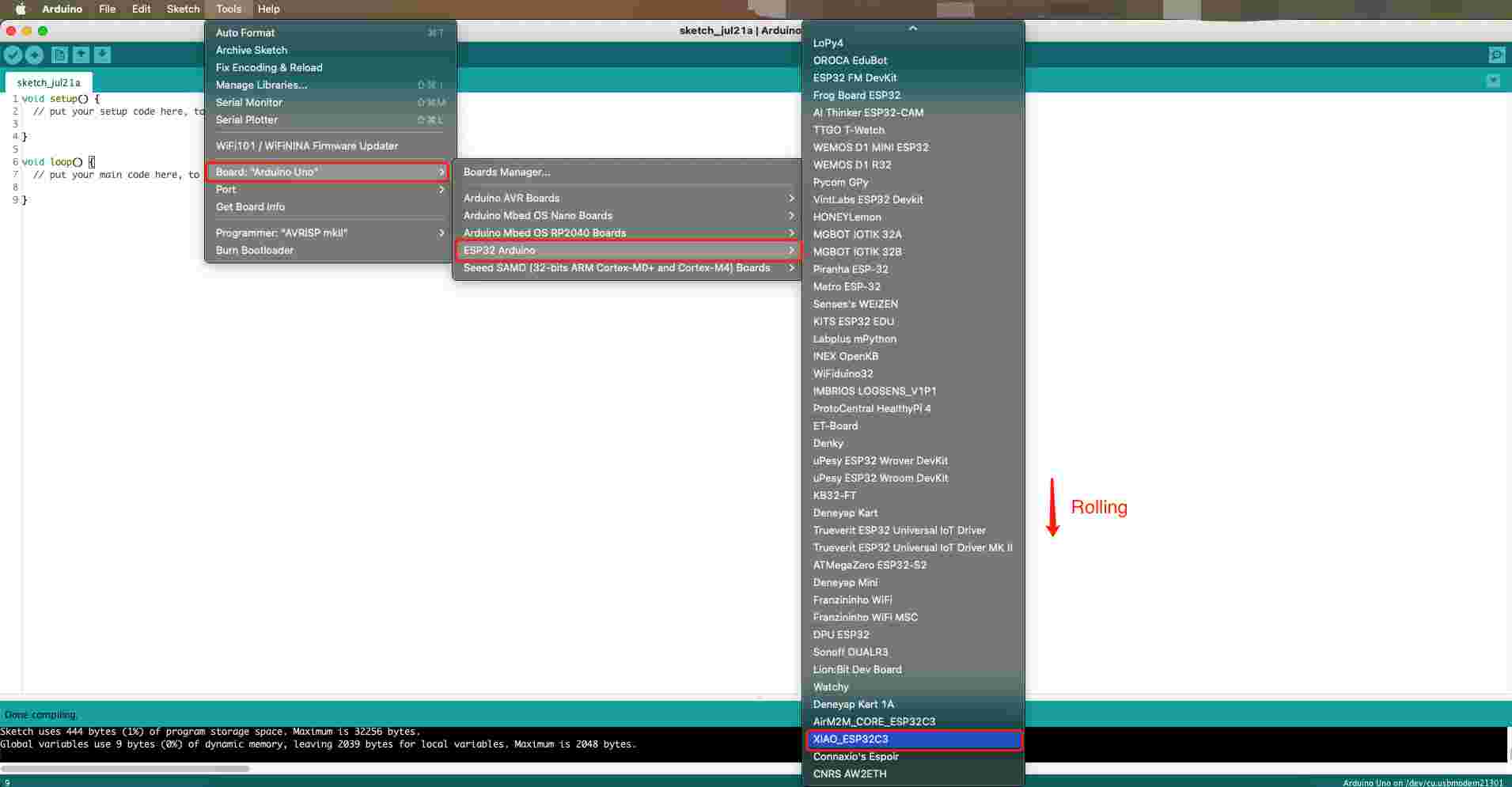
Step 4. Select your board and port
Board
Navigate to Tools > Board > ESP32 Arduino and select "XIAO_ESP32-C3". The list of board is a little long and you need to roll to the buttom to reach it.
Port
Navigate to Tools > Port and select the serial port name of the connected XIAO ESP32-C3. This is likely to be COM3 or higher (COM1 and COM2 are usually reserved for hardware serial ports).
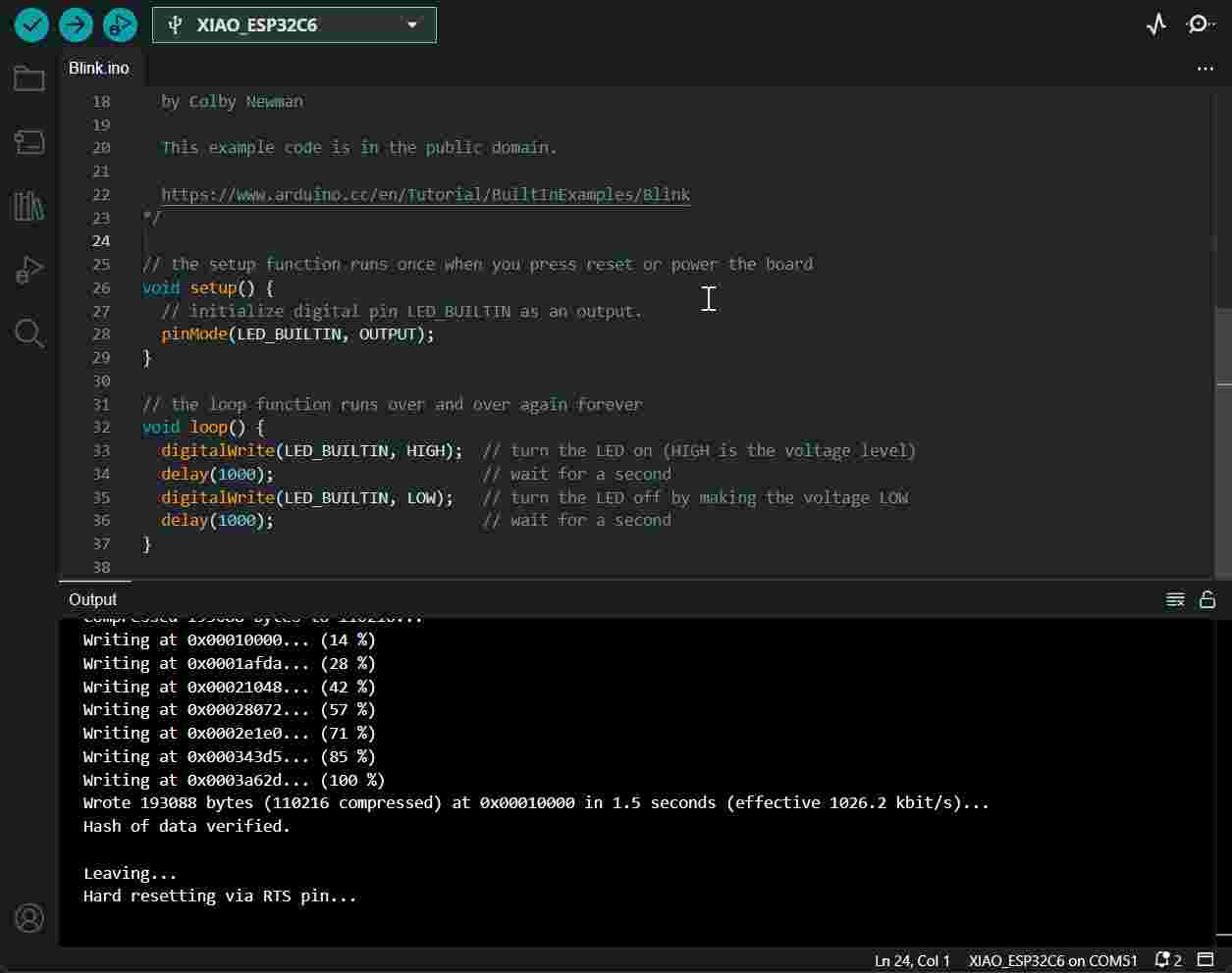
My first Blink program
Step 1. Copy the below code to Arduino IDE
Make sure your D10 is connected to an LED as shown in the diagram above.
// define led according to pin diagram in article
const int led = D10; // there is no LED_BUILTIN available for the XIAO ESP32-C3.
void setup() {
// initialize digital pin led as an output
pinMode(led, OUTPUT);
}
void loop() {
digitalWrite(led, HIGH); // turn the LED on
delay(1000); // wait for a second
digitalWrite(led, LOW); // turn the LED off
delay(1000); // wait for a second
}
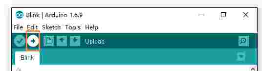
Step 2. Click the Upload button to upload the code to the board
Once uploaded, you will see the connected LED blinking with a 1-second delay between each blink. This means the connection is successful and now you can explore more projects with XIAO ESP32-C3!
Battery Usage
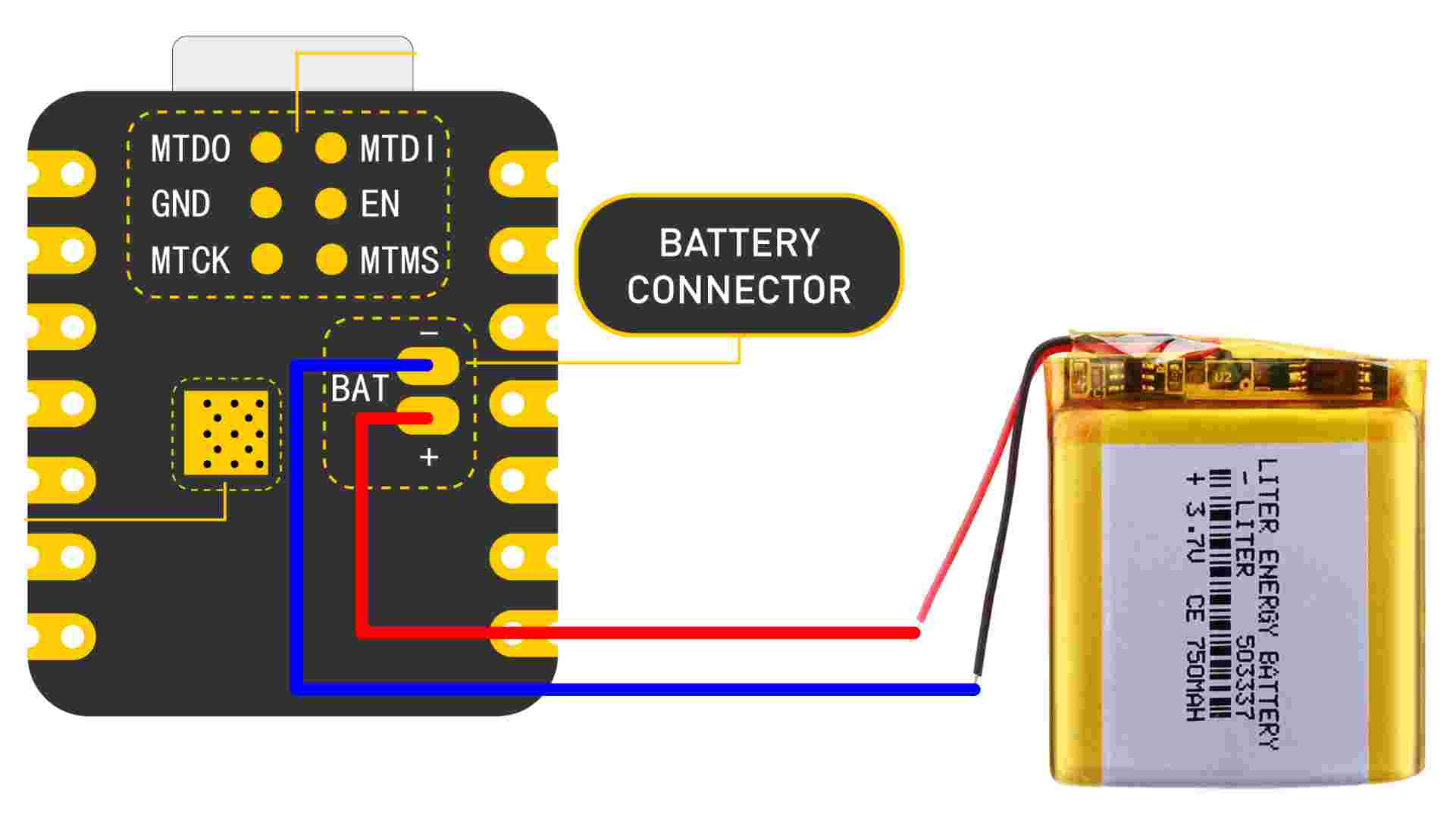
The XIAO ESP32-C3 is capable of using a 3.7V lithium battery as the power supply input. You can refer to the following diagram for the wiring method.
caution: Please be careful not to short-circuit the positive and negative terminals and burn the battery and equipment when soldering.
Instructions on the use of batteries:
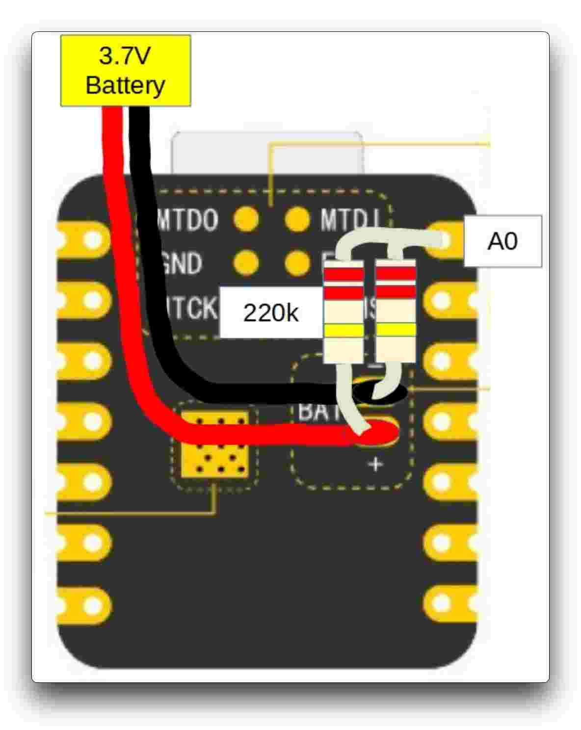
Check the battery voltage
The datasheet says the ADC full scale is 2500mV, but it can vary ±10% between chips. For example, one chip showed 2700mV. Luckily, each chip has a calibration value stored in its fuse area, and using analogReadMilliVolts() gives corrected voltage readings automatically.
Readings closely match multimeter values with only about 5mV error, which is fine for practical use. However, during communication, spikes may occur, so averaging the readings (e.g., 16 times) helps smooth out the results.
The following is the procedure to test the battery voltage.
void setup() {
Serial.begin(115200);
pinMode(A0, INPUT); // ADC
}
void loop() {
uint32_t Vbatt = 0;
for(int i = 0; i < 16; i++) {
Vbatt = Vbatt + analogReadMilliVolts(A0); // ADC with correction
}
float Vbattf = 2 * Vbatt / 16 / 1000.0; // attenuation ratio 1/2, mV --> V
Serial.println(Vbattf, 3);
delay(1000);
}
Deep sleep mode and wake-up
The XIAO ESP32-C3 is designed to support deep sleep mode and wake-up functions. For the use of these two functions, we provide the following usage examples.
#define BUTTON_PIN_BITMASK 0x200000000 // 2^33 in hex
RTC_DATA_ATTR int bootCount = 0;
/*
Method to print the reason by which ESP32
has been awaken from sleep
*/
void print_wakeup_reason(){
esp_sleep_wakeup_cause_t wakeup_reason;
wakeup_reason = esp_sleep_get_wakeup_cause();
switch(wakeup_reason)
{
case ESP_SLEEP_WAKEUP_EXT0 : Serial.println("Wakeup caused by external signal using RTC_IO"); break;
case ESP_SLEEP_WAKEUP_EXT1 : Serial.println("Wakeup caused by external signal using RTC_CNTL"); break;
case ESP_SLEEP_WAKEUP_TIMER : Serial.println("Wakeup caused by timer"); break;
case ESP_SLEEP_WAKEUP_TOUCHPAD : Serial.println("Wakeup caused by touchpad"); break;
case ESP_SLEEP_WAKEUP_ULP : Serial.println("Wakeup caused by ULP program"); break;
default : Serial.printf("Wake Up was not caused by deep sleep: %d\n",wakeup_reason); break;
}
}
void setup(){
Serial.begin(115200);
delay(1000); //Take some time to open up the Serial Monitor
//Increment boot number and print it every reboot
++bootCount;
Serial.println("Boot number: " + String(bootCount));
//Print the wakeup reason for ESP32
print_wakeup_reason();
esp_deep_sleep_enable_gpio_wakeup(BIT(D1), ESP_GPIO_WAKEUP_GPIO_LOW);
//Go to sleep now
Serial.println("Going to sleep now");
esp_deep_sleep_start();
Serial.println("This will never be printed");
}
void loop(){
//This is not going to be called
}
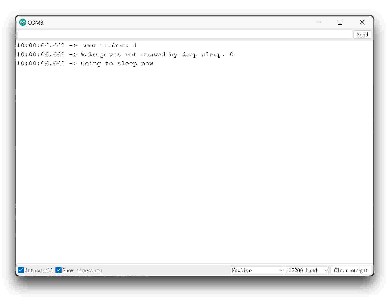
If you are quick enough to turn on the serial monitor before the XIAO goes into deep sleep, then you can see the message output as shown below. This means that the XIAO is now "asleep".
Tip: After XIAO enters deep sleep, its port disappears. You'll need to wake it up to see the port again. A low signal on D1 (e.g., pressing a button connected to D1) can wake it.
Caution: Only GPIO wake-up is supported, and only pins D0 to D3 can be used for this. Other pins won't work for wake-up.
Seeed Studio XIAO ESP32C6
introduction:
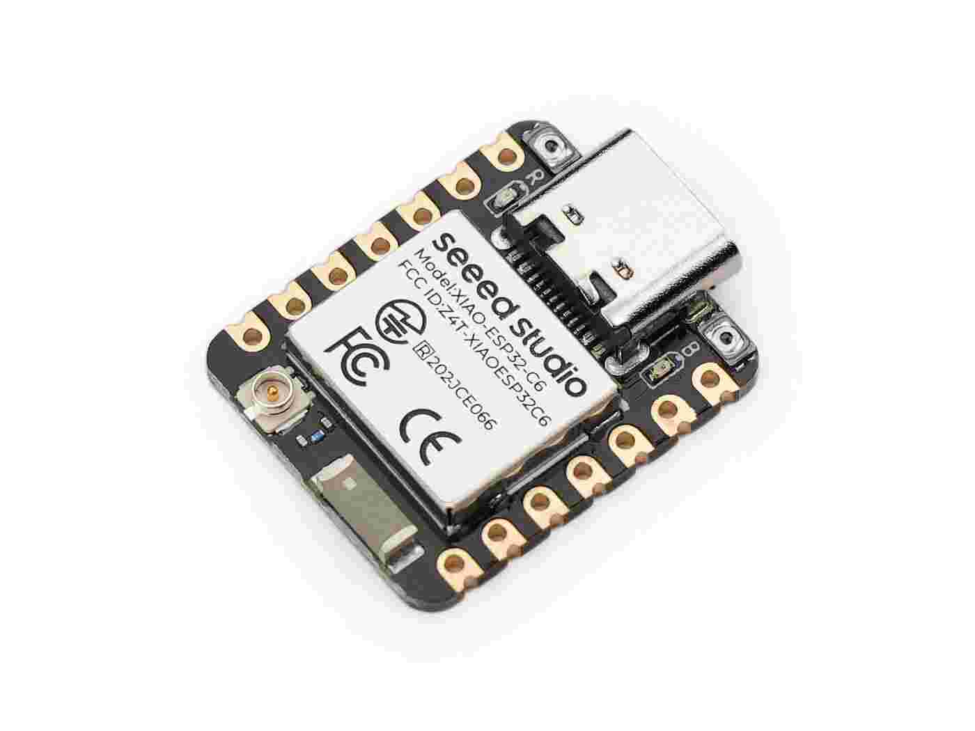
The Seeed Studio XIAO ESP32C6 is a compact board with dual 32-bit RISC-V processors—one high-performance (160 MHz) and one low-power (20 MHz). It includes 512KB SRAM and 4MB Flash for flexible IoT applications. With built-in support for WiFi 6 (2.4 GHz), Bluetooth 5.3, Zigbee, and Thread, it’s the first XIAO board ready for Matter, making it ideal for smart home and interoperable IoT projects.
comparison
Products | XIAO ESP32C6 | XIAO ESP32-C3 | XIAO ESP32S3 |
Processor | Espressif ESP32-C6 SoC | Espressif ESP32-C3 SoC | Espressif ESP32-S3R8 |
Two 32-bit RISC-V processors (160 MHz & 20 MHz) | RISC-V single-core 32-bit (up to 160 MHz) | Xtensa LX7 dual-core 32-bit (up to 240 MHz) | |
Wireless | 2.4GHz Wi-Fi 6, BLE 5.0, Bluetooth Mesh, Zigbee, Thread, IEEE 802.15.4 | 2.4GHz Wi-Fi, BLE 5.0, Bluetooth Mesh | 2.4GHz Wi-Fi, BLE 5.0, Bluetooth Mesh |
On-chip Memory | 512KB SRAM & 4MB Flash | 400KB SRAM & 4MB Flash | 8M PSRAM & 8MB Flash |
Interface | 1x UART, 1x LP_UART, 1x IIC, 1x LP_IIC, 1x SPI, 11x GPIO (PWM), 7x ADC, 1x SDIO | 1x UART, 1x IIC, 1x SPI, 11x GPIO (PWM), 4x ADC | 1x UART, 1x IIC, 1x IIS, 1x SPI, 11x GPIO (PWM), 9x ADC, 1x User LED, 1x Charge LED, 1x Reset button, 1x Boot button |
Dimensions | 21 x 17.8 mm | 21 x 17.8 mm | 21 x 17.8 mm |
Power | Type-C: 5V, BAT: 4.2V | Type-C: 5V, BAT: 3.8V | Type-C: 5V, BAT: 3.8V |
Power Consumption Model (Supply Power: 3.8V) | Modem-sleep Model ~ 30 mA, Light-sleep Model ~ 2.5 mA, Deep Sleep Model ~ 15 μA | Modem-sleep Model ~ 24 mA, Light-sleep Model ~ 3 mA, Deep Sleep Model ~ 44 μA | Modem-sleep Model ~ 25 mA, Light-sleep Model ~ 2 mA, Deep Sleep Model ~ 14 μA |
Charging Battery Current | 100mA | 350mA | 100mA |
Working Temperature | -40°C ~ 85°C | -40°C ~ 65°C | -40°C ~ 85°C |
Features:
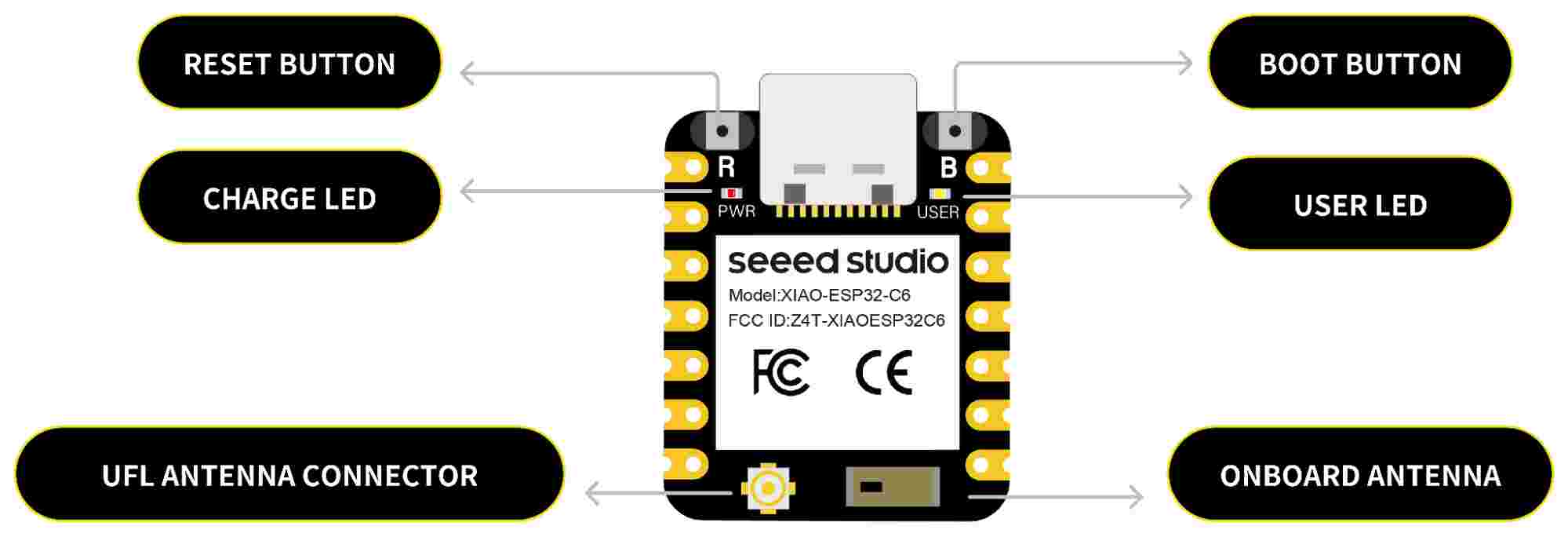
Hardware overview
XIAO ESP32C6 indication diagram
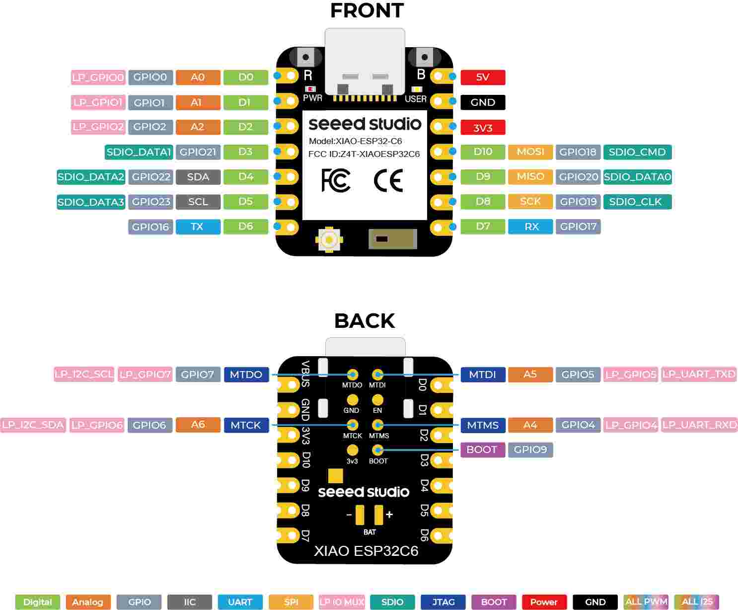
XIAO ESP32C6 Pin List
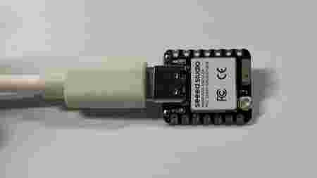
To begin working with the XIAO ESP32C6, you need to gather the following hardware components:
Tip: Make sure the USB cable is capable of transferring data. Some USB cables only supply power, and if you're unsure, check if your USB cable supports USB 3.1 for data transfer.
Additionally, the XIAO ESP32C6 is shipped without pin headers. To connect it to an expansion board or sensor, you need to solder the pin headers. Be careful while soldering due to the small size of the board. Improper soldering can cause shorts or prevent the device from functioning.
Sometimes, you may encounter an issue where the XIAO ESP32C6 does not appear to be connected to your computer, or the upload process fails. To resolve this, you can enter BootLoader Mode by following these steps:
This process is useful if the XIAO appears as a disconnected device or fails to upload code properly.
The Arduino IDE is recommended for programming the XIAO ESP32C6. Below are the steps for setting up the software:
The XIAO ESP32C6 has a built-in power management chip that enables it to be powered either by a USB connection or a rechargeable 3.7V lithium battery. To connect the battery:
Battery Soldering:
Caution: While using battery power, there will be no voltage present on the 5V pin.
The XIAO ESP32C6 features a red indicator light to indicate charging status:
To monitor the battery voltage, you can use an analog-to-digital converter (ADC) on the A0 port. You'll need to solder a 200k resistor to create a voltage divider (1:2 ratio) to safely monitor the voltage.
Sample Code for Monitoring Battery Voltage:
#include <Arduino.h>
void setup() {
Serial.begin(115200);
pinMode(A0, INPUT); // Configure A0 as ADC input
}
void loop() {
uint32_t Vbatt = 0;
for(int i = 0; i < 16; i++) {
Vbatt += analogReadMilliVolts(A0); // Read and accumulate ADC voltage
}
float Vbattf = 2 * Vbatt / 16 / 1000.0; // Adjust for 1:2 divider and convert to volts
Serial.println(Vbattf, 3); // Output voltage to 3 decimal places
delay(1000); // Wait for 1 second
}
This code reads the voltage on the A0 pin and adjusts for the 1:2 voltage divider to output the battery voltage in volts.
The XIAO ESP32C6 supports deep sleep mode to save power, which is especially useful for IoT applications. There are two common ways to wake up the device from deep sleep:
#define BUTTON_PIN_BITMASK (1ULL << GPIO_NUM_0) // GPIO 0 bitmask for ext1
RTC_DATA_ATTR int bootCount = 0;
void print_wakeup_reason(){
esp_sleep_wakeup_cause_t wakeup_reason;
wakeup_reason = esp_sleep_get_wakeup_cause();
switch(wakeup_reason) {
case ESP_SLEEP_WAKEUP_EXT0 : Serial.println("Wakeup caused by external signal"); break;
case ESP_SLEEP_WAKEUP_TIMER : Serial.println("Wakeup caused by timer"); break;
default : Serial.println("Wakeup caused by another source"); break;
}
}
void setup(){
Serial.begin(115200);
++bootCount;
print_wakeup_reason();
esp_sleep_enable_ext1_wakeup(BUTTON_PIN_BITMASK, ESP_EXT1_WAKEUP_ANY_HIGH);
Serial.println("Going to sleep now");
esp_deep_sleep_start();
}
void loop() {
// Not used in this demo
}
This code uses an external button connected to GPIO 0 to wake up the device from deep sleep.
#define uS_TO_S_FACTOR 1000000ULL // Conversion factor to seconds
#define TIME_TO_SLEEP 5 // Sleep time in seconds
RTC_DATA_ATTR int bootCount = 0;
void print_wakeup_reason(){
esp_sleep_wakeup_cause_t wakeup_reason = esp_sleep_get_wakeup_cause();
switch(wakeup_reason) {
case ESP_SLEEP_WAKEUP_TIMER : Serial.println("Wakeup caused by timer"); break;
default : Serial.println("Wakeup caused by another source"); break;
}
}
void setup(){
Serial.begin(115200);
++bootCount;
print_wakeup_reason();
esp_sleep_enable_timer_wakeup(TIME_TO_SLEEP * uS_TO_S_FACTOR);
Serial.println("Going to sleep now");
esp_deep_sleep_start();
}
void loop() {
// Not used in this demo
}
In this example, the ESP32C6 will wake up every 5 seconds after entering deep sleep, powered by a timer.
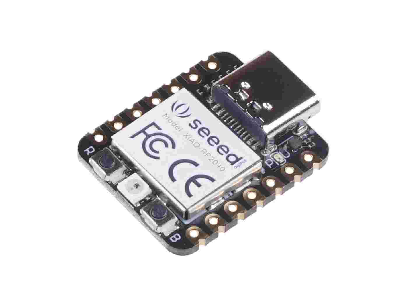
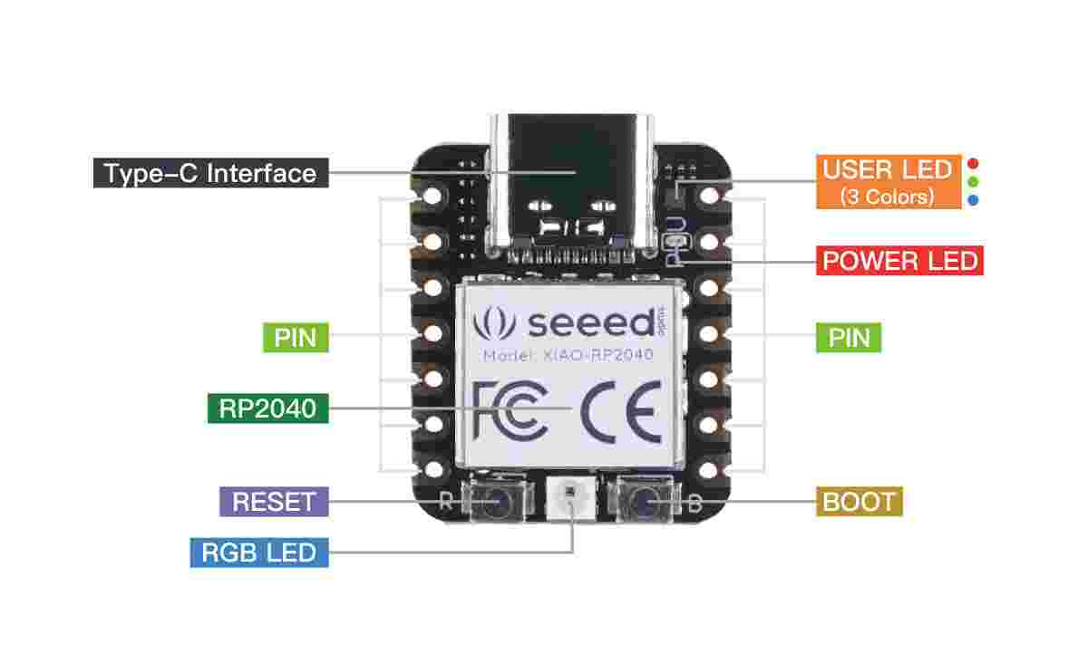
Seeed Studio XIAO RP2040
Introduction:
The Seeed Studio XIAO RP2040 is a compact yet powerful microcontroller board, measuring just 21x17.8mm, similar in size to the XIAO SAMD21 but offering greater performance. It features the Dual-core RP2040 processor, capable of running up to 133 MHz while maintaining low power consumption. The board includes 264KB of SRAM and 2MB of on-board Flash memory, providing ample space for programs.
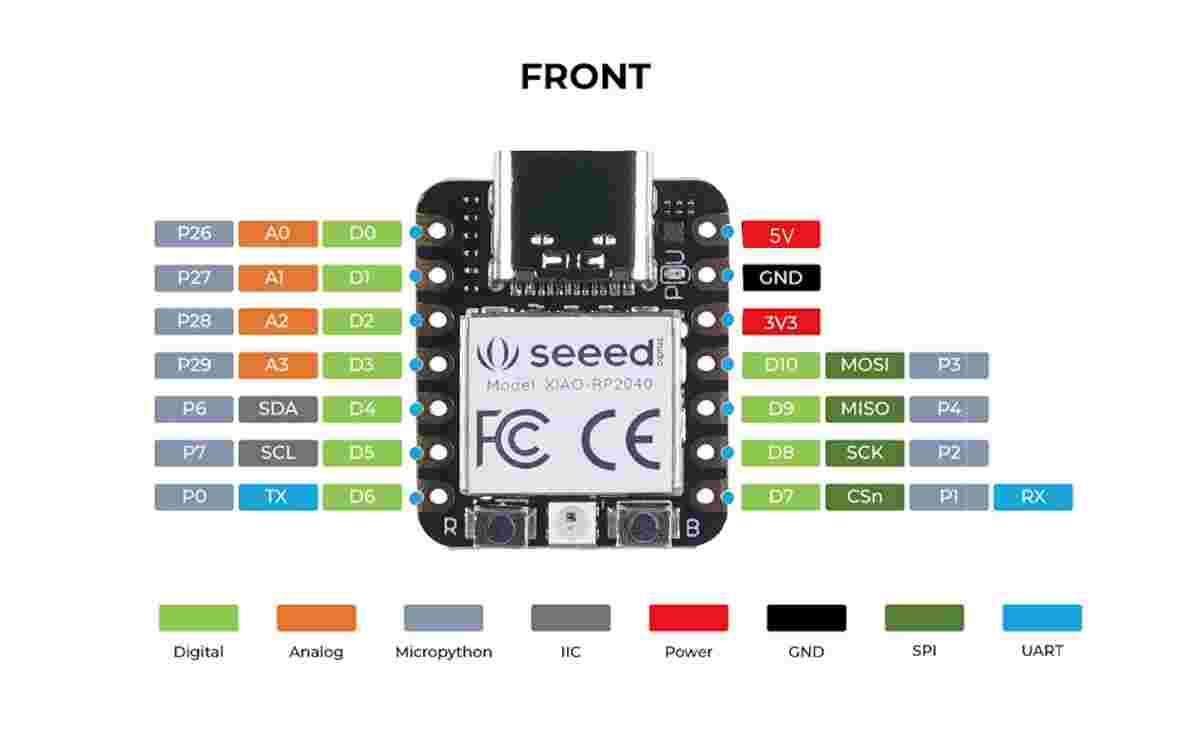
It comes with 14 GPIO pins, which include:
Due to its small form factor and good performance, it's ideal for wearable devices and compact projects. The XIAO RP2040 is compatible with Seeed's XIAO expansion boards for easy prototyping and additional functionality.
features:
Specification
Item | Value |
CPU | Dual-core ARM Cortex M0+ up to 133MHz |
Flash Memory | 2MB |
SRAM | 264KB |
Digital I/O Pins | 11 |
Analog I/O Pins | 4 |
PWM Pins | 11 |
I2C Interface | 1 |
SPI Interface | 1 |
UART Interface | 1 |
Power Supply & Downloading Interface | Type-C |
Power | 3.3V/5V DC |
Dimensions | 21×17.8×3.5mm |
Hardware Overview
Caution:
Bootloader Mode:
Reset:
MICROCONTROLLERS(ESP8266 AND ESP32 WROOM 32E)
I studied and compared the datasheets of both ESP8266 and ESP32-WROOM-32E modules to understand their architecture, pin configuration, memory layout, power management, and communication protocols (SPI, I2C, UART).
COMPARISON:
Feature | ESP8266 | ESP32-WROOM-32E |
Core | Single-core (80–160 MHz) | Dual-core (up to 240 MHz) |
RAM | ~50 KB | 520 KB SRAM + optional PSRAM |
Flash | Up to 16 MB (external) | 4–16 MB (external SPI flash) |
GPIOs | 17 GPIOs | Up to 26 GPIOs |
ADC Channels | 1 (10-bit) | Multiple (12-bit) |
Touch Sensor | Not supported | 10 capacitive touch channels |
Wi-Fi | Yes (2.4 GHz) | Yes (2.4 GHz) |
Bluetooth | Not available | Bluetooth Classic + BLE |
UART/SPI/I2C | UART ×2, SPI ×2, I2C (soft) | UART ×3, SPI ×4, I2C ×2 |
Power Efficiency | Lower consumption | Better low-power modes, but more power usage overall |
Security Features | Basic WPA/WEP | Secure Boot, Flash Encryption, WPA3 |
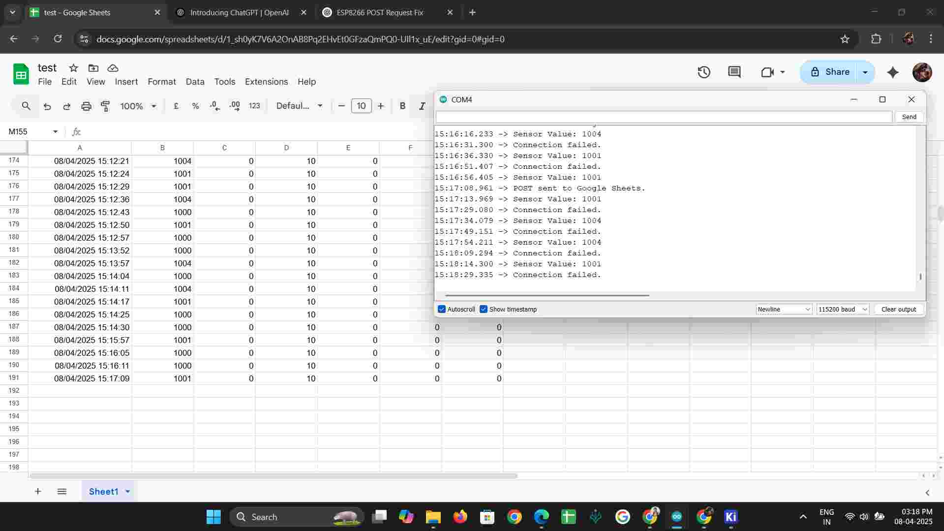
ESP8266 ANALYSIS USING GENERAL CAPACITIVE TOUCH SENSOR
void sendToGoogleSheets(int value) {
if (client.connect("script.google.com", 443)) {
String payload = "{\"accX\":" + String(value) +
",\"accY\":0,\"accZ\":0,\"gyroX\":0,\"gyroY\":0,\"gyroZ\":0}";
String url =
"/macros/s/AKfycbwoFLh5w9IE0WJ9Q7RBizoxRd9_2_7FD-lRU1i1VRlzMU37BmOcnzakcTstzXuDBmuh/
exec";
client.println("POST " + url + " HTTP/1.1");
client.println("Host: script.google.com");
client.println("Content-Type: application/json");
client.println("Content-Length: " + String(payload.length()));
client.println();
client.println(payload);
Serial.println("POST sent to Google Sheets.");
} else {
Serial.println("Connection failed.");
}
}
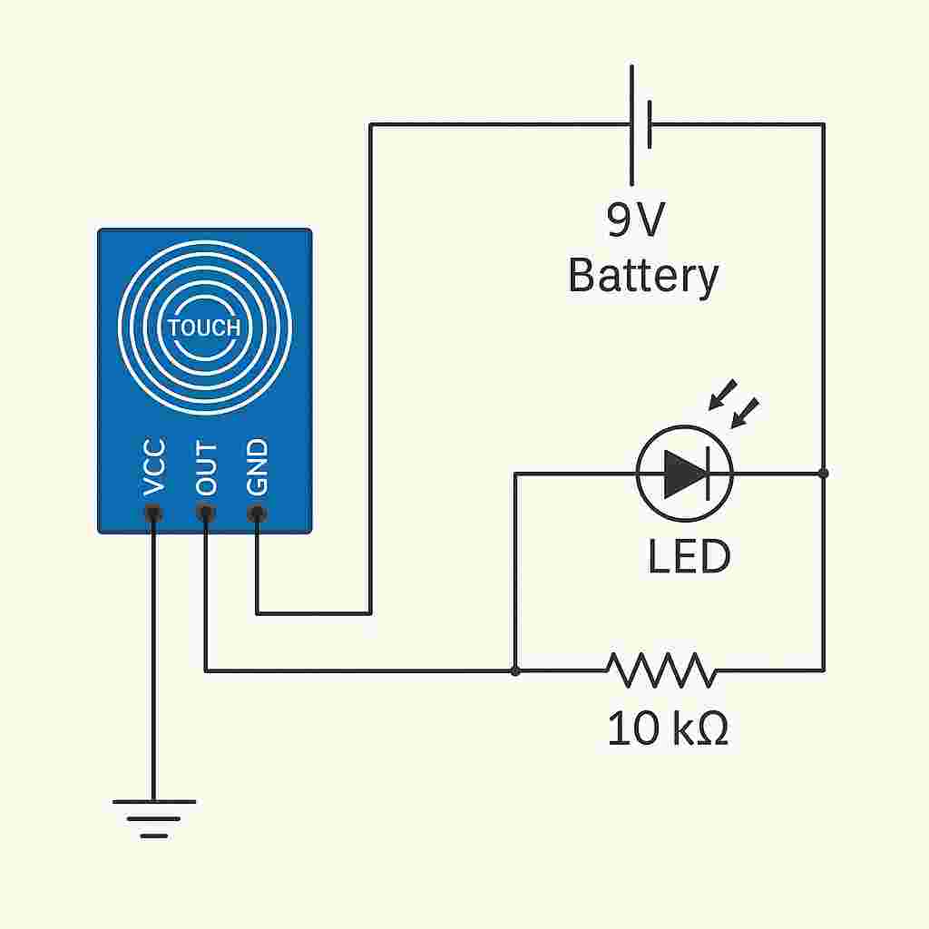
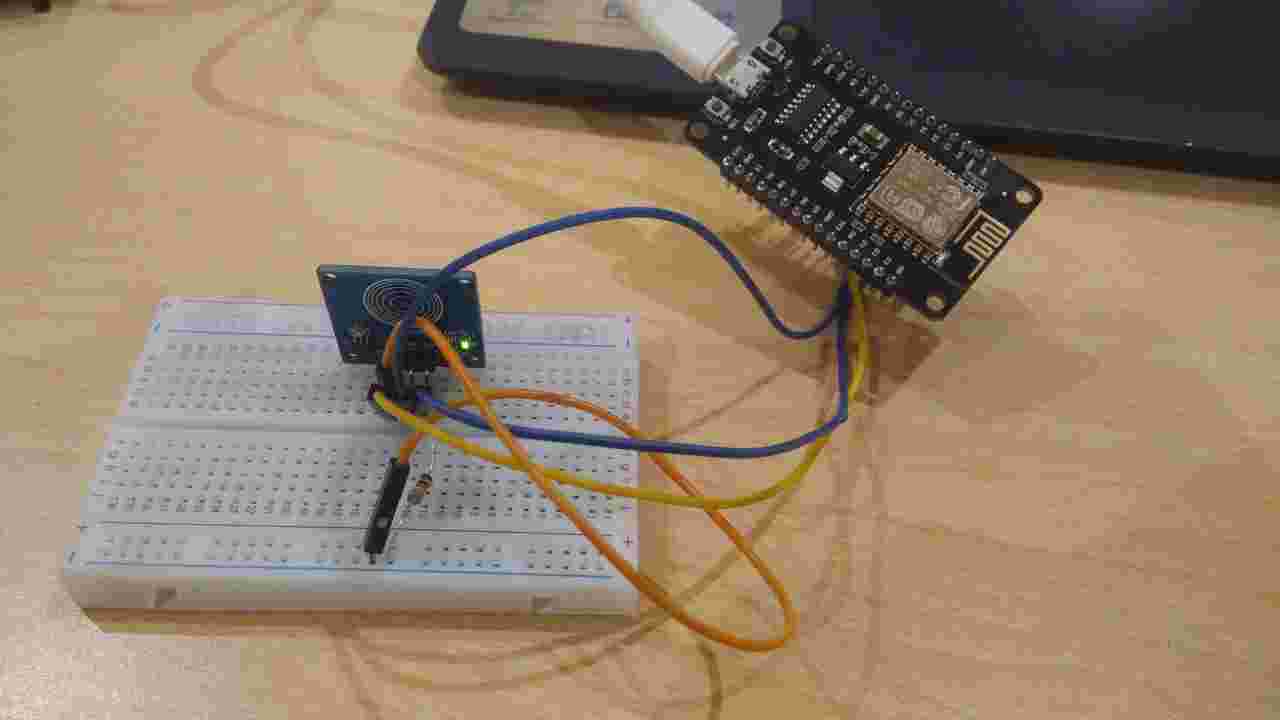
3.Interface touch sensor with ESP8266
CONNECTION:
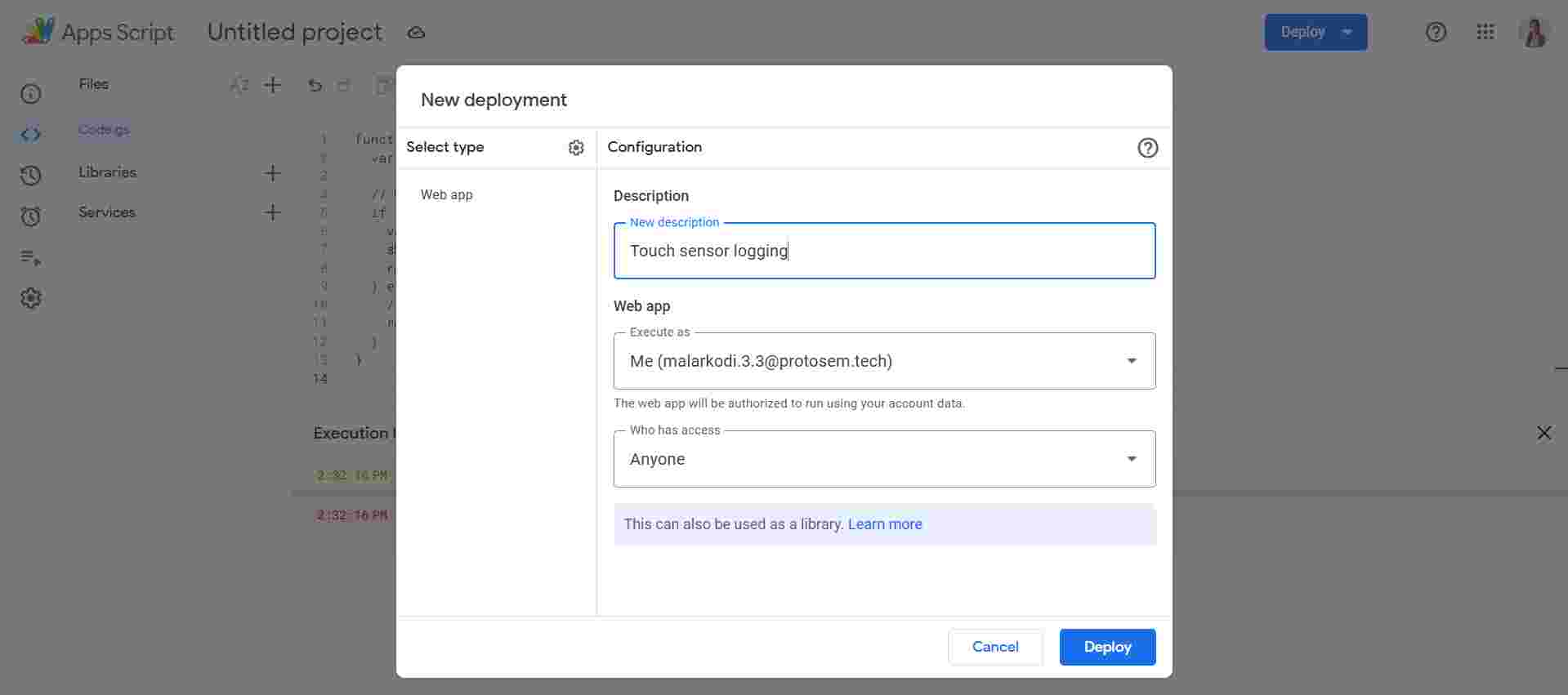
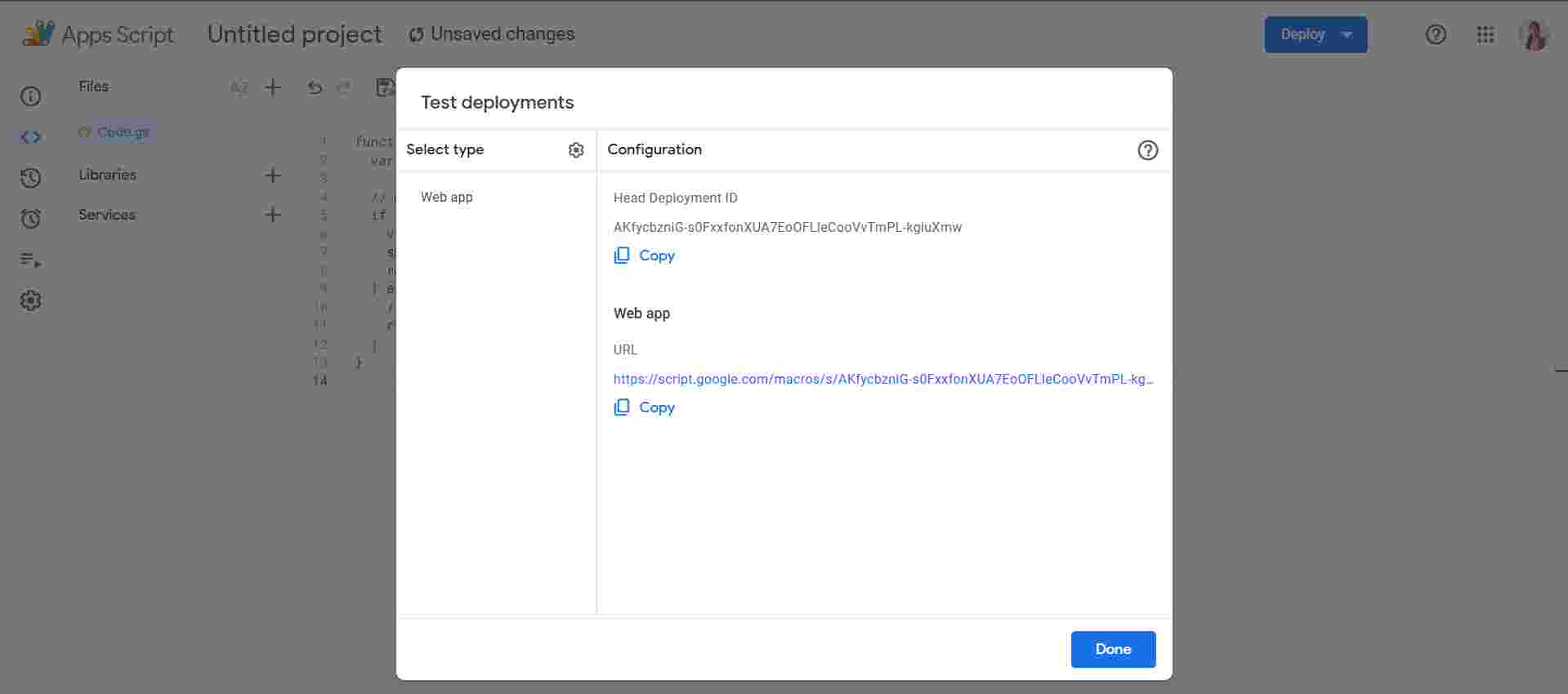
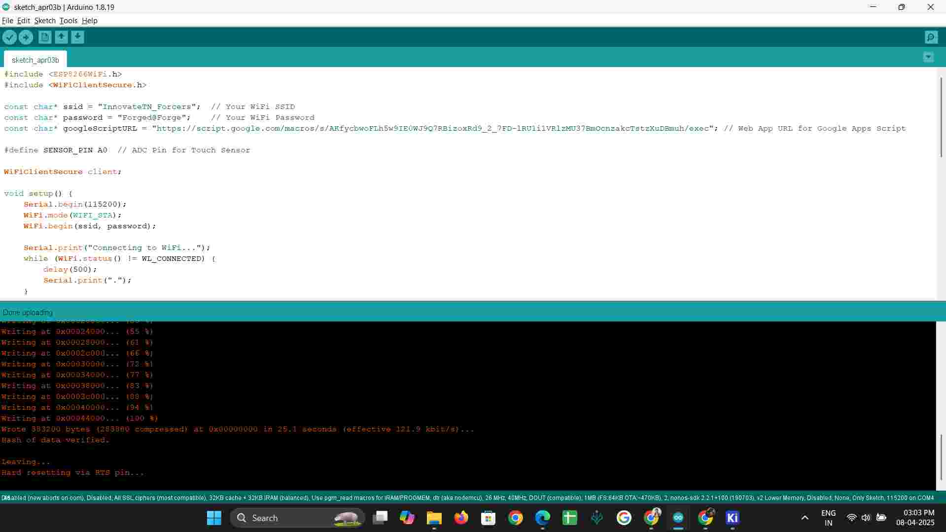
3. Arduino Code to Send Data to Google Sheets
#include <ESP8266WiFi.h>
#include <WiFiClientSecure.h>
const char* ssid = "InnovateTN_Forcers"; // Your WiFi SSID
const char* password = "Forged@Forge"; // Your WiFi Password
const char* googleScriptURL =
"https://script.google.com/macros/s/AKfycbwoFLh5w9IE0WJ9Q7RBizoxRd9_2_7FD-lRU1i1VRlzMU37B
mOcnzakcTstzXuDBmuh/exec"; // Web App URL for Google Apps Script
#define SENSOR_PIN A0 // ADC Pin for Touch Sensor
WiFiClientSecure client;
void setup() {
Serial.begin(115200);
WiFi.mode(WIFI_STA);
WiFi.begin(ssid, password);
Serial.print("Connecting to WiFi...");
while (WiFi.status() != WL_CONNECTED) {
delay(500);
Serial.print(".");
}
Serial.println("\nWiFi Connected!");
// Disable SSL certificate verification for easier connection
client.setInsecure();
}
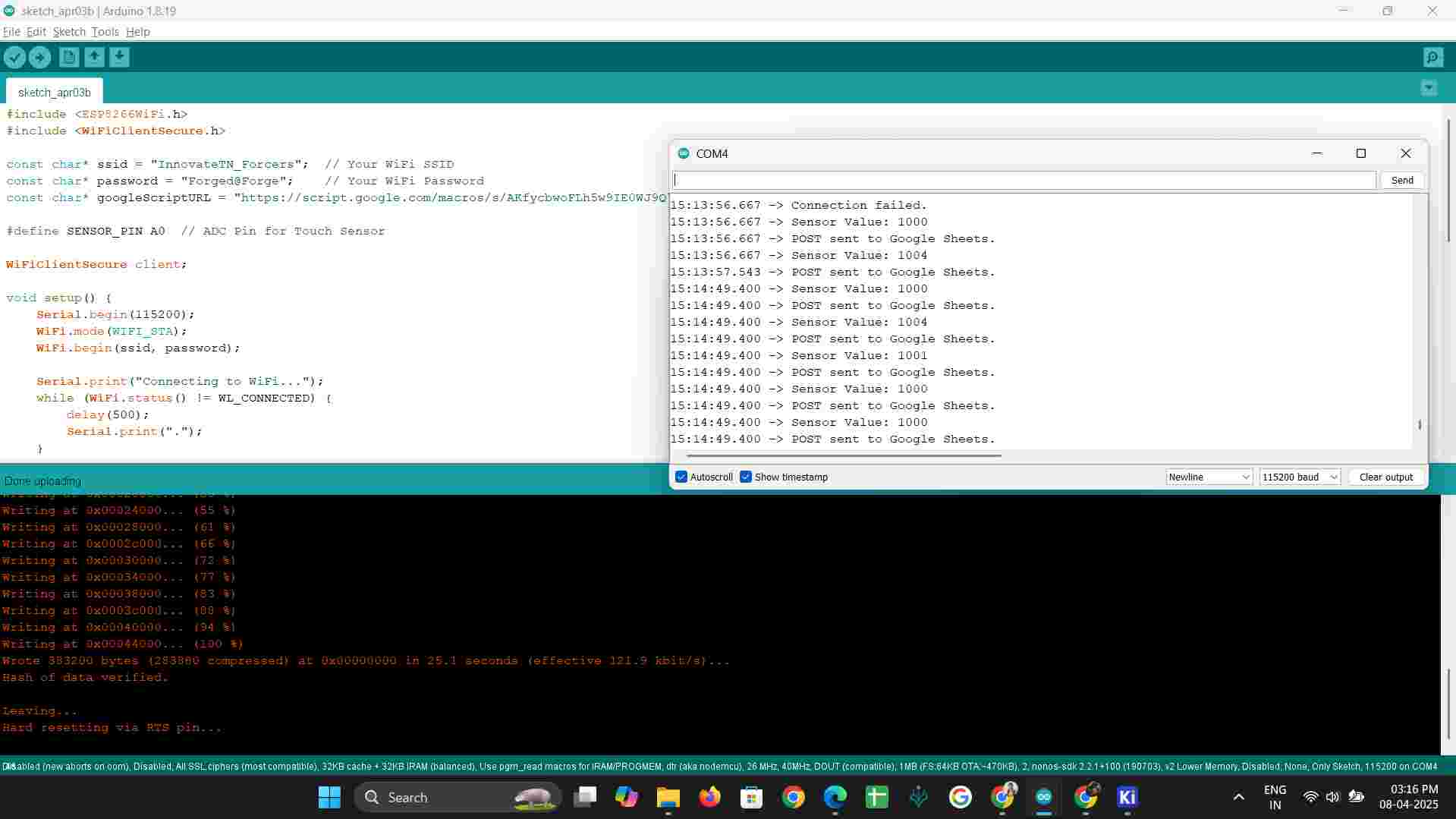
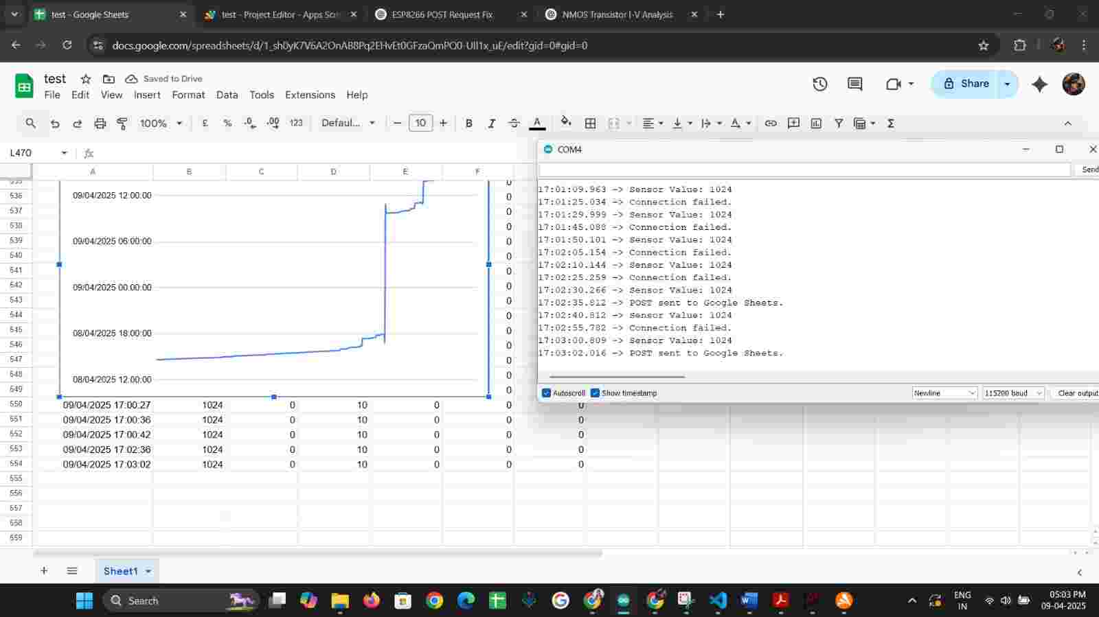
void loop() {
int sensorValue = analogRead(SENSOR_PIN); // Read the sensor value from ADC pin
Serial.print("Sensor Value: ");
Serial.println(sensorValue);
// Send the sensor data to Google Sheets
sendToGoogleSheets(sensorValue);
delay(5000); // Send data every 5 seconds
}
void sendToGoogleSheets(int value) {
if (client.connect("script.google.com", 443)) {
String payload = "{\"accX\":" + String(value) +
",\"accY\":0,\"accZ\":10,\"gyroX\":0,\"gyroY\":0,\"gyroZ\":0}";
String url =
"/macros/s/AKfycbwoFLh5w9IE0WJ9Q7RBizoxRd9_2_7FD-lRU1i1VRlzMU37BmOcnzakcTstzXuDBmuh/
exec";
client.println("POST " + url + " HTTP/1.1");
client.println("Host: script.google.com");
client.println("Content-Type: application/json");
client.println("Content-Length: " + String(payload.length()));
client.println();
client.println(payload);
Serial.println("POST sent to Google Sheets.");
} else {
Serial.println("Connection failed.");
}
}
REFERENCE LINK
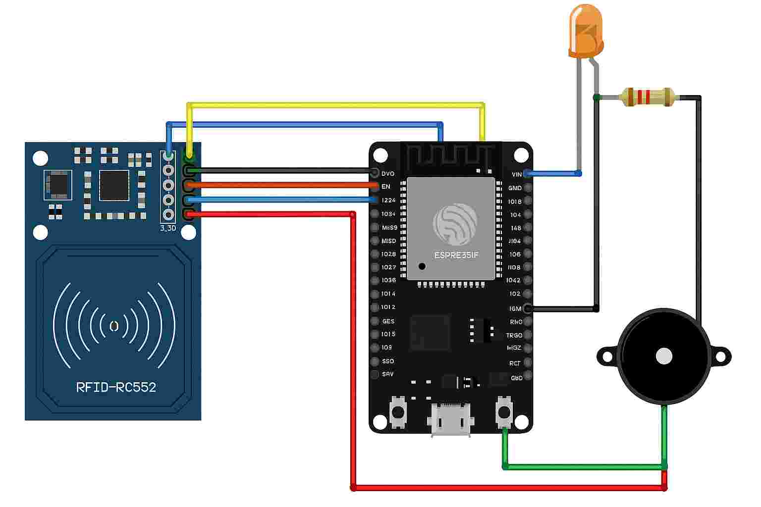
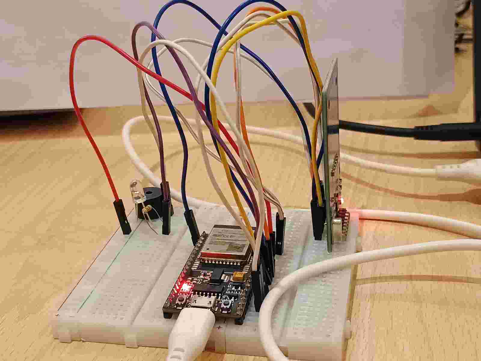
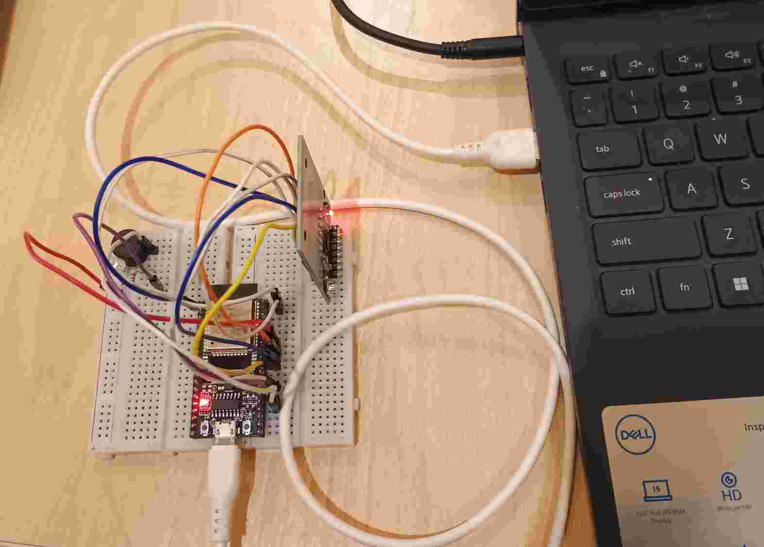
ESP32 RFID Logger
RC522 Pin | ESP32 Pin |
SDA | GPIO5 |
SCK | GPIO18 |
MOSI | GPIO23 |
MISO | GPIO19 |
RST | GPIO4 |
VCC | 3.3V |
GND | GND |
CODE:
#include <SPI.h>
#include <MFRC522.h>
#define SS_PIN 5
#define RST_PIN 4
#define LED_PIN 2
#define BUZZER_PIN 15
MFRC522 mfrc522(SS_PIN, RST_PIN);
byte validUID[4] = {0xDE, 0xAD, 0xBE, 0xEF};
void setup() {
Serial.begin(115200);
SPI.begin(); mfrc522.PCD_Init();
pinMode(LED_PIN, OUTPUT);
pinMode(BUZZER_PIN, OUTPUT); }
void loop() {
if (!mfrc522.PICC_IsNewCardPresent() || !mfrc522.PICC_ReadCardSerial())
{ return; }
if (isUIDMatch(mfrc522.uid.uidByte, validUID)) { blinkAndBeep(LED_PIN, BUZZER_PIN, 1, 200);
Serial.println("Valid User"); } else { blinkAndBeep(LED_PIN, BUZZER_PIN, 3, 200);
Serial.println("Unknown User"); }
mfrc522.PICC_HaltA(); }
bool isUIDMatch(byte *a, byte *b) {
for (byte i = 0; i < 4; i++) {
if (a[i] != b[i]) return false; } return true; }
void blinkAndBeep(int ledPin, int buzzerPin, int times, int delayTime) {
for (int i = 0; i < times; i++) {
digitalWrite(ledPin, HIGH);
digitalWrite(buzzerPin, HIGH);
delay(delayTime); digitalWrite(ledPin, LOW);
digitalWrite(buzzerPin, LOW);
delay(delayTime); } }
REFERENCE LINK
To replace that dummy UID with your actual RFID tag’s UID, follow these steps:
1. Read your tag’s UID:
Upload this minimal sketch to your ESP32:
#include <SPI.h>
#include <MFRC522.h>
#define SS_PIN 5 // SDA pin (connect to D5 on ESP32 or pin 10 on Arduino Uno)
#define RST_PIN 4 // RST pin (connect to D4 on ESP32 or pin 9 on Arduino Uno)
MFRC522 mfrc522(SS_PIN, RST_PIN); // Create MFRC522 instance
void setup() {
Serial.begin(115200); // Start serial communication
SPI.begin(); // Init SPI bus
mfrc522.PCD_Init(); // Init MFRC522
Serial.println("Scan your card...");
}
void loop() {
// Look for a new card
if (!mfrc522.PICC_IsNewCardPresent() || !mfrc522.PICC_ReadCardSerial()) {
return;
}
// Show UID
Serial.print("UID: ");
for (byte i = 0; i < mfrc522.uid.size; i++) {
Serial.print("0x");
if (mfrc522.uid.uidByte[i] < 0x10) {
Serial.print("0");
}
Serial.print(mfrc522.uid.uidByte[i], HEX);
Serial.print(" ");
}
Serial.println();
delay(1000); // Add delay to avoid flooding the output
}
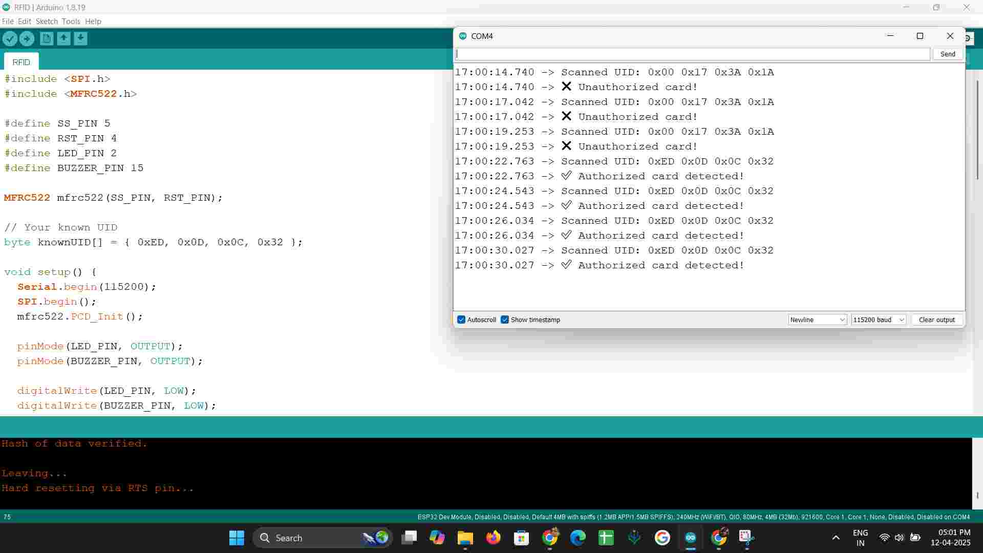
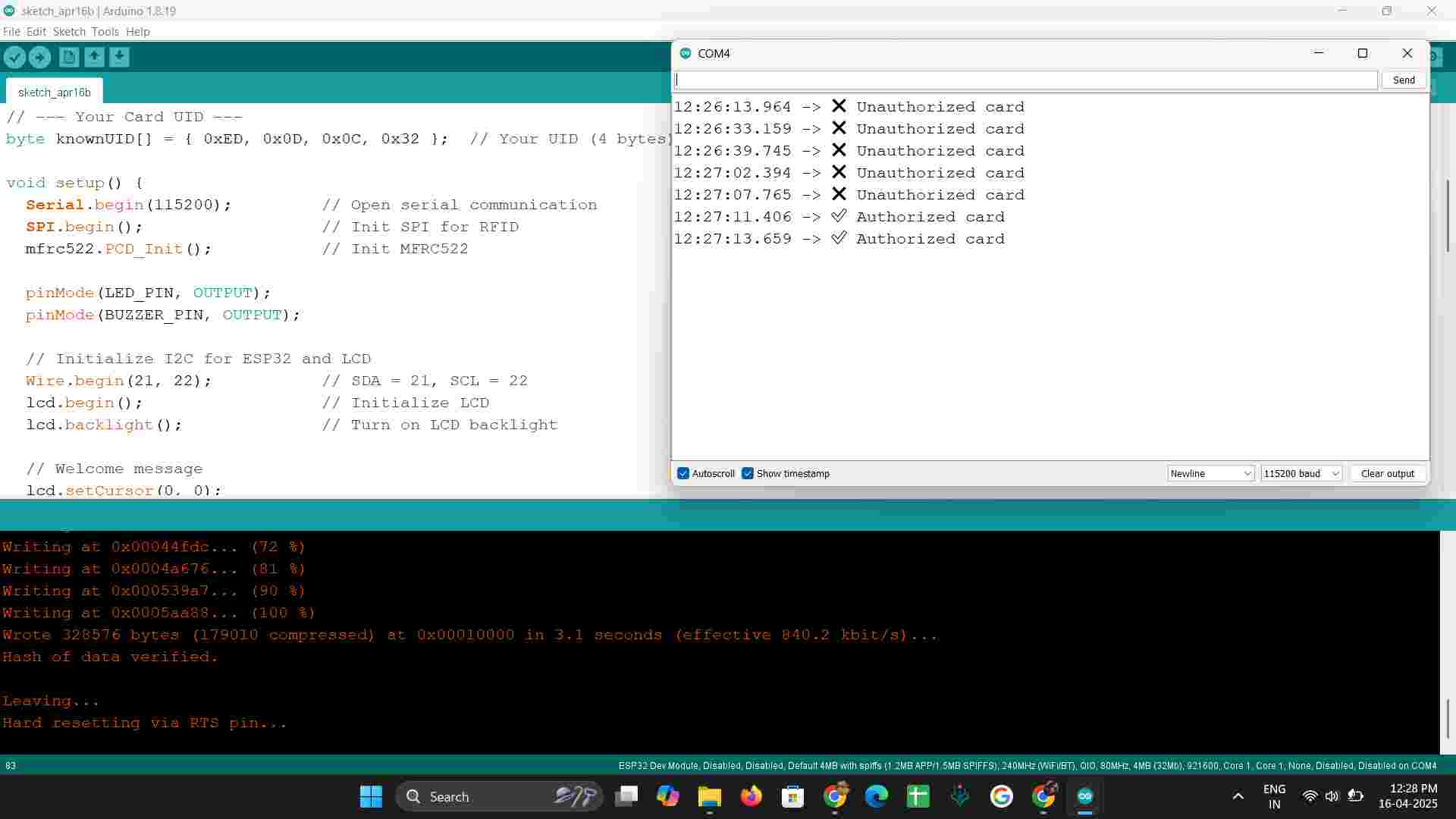
Open the Serial Monitor (set to 115200 baud), then scan your RFID tag. You’ll see something like:
UID: 0xA1, 0xB2, 0xC3, 0xD4
REFERENCE LINK
#include <SPI.h>
#include <MFRC522.h>
#define SS_PIN 5
#define RST_PIN 4
#define LED_PIN 2
#define BUZZER_PIN 15
MFRC522 mfrc522(SS_PIN, RST_PIN);
// Your known UID
byte knownUID[] = { 0xED, 0x0D, 0x0C, 0x32 };
void setup() {
Serial.begin(115200);
SPI.begin();
mfrc522.PCD_Init();
pinMode(LED_PIN, OUTPUT);
pinMode(BUZZER_PIN, OUTPUT);
digitalWrite(LED_PIN, LOW);
digitalWrite(BUZZER_PIN, LOW);
Serial.println("Scan your card...");
}
void loop() {
if (!mfrc522.PICC_IsNewCardPresent() || !mfrc522.PICC_ReadCardSerial()) {
return;
}
Serial.print("Scanned UID: ");
bool match = true;
for (byte i = 0; i < mfrc522.uid.size; i++) {
Serial.print("0x");
if (mfrc522.uid.uidByte[i] < 0x10) Serial.print("0");
Serial.print(mfrc522.uid.uidByte[i], HEX);
Serial.print(" ");
if (mfrc522.uid.uidByte[i] != knownUID[i]) {
match = false;
}
}
Serial.println();
if (match) {
Serial.println("✅ Authorized card detected!");
digitalWrite(LED_PIN, HIGH);
digitalWrite(BUZZER_PIN, HIGH);
delay(500); // 0.5 sec ON
digitalWrite(LED_PIN, LOW);
digitalWrite(BUZZER_PIN, LOW);
} else {
Serial.println("❌ Unauthorized card!");
for (int i = 0; i < 3; i++) {
digitalWrite(LED_PIN, HIGH);
digitalWrite(BUZZER_PIN, HIGH);
delay(200);
digitalWrite(LED_PIN, LOW);
digitalWrite(BUZZER_PIN, LOW);
delay(200);
}
}
// Halt PICC and stop encryption
mfrc522.PICC_HaltA();
mfrc522.PCD_StopCrypto1();
delay(1000); // Pause before next scan
}
REFERENCE LINK
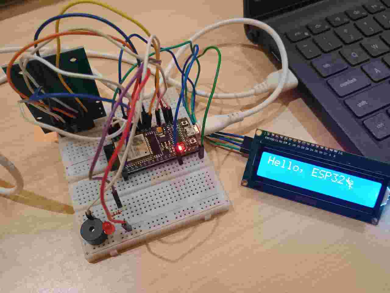
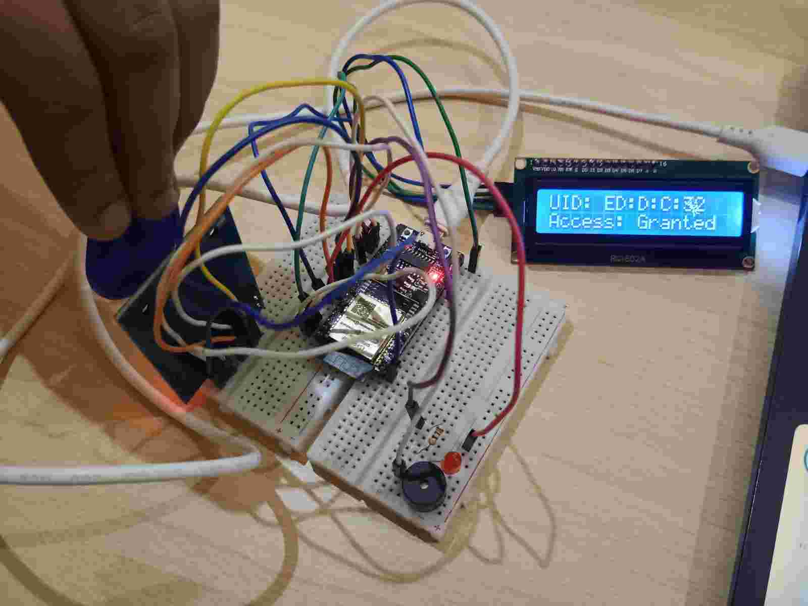
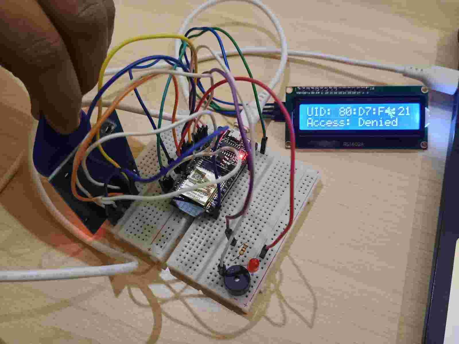
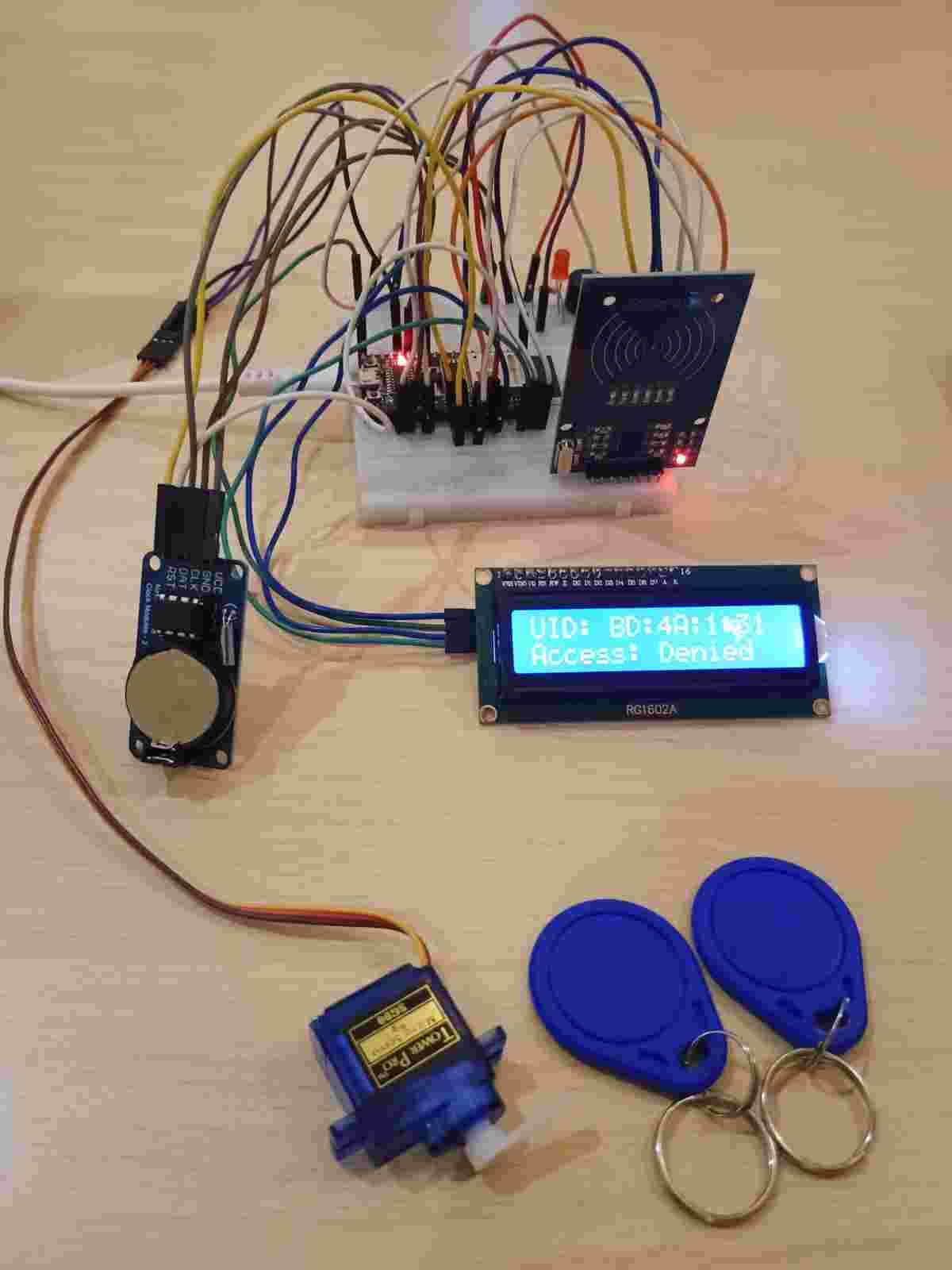
INTERFACE WITH LCD DISPLAY
Interfacing LCD with ESP32 (ESP32-WROOM-32E)
LCD Pin | Connect to ESP32 Pin |
VCC | 3.3V or 5V |
GND | GND |
SDA | GPIO21 |
SCL | GPIO22 |
Important: ESP32’s default I2C pins are:
Search for:
LiquidCrystal I2C
Before using the LCD, run this sketch to detect its I2C address:
#include <Wire.h>
void setup() {
Wire.begin(21, 22); // SDA = 21, SCL = 22 for ESP32
Serial.begin(9600);
Serial.println("I2C Scanner Running...");
}
void loop() {
byte error, address;
for (address = 1; address < 127; address++) {
Wire.beginTransmission(address);
error = Wire.endTransmission();
if (error == 0) {
Serial.print("I2C device found at 0x");
if (address < 16) Serial.print("0");
Serial.println(address, HEX);
}
}
delay(5000);
}
#include <Wire.h>
#include <LiquidCrystal_I2C.h>
// Replace 0x27 with the address from your I2C scanner
LiquidCrystal_I2C lcd(0x27, 16, 2);
void setup() {
Wire.begin(21, 22); // ESP32 I2C pins
Serial.begin(9600);
lcd.begin(); // For some libraries use lcd.init();
lcd.backlight();
lcd.setCursor(0, 0);
lcd.print("Hello, ESP32!");
}
void loop() {
Serial.println("hello esp32");
delay(1000); // Add delay to prevent serial flooding
}
#include <Wire.h>
#include <LiquidCrystal_I2C.h>
#include <SPI.h>
#include <MFRC522.h>
// --- Pin Definitions ---
#define SS_PIN 5 // RFID SS (SDA)
#define RST_PIN 4 // RFID RST
#define LED_PIN 2 // On-board LED
#define BUZZER_PIN 15 // Buzzer pin
// --- Initialize RFID and LCD ---
LiquidCrystal_I2C lcd(0x27, 16, 2); // LCD at I2C address 0x27
MFRC522 mfrc522(SS_PIN, RST_PIN); // RFID module
// --- Your Card UID ---
byte knownUID[] = { 0xED, 0x0D, 0x0C, 0x32 }; // Your UID (4 bytes)
void setup() {
Serial.begin(115200); // Open serial communication
SPI.begin(); // Init SPI for RFID
mfrc522.PCD_Init(); // Init MFRC522
pinMode(LED_PIN, OUTPUT);
pinMode(BUZZER_PIN, OUTPUT);
// Initialize I2C for ESP32 and LCD
Wire.begin(21, 22); // SDA = 21, SCL = 22
lcd.begin(); // Initialize LCD
lcd.backlight(); // Turn on LCD backlight
// Welcome message
lcd.setCursor(0, 0);
lcd.print("Scan your card");
}
void loop() {
// Wait for a new card
if (!mfrc522.PICC_IsNewCardPresent() || !mfrc522.PICC_ReadCardSerial()) {
return;
}
bool match = true;
lcd.clear();
lcd.setCursor(0, 0);
lcd.print("UID: ");
// Display UID & compare
for (byte i = 0; i < mfrc522.uid.size; i++) {
lcd.print(mfrc522.uid.uidByte[i], HEX);
if (i < mfrc522.uid.size - 1) lcd.print(":");
if (mfrc522.uid.uidByte[i] != knownUID[i]) {
match = false;
}
}
lcd.setCursor(0, 1);
if (match) {
Serial.println("✅ Authorized card");
lcd.print("Access: Granted");
digitalWrite(LED_PIN, HIGH);
digitalWrite(BUZZER_PIN, HIGH);
delay(500);
digitalWrite(LED_PIN, LOW);
digitalWrite(BUZZER_PIN, LOW);
} else {
Serial.println("❌ Unauthorized card");
lcd.print("Access: Denied");
for (int i = 0; i < 3; i++) {
digitalWrite(LED_PIN, HIGH);
digitalWrite(BUZZER_PIN, HIGH);
delay(200);
digitalWrite(LED_PIN, LOW);
digitalWrite(BUZZER_PIN, LOW);
delay(200);
}
}
// End communication with current card
mfrc522.PICC_HaltA();
mfrc522.PCD_StopCrypto1();
delay(1000); // Pause before next scan
}
REFERENCE LINK:
WhatsApp Video 2025-04-16 at 12.28.09 PM.mp4
Connections
Servo Wire | Connects to |
Orange (Signal) | GPIO 13 of ESP32 |
Red (VCC) | 5V (External Power Supply) |
Brown (GND) | Common GND with ESP32 & Power Supply |
Install via Library Manager:
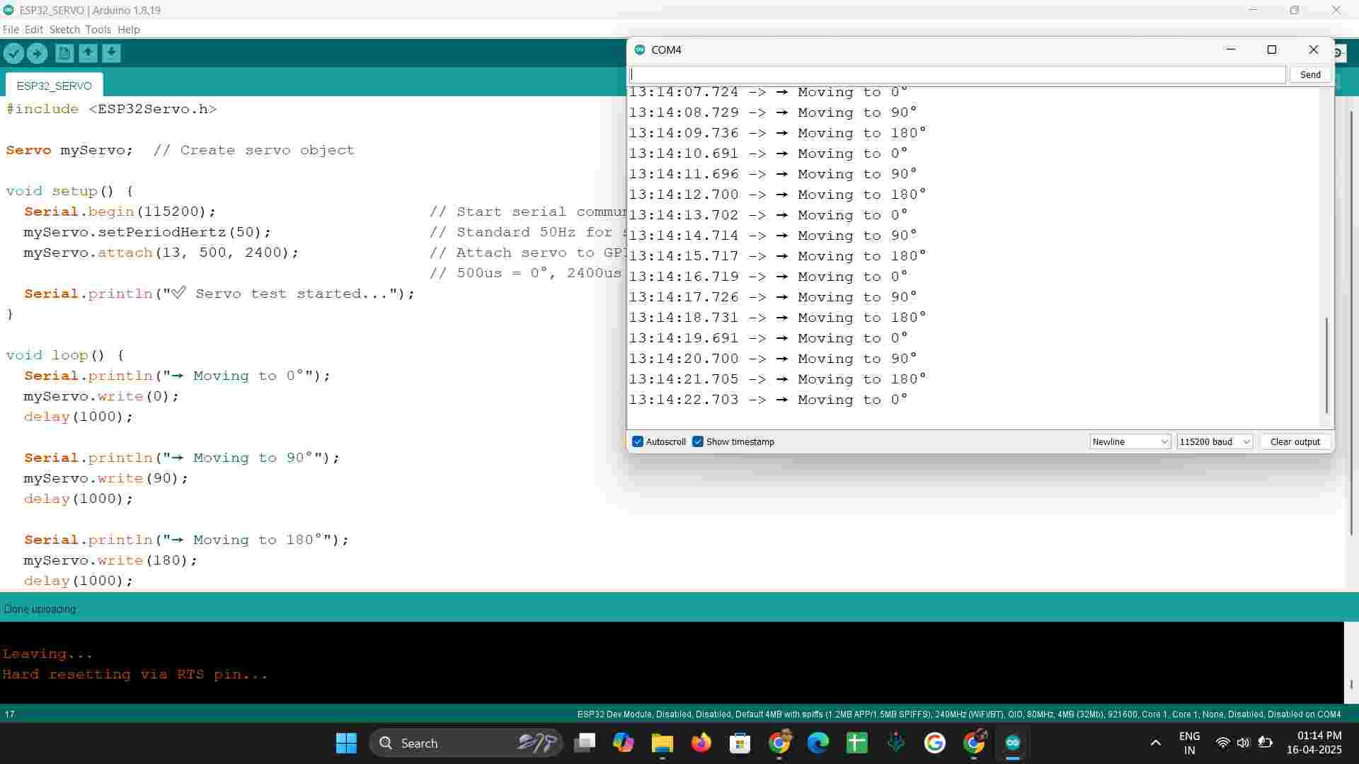
ESP32Servo by Kevin Harrington
#include <ESP32Servo.h>
Servo myServo; // Create servo object
void setup() {
Serial.begin(115200); // Start serial communication
myServo.setPeriodHertz(50); // Standard 50Hz for servo
myServo.attach(13, 500, 2400); // Attach servo to GPIO 13
// 500us = 0°, 2400us = 180°
Serial.println("✅ Servo test started...");
}
void loop() {
Serial.println("→ Moving to 0°");
myServo.write(0);
delay(1000);
Serial.println("→ Moving to 90°");
myServo.write(90);
delay(1000);
Serial.println("→ Moving to 180°");
myServo.write(180);
delay(1000);
}
Function | Description |
setPeriodHertz(50) | Sets PWM frequency (50 Hz typical for servo motors) |
attach(pin, min, max) | Attaches servo to GPIO pin with pulse limits |
write(angle) | Rotates servo to specified angle (0–180°) |
OUTPUT:
REFERENCE LINK
WhatsApp Video 2025-04-16 at 1.24.08 PM.mp4
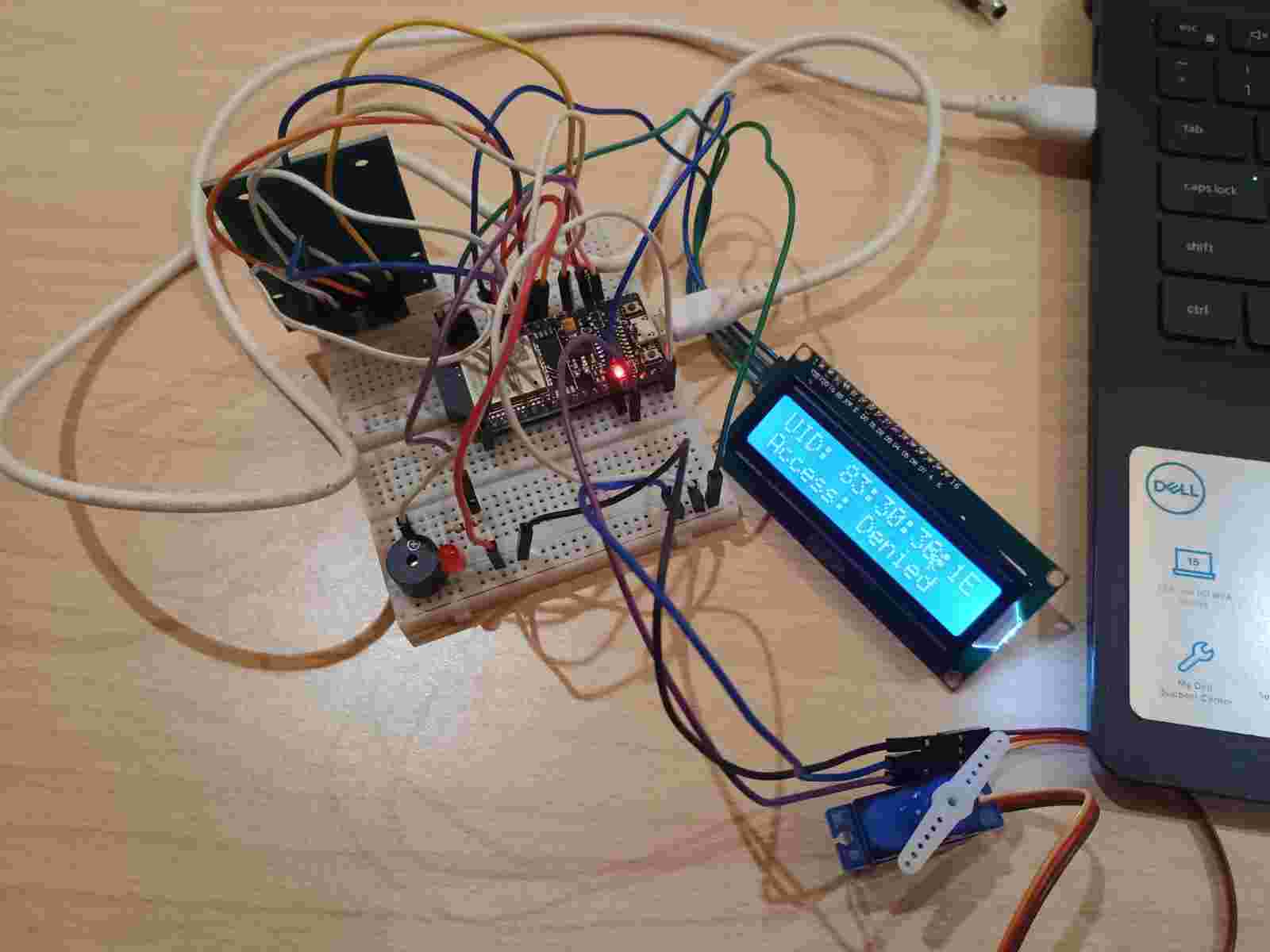
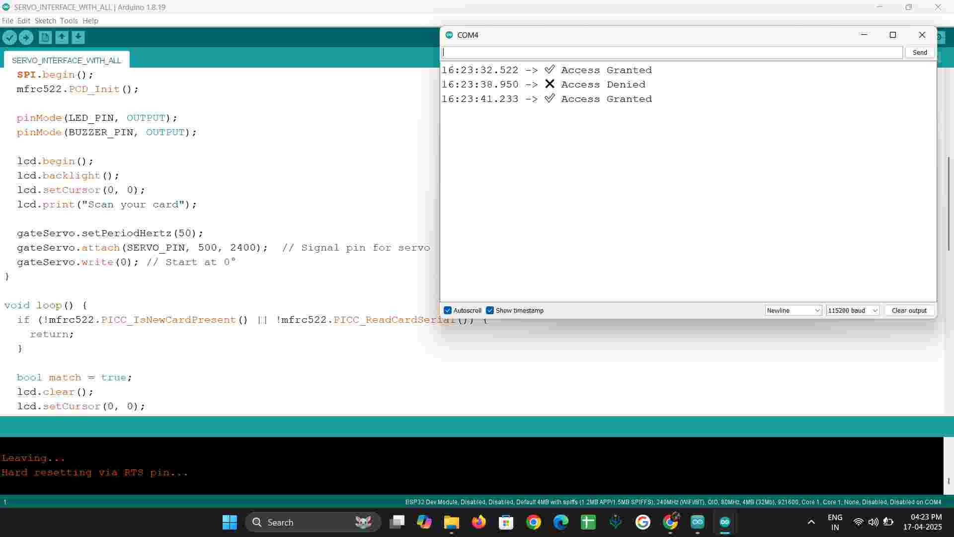
SERVO INTERFACE WITH ALL
OUTPUT
REFERENCE LINK
WhatsApp Video 2025-04-17 at 4.22.46 PM.mp4
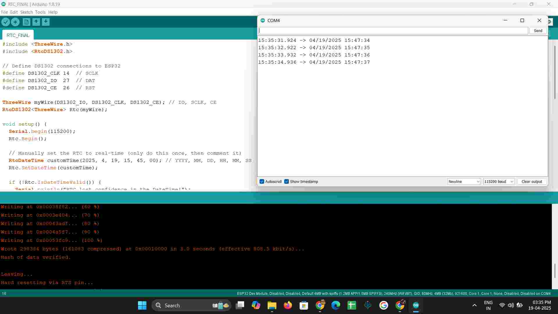
ESP WITH RTC MODULE
DS1302 Pin | ESP32 Pin | Description |
VCC | 3.3V | Power supply |
GND | GND | Ground |
CLK | GPIO14 | Clock |
DAT | GPIO19 | Data I/O |
RST | GPIO5 | Chip Enable (CE) |
Make sure a CR2032 battery is inserted into your RTC module for backup.
If not installed already:
Working Code: DS1302 + ESP32
#include <ThreeWire.h>
#include <RtcDS1302.h>
// Define DS1302 connections to ESP32
#define DS1302_CLK 14 // SCLK
#define DS1302_IO 27 // DAT
#define DS1302_CE 26 // RST
ThreeWire myWire(DS1302_IO, DS1302_CLK, DS1302_CE); // IO, SCLK, CE
RtcDS1302<ThreeWire> Rtc(myWire);
void setup() {
Serial.begin(115200);
Rtc.Begin();
// Manually set the RTC to real-time (only do this once, then comment it)
RtcDateTime customTime(2025, 4, 19, 15, 45, 00); // YYYY, MM, DD, HH, MM, SS
Rtc.SetDateTime(customTime);
if (!Rtc.IsDateTimeValid()) {
Serial.println("RTC lost confidence in the DateTime!");
}
if (!Rtc.GetIsRunning()) {
Serial.println("RTC was not running. Starting it now...");
Rtc.SetIsRunning(true);
}
// Print initial time
RtcDateTime now = Rtc.GetDateTime();
printDateTime(now);
}
void loop() {
RtcDateTime now = Rtc.GetDateTime();
printDateTime(now);
delay(1000);
}
void printDateTime(const RtcDateTime& dt) {
char datestring[20];
snprintf_P(datestring,
sizeof(datestring),
PSTR("%02u/%02u/%04u %02u:%02u:%02u"),
dt.Month(),
dt.Day(),
dt.Year(),
dt.Hour(),
dt.Minute(),
dt.Second());
Serial.println(datestring);
}
OUTPUT:
REFERENCE LINK
WhatsApp Video 2025-04-19 at 1.42.37 PM.mp4
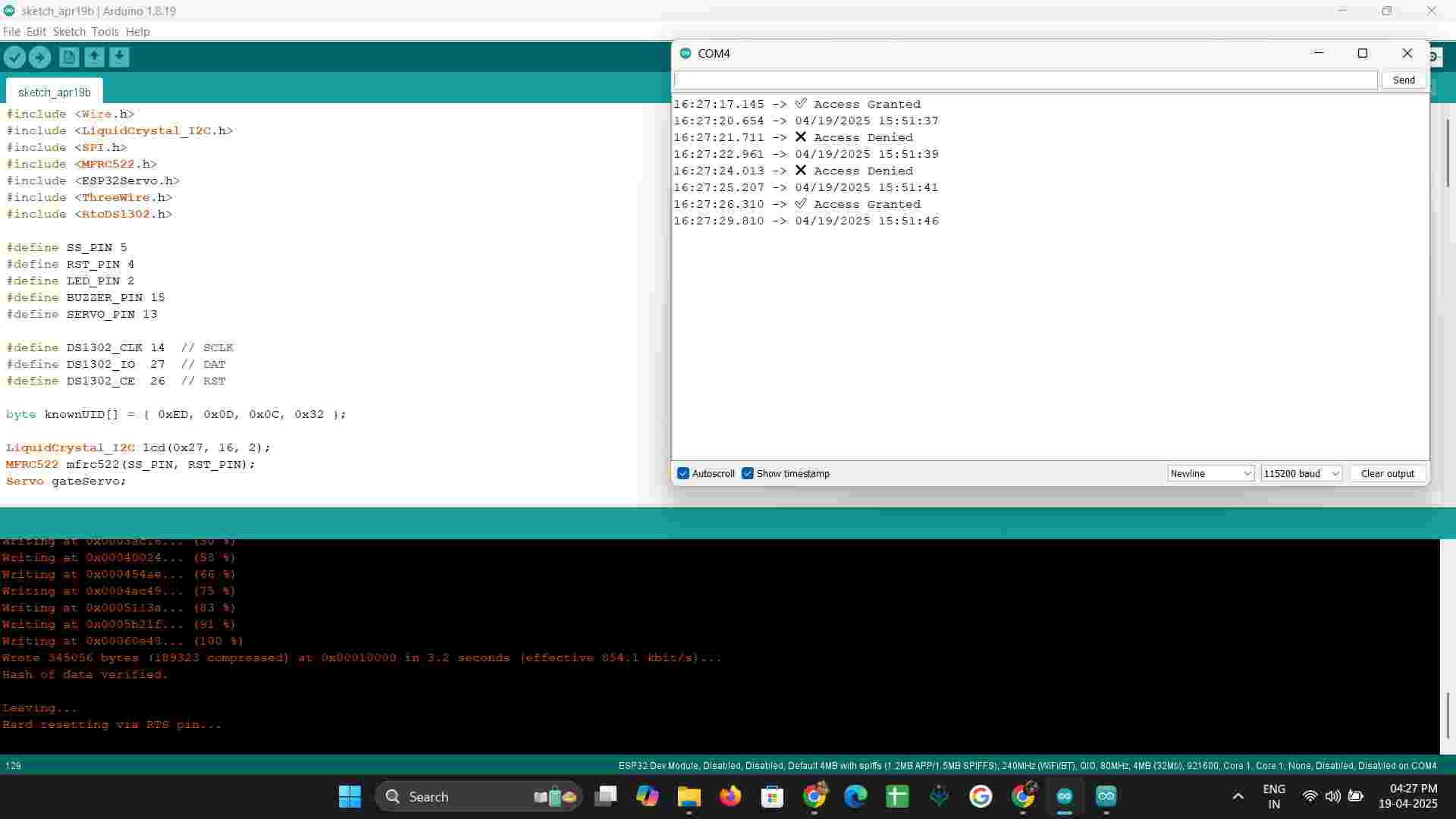
INTERFACE WITH ALL:
Code:
#include <Wire.h>
#include <LiquidCrystal_I2C.h>
#include <SPI.h>
#include <MFRC522.h>
#include <ESP32Servo.h>
#include <ThreeWire.h>
#include <RtcDS1302.h>
#define SS_PIN 5
#define RST_PIN 4
#define LED_PIN 2
#define BUZZER_PIN 15
#define SERVO_PIN 13
#define DS1302_CLK 14 // SCLK
#define DS1302_IO 27 // DAT
#define DS1302_CE 26 // RST
byte knownUID[] = { 0xED, 0x0D, 0x0C, 0x32 };
LiquidCrystal_I2C lcd(0x27, 16, 2);
MFRC522 mfrc522(SS_PIN, RST_PIN);
Servo gateServo;
ThreeWire myWire(DS1302_IO, DS1302_CLK, DS1302_CE); // IO, SCLK, CE
RtcDS1302<ThreeWire> Rtc(myWire);
void setup() {
Serial.begin(115200);
SPI.begin();
mfrc522.PCD_Init();
pinMode(LED_PIN, OUTPUT);
pinMode(BUZZER_PIN, OUTPUT);
lcd.begin();
lcd.backlight();
lcd.setCursor(0, 0);
lcd.print("Scan your card");
gateServo.setPeriodHertz(50);
gateServo.attach(SERVO_PIN, 500, 2400); // Signal pin for servo
gateServo.write(0); // Start at 0°
// RTC Setup
Rtc.Begin();
RtcDateTime customTime(2025, 4, 19, 15, 45, 00); // YYYY, MM, DD, HH, MM, SS
Rtc.SetDateTime(customTime);
if (!Rtc.IsDateTimeValid()) {
Serial.println("RTC lost confidence in the DateTime!");
}
if (!Rtc.GetIsRunning()) {
Serial.println("RTC was not running. Starting it now...");
Rtc.SetIsRunning(true);
}
// Print initial time
RtcDateTime now = Rtc.GetDateTime();
printDateTime(now);
}
void loop() {
if (!mfrc522.PICC_IsNewCardPresent() || !mfrc522.PICC_ReadCardSerial()) {
return;
}
bool match = true;
lcd.clear();
lcd.setCursor(0, 0);
lcd.print("UID: ");
for (byte i = 0; i < mfrc522.uid.size; i++) {
lcd.print(mfrc522.uid.uidByte[i], HEX);
if (i < mfrc522.uid.size - 1) lcd.print(":");
if (mfrc522.uid.uidByte[i] != knownUID[i]) match = false;
}
if (match) {
Serial.println("✅ Access Granted");
lcd.setCursor(0, 1);
lcd.print("Access: Granted");
digitalWrite(LED_PIN, HIGH);
digitalWrite(BUZZER_PIN, HIGH);
gateServo.write(180); // Open gate
delay(500);
digitalWrite(LED_PIN, LOW);
digitalWrite(BUZZER_PIN, LOW);
delay(3000);
gateServo.write(0); // Close gate
} else {
Serial.println("❌ Access Denied");
lcd.setCursor(0, 1);
lcd.print("Access: Denied");
for (int i = 0; i < 3; i++) {
digitalWrite(LED_PIN, HIGH);
digitalWrite(BUZZER_PIN, HIGH);
delay(200);
digitalWrite(LED_PIN, LOW);
digitalWrite(BUZZER_PIN, LOW);
delay(200);
}
gateServo.write(0); // Keep gate closed
}
// Get current time from RTC
RtcDateTime now = Rtc.GetDateTime();
printDateTime(now); // Print the current time from RTC
mfrc522.PICC_HaltA();
mfrc522.PCD_StopCrypto1();
delay(1000);
}
void printDateTime(const RtcDateTime& dt) {
char datestring[20];
snprintf_P(datestring,
sizeof(datestring),
PSTR("%02u/%02u/%04u %02u:%02u:%02u"),
dt.Month(),
dt.Day(),
dt.Year(),
dt.Hour(),
dt.Minute(),
dt.Second());
Serial.println(datestring);
}
Output:
REFERENCE LINK:
WhatsApp Video 2025-04-19 at 4.29.08 PM.mp4