Week 3
Computer-Controlled Cutting
Group assignment
do your lab's safety training
characterize your lasercutter's focus, power, speed, rate, kerf, joint clearance and types
The Link of Group assignments.
Individual assignment
- cut something on the vinylcutter
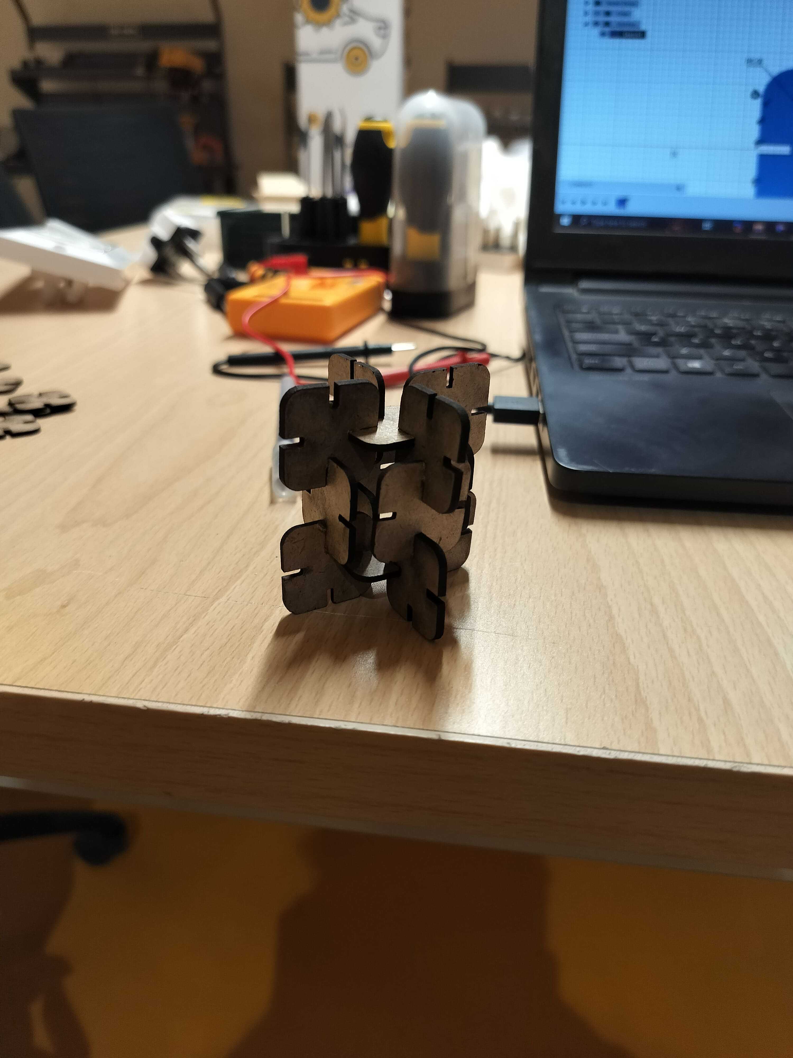
- design, lasercut, and document a parametric construction kit,
- accounting for the lasercutter kerf,
- which can be assembled in multiple ways,
- and for extra credit include elements that aren't flat
Introduction
Laser Cutting
This week, I am excited to dive into computer-controlled cutting for the first time! I've never worked with these machines before, so learning how to operate a laser cutter and a vinyl cutter is a thrilling experience.
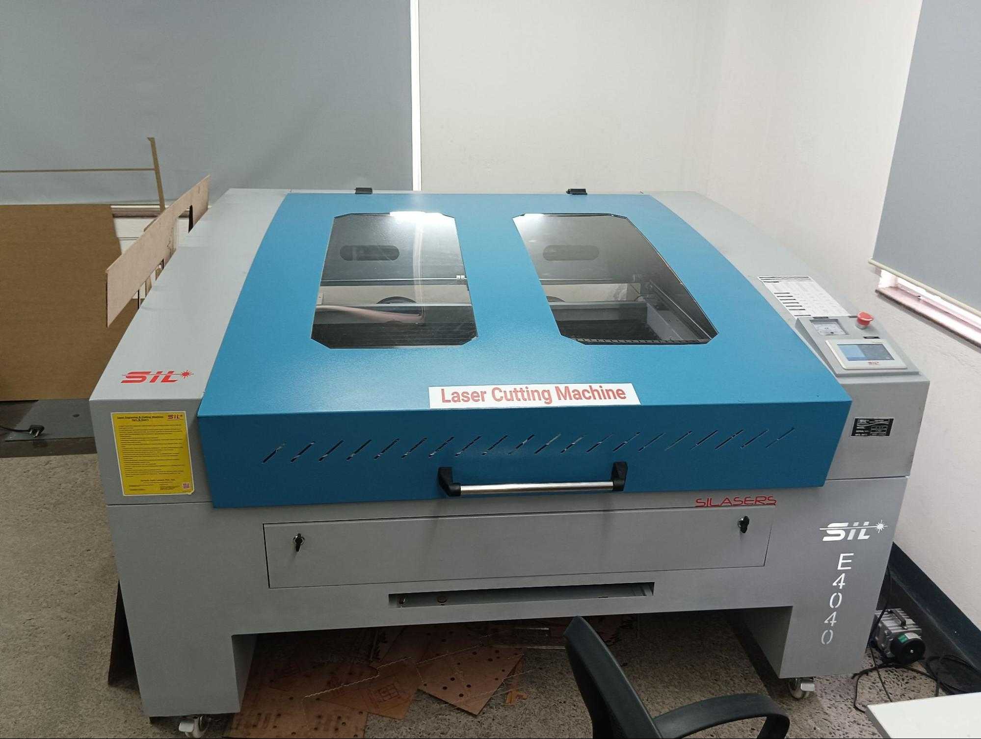
I'll be exploring the 100W SIL Acrylic Laser Cutting Machine, understanding its capabilities, and getting hands-on practice. Looking forward to mastering these tools and bringing my ideas to life!
Key Features:
- Laser Power: 100W CO₂ Laser
- Cutting Area: 1600 mm x 1000 mm
- Cutting Speed: 0–30 m/min | Engraving Speed: 0–64 m/min
- Accuracy: ±0.01 mm
- Supported Files: CorelDRAW, AutoCAD, Photoshop
1.Parametric design
i. Designing in Fusion 360
I started by using Fusion 360, a powerful CAD software, to create a parametric design. The parametric approach allows for easy modifications by defining constraints and dimensions rather than manually adjusting each element.
Visit fusion-360 Official Website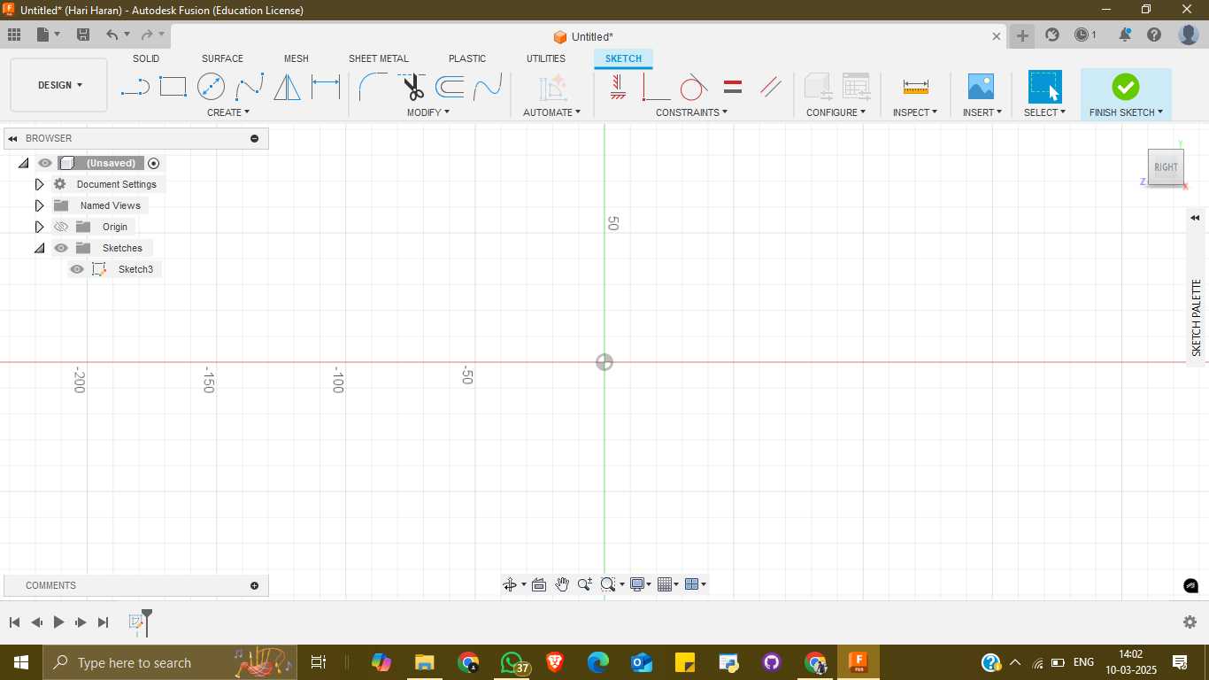
Parametric Design Explanation
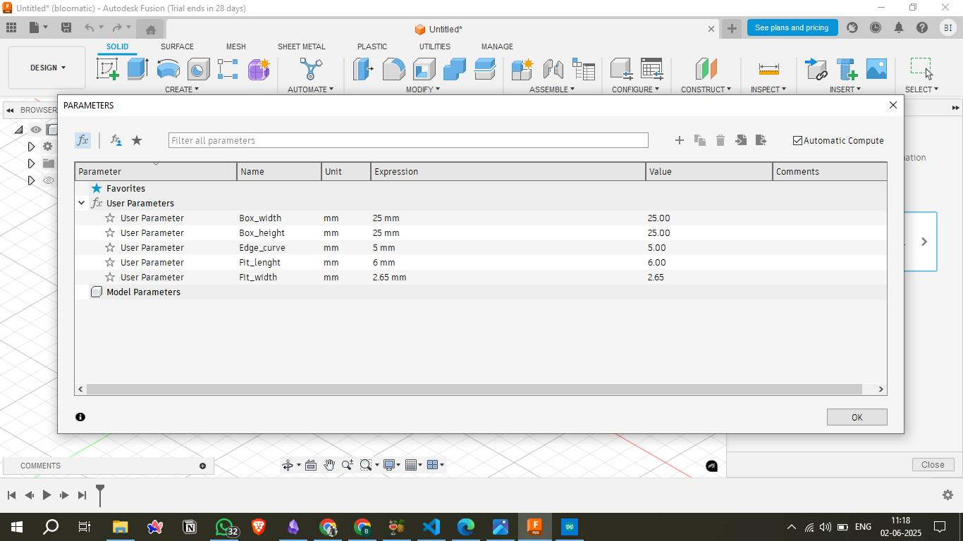
In this design, I utilized a parametric modeling approach in Autodesk Fusion 360. This method allows me to define key dimensions using user parameters, which can be adjusted easily to dynamically update the entire model without manually editing individual features. Below are the user-defined parameters and their roles in the design:
Design Parameters
- Box_width (25mm): Sets the width of the box. Changing this alters the horizontal size of the overall structure.
- Box_height (25mm): Sets the height of the box. Affects the vertical dimension of the design.
- Edge_curve (5mm): Determines the fillet or roundness at the edges of the box. Increasing this smoothens corners more.
- Fit_length (6mm): Controls how deep or long an internal fitting section is, possibly for joinery or mechanical fit.
- Fit_width (2.65mm): Specifies the width of the fit or notch area, ensuring proper alignment or interlocking parts.
Benefits of Parametric Modeling
Using parametric modeling simplifies future design updates. For instance, if I want a larger or smaller box, I only need to change Box_width and Box_height, and the entire design will adjust accordingly. This makes the design flexible, scalable, and easier to iterate.
ii. Sketching
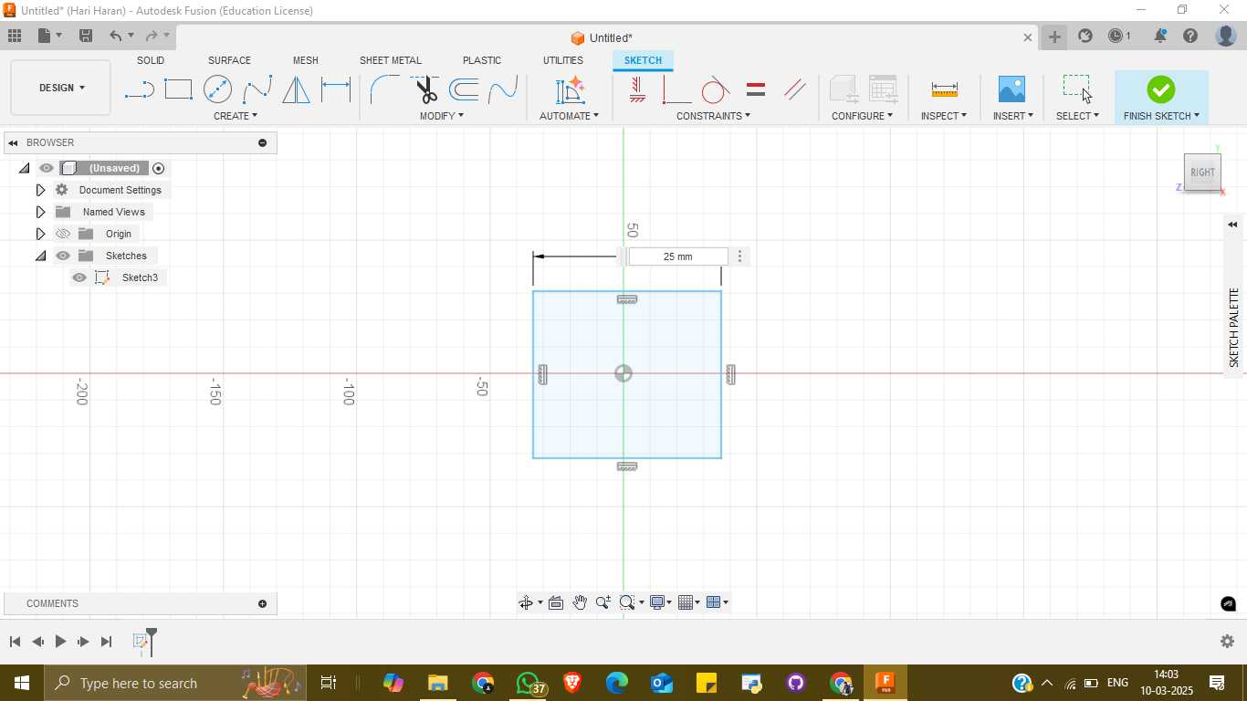
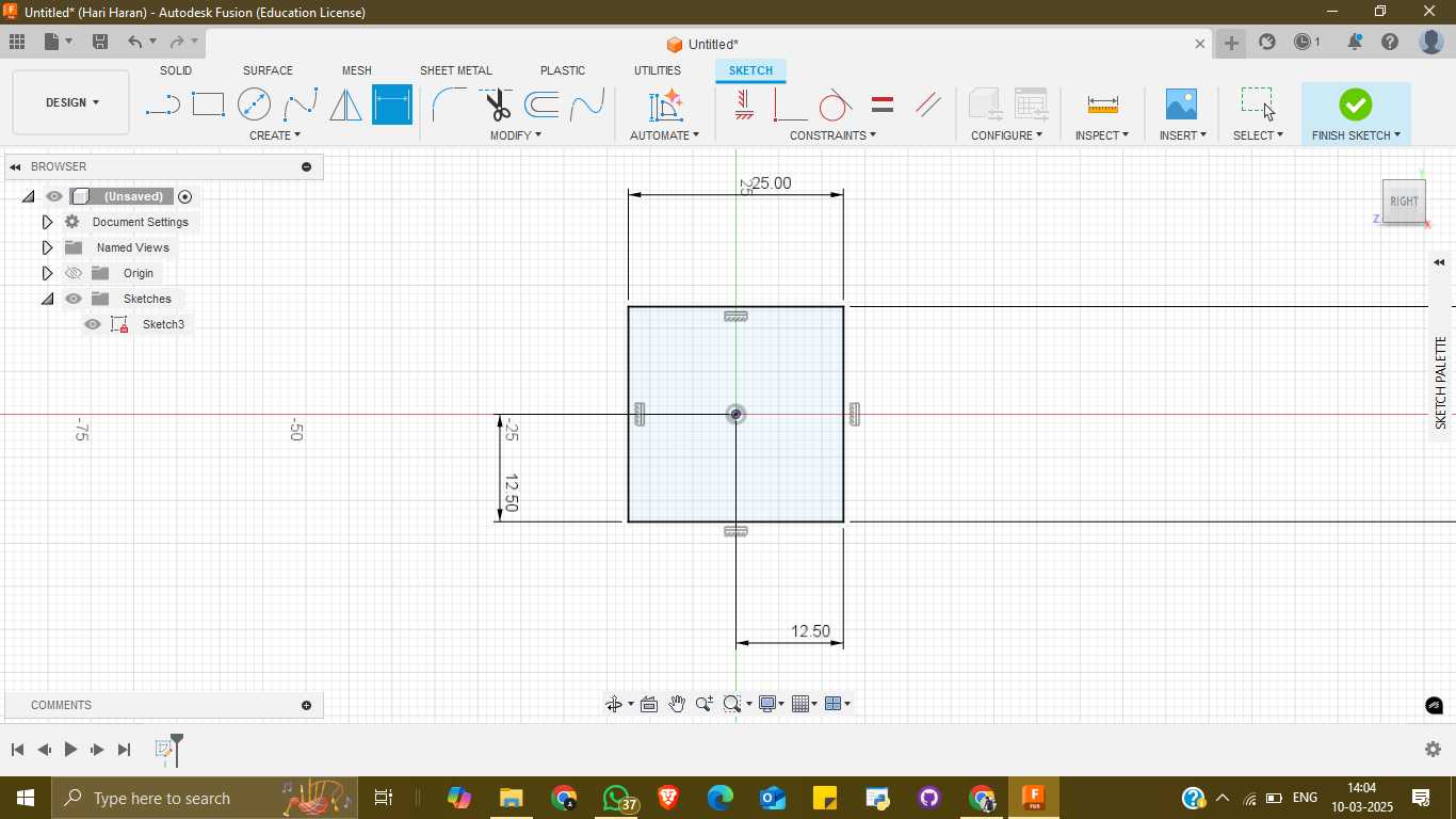
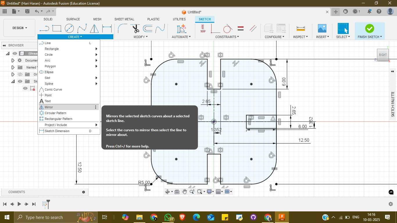
Using the Sketch tool, I designed a 25 mm × 25 mm square with curved corners to ensure a smooth and aesthetically pleasing shape. The board thickness is set to 2 mm, keeping the design compact and efficient.
iii. Creating the Snap-Fit Cutouts
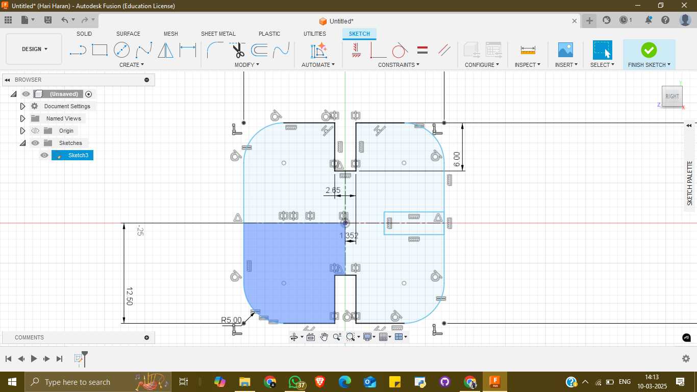
To achieve a tight snap-fit mechanism, I incorporated cut areas on all four sides, each with a width of 2.2 mm. This ensures a snug fit, allowing the parts to securely interlock while considering slight tolerances for manufacturing precision.
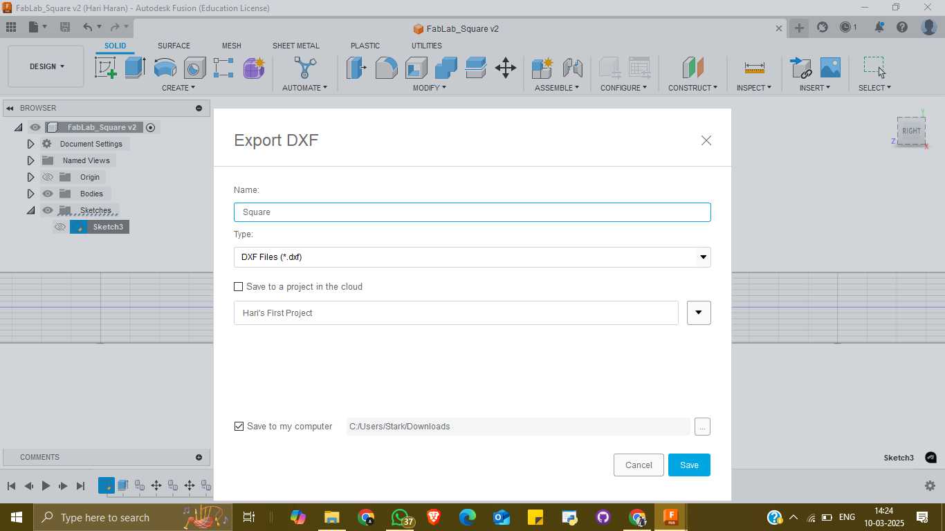
iv. Exporting for Fabrication
Once the design was finalized, I exported the file in DXF ( Drawing Exchange Format ) format, making it compatible with laser cutting machines. This ensures precise cutting and accurate assembly of the snap-fit parts. This parametric approach allows for flexibility, making adjustments easy if the fit needs refinement.
2. Machine Settings
Setting Up the Laser Cutting Process
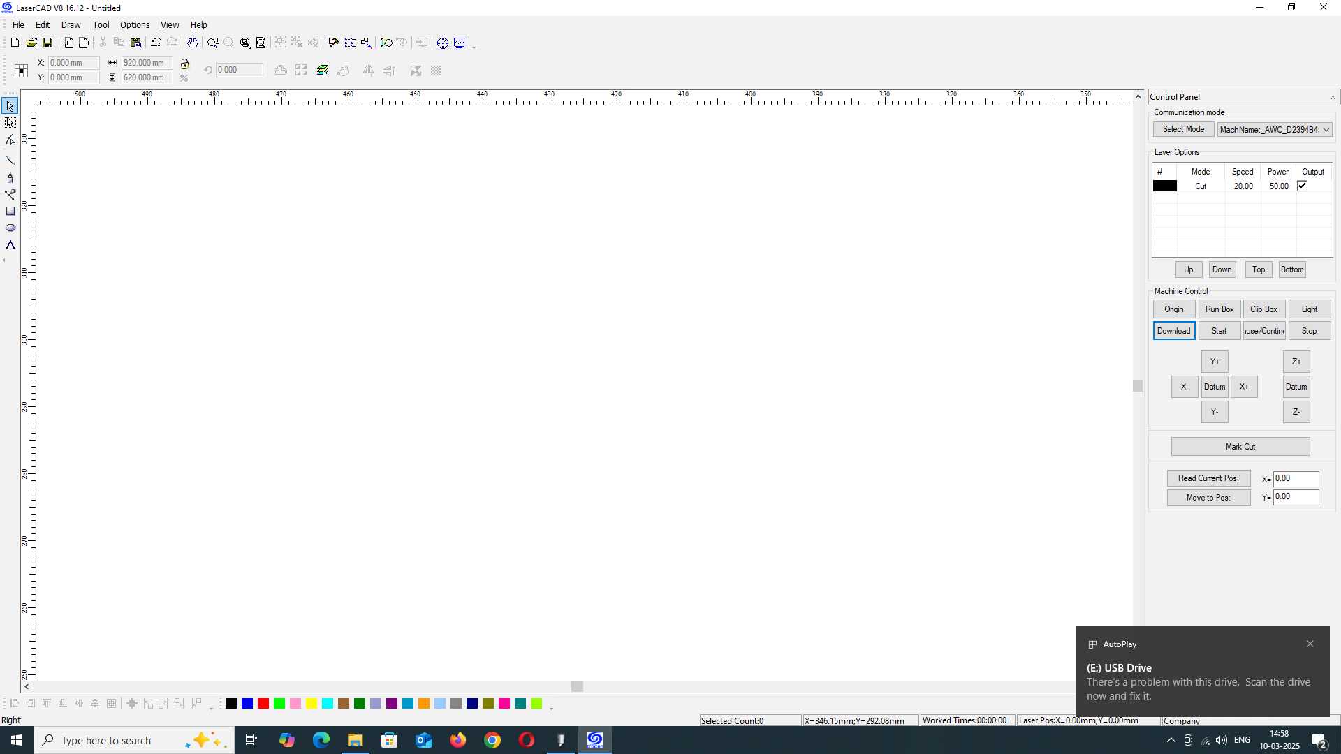
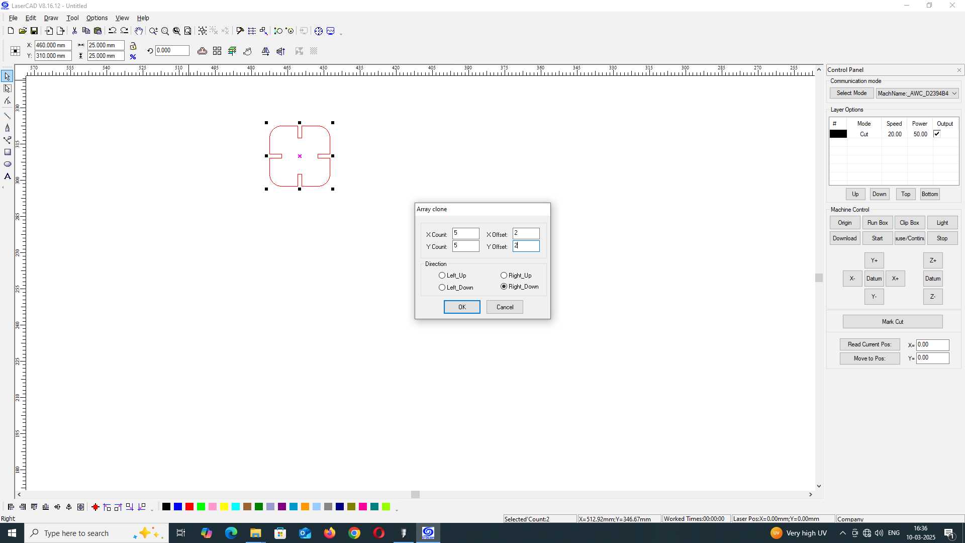
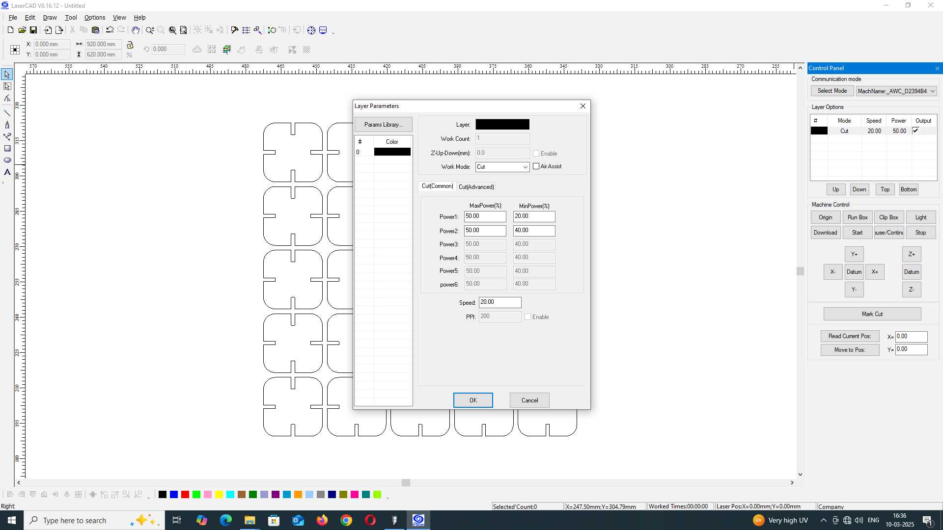
The first step is to open the laser CAD software and adjust the parameter settings for the cutting process. We set the
- speed to 20mm/s
- the power to 50%,
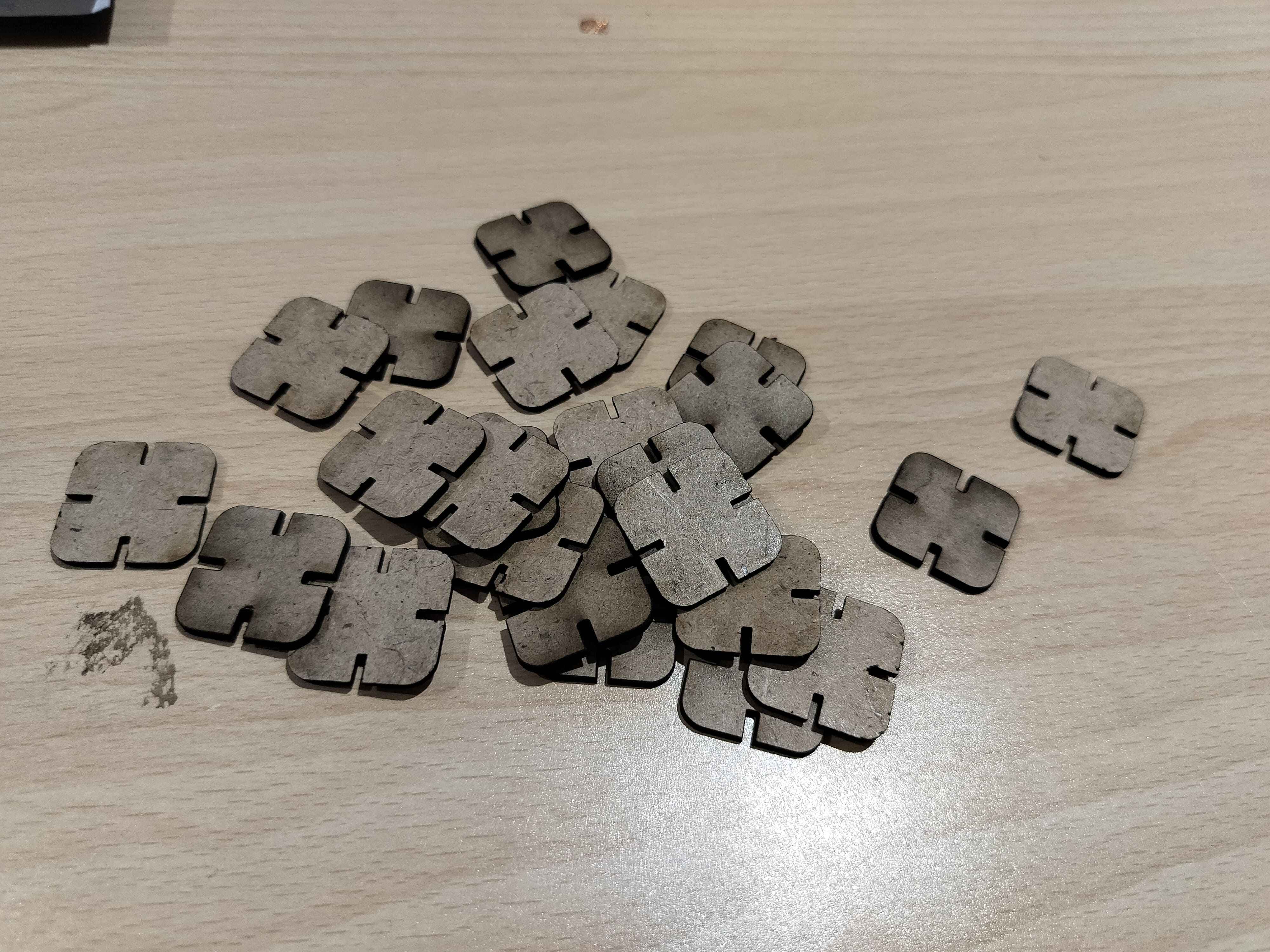
ensuring precise and clean cuts. Next, the DXF file is uploaded into the software. Using the array clone tool, I duplicated the design into 25 pieces, maintaining a 2mm distance between each piece. This arrangement optimizes material usage while ensuring enough space between cuts to prevent overlap or burning.
Running the Laser Cutter
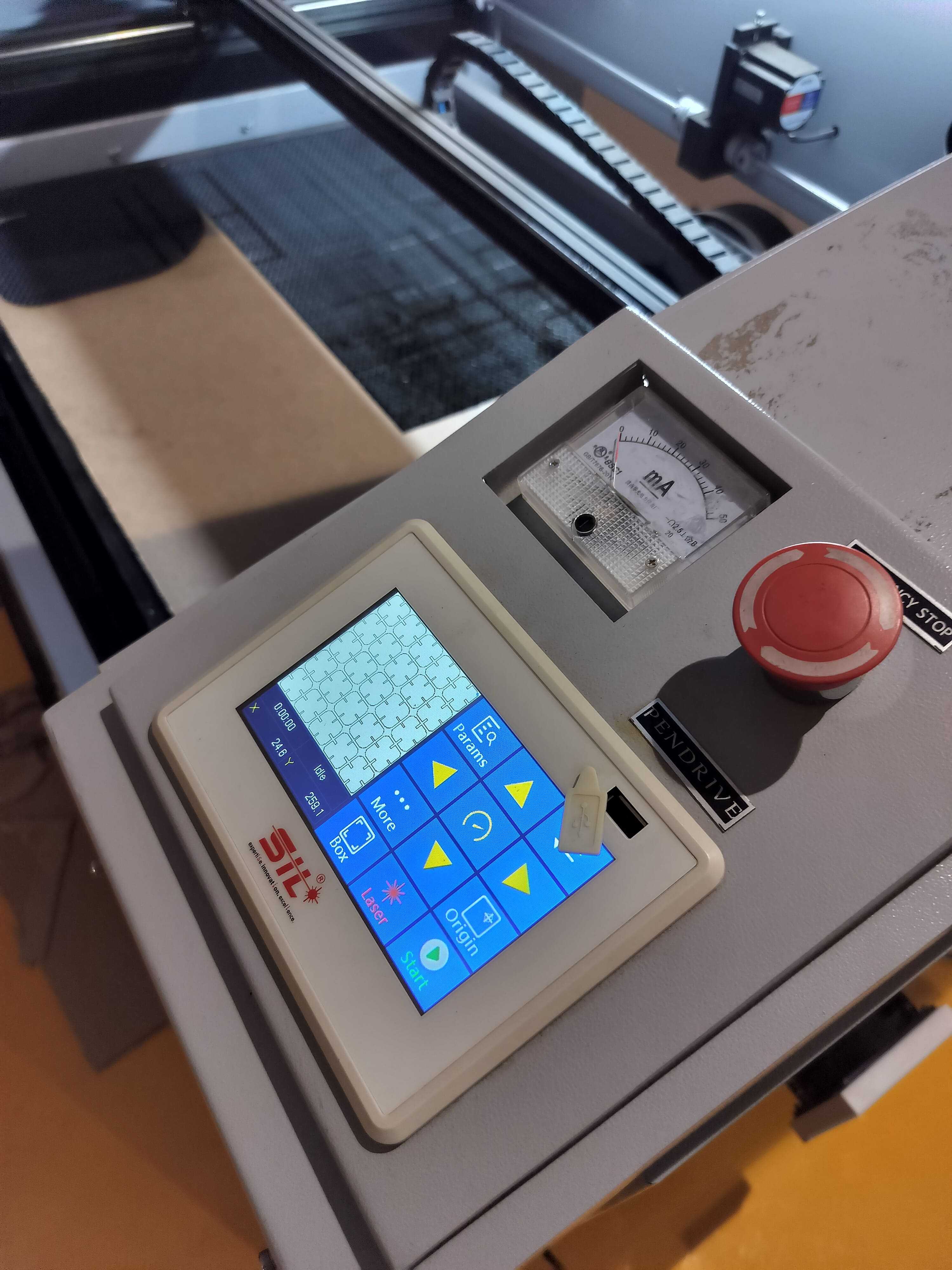
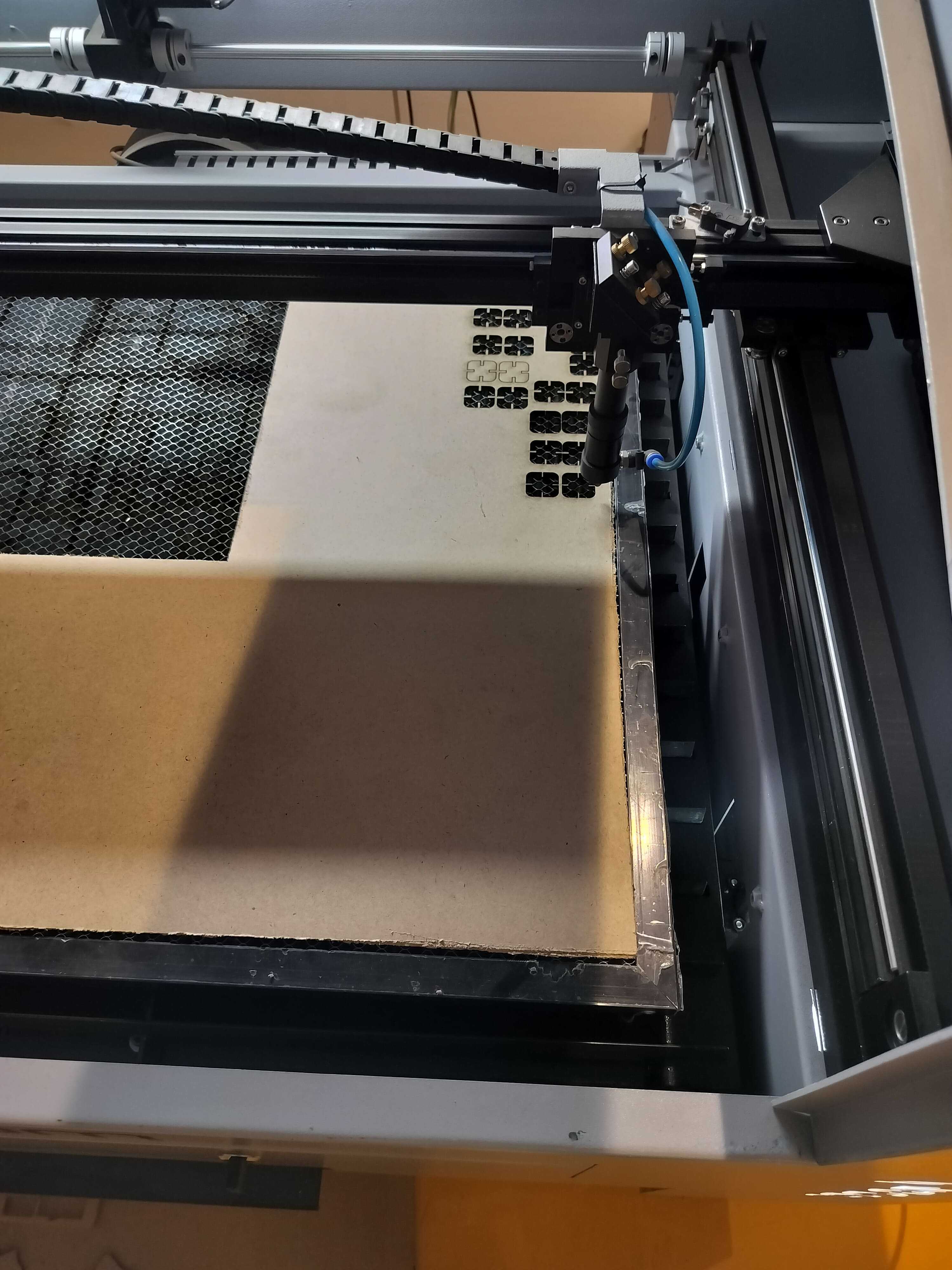
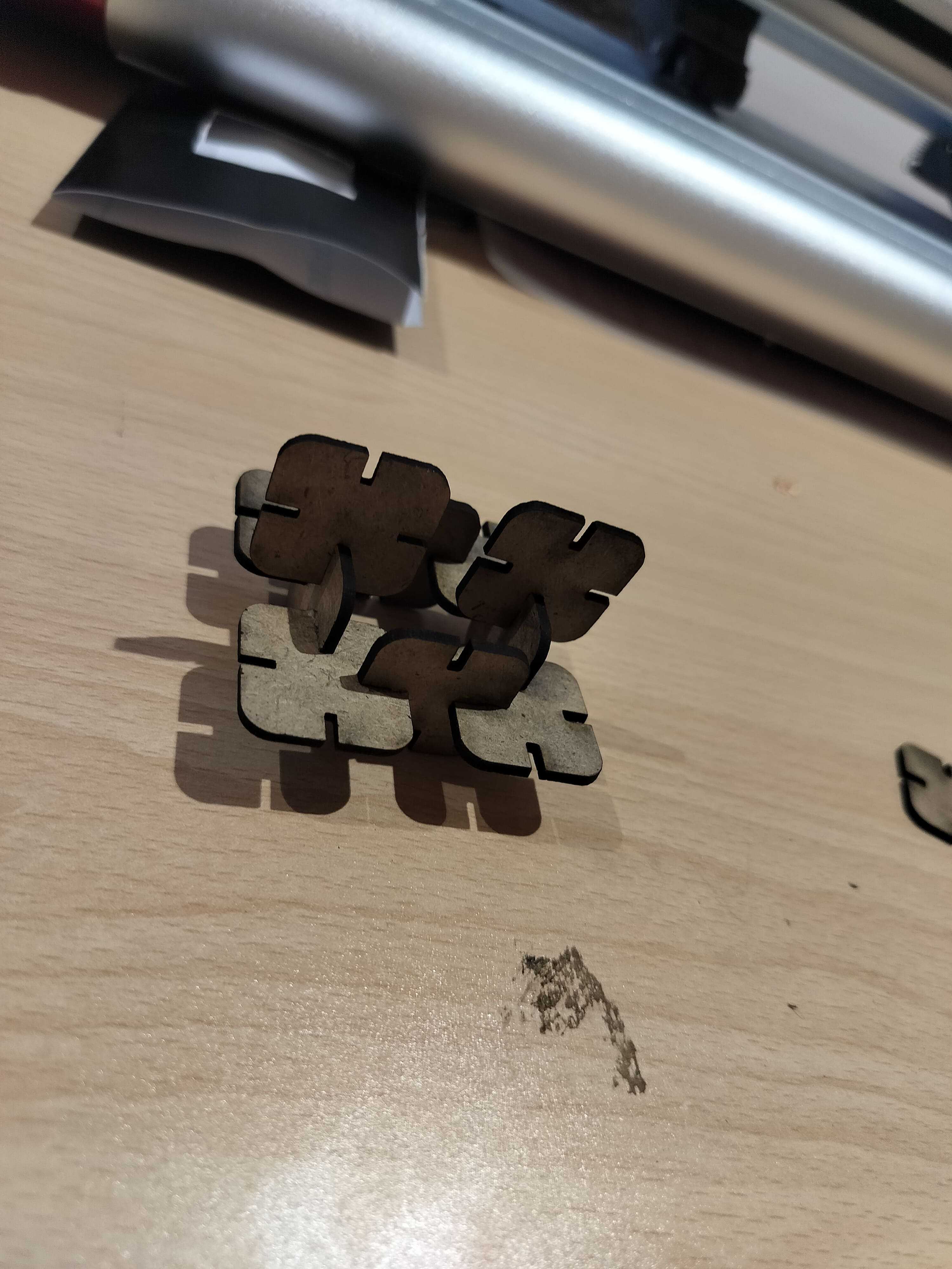
Once the design layout is ready, the file is uploaded to the laser cutting machine. Before starting the cutting process, I carefully position the laser pointer onto the wood, ensuring proper alignment. Using the control buttons on the display, I adjust the laser to the correct position, set it as the origin, and check if the required space is sufficient for all pieces. After confirming everything is set, I start the machine. Within 10 seconds, all pieces are precisely cut and ready for assembly, allowing me to use them for model creation.
Downloadable Files
3. Laser Hero Shot
4. Vinyl cutting
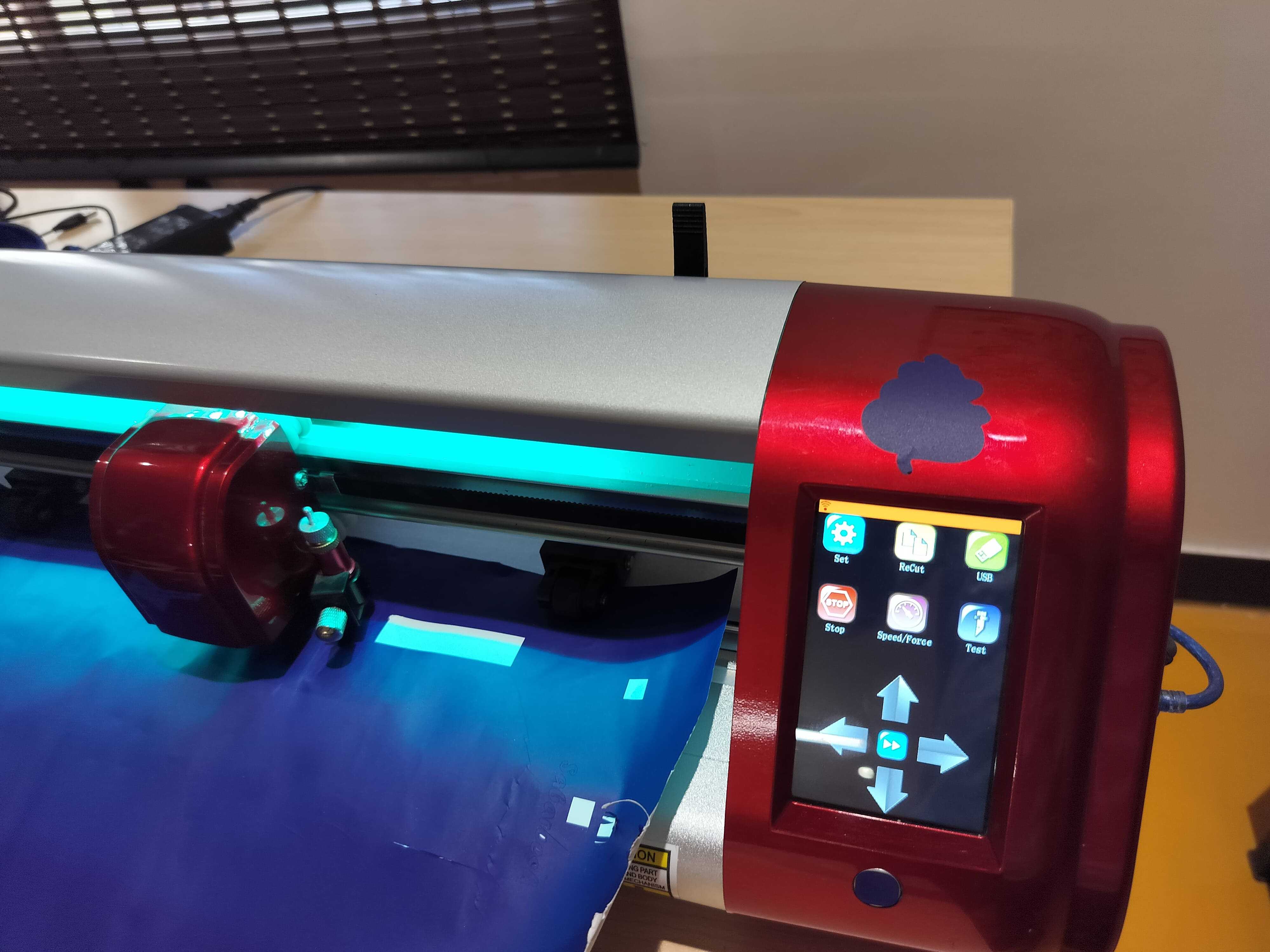
The SKYCUT C24 is a versatile 24-inch cutting plotter designed for both personal and professional applications. It offers a range of features that enhance precision and efficiency in cutting various materials.
Visit signmaster Official WebsiteKey Features:
- Cutting Force: Up to 800 grams, enabling the cutting of materials such as vinyl, cardstock, heat transfer vinyl (HTV), fabric, and EVA foam.
- Cutting Speed: Capable of reaching speeds up to 600 mm/s, facilitating swift project completion.
- Cutting Width: Supports a maximum media width of 720 mm, with an effective cutting width of 610 mm.
- User Interface: Equipped with a large touch screen for intuitive operation and precise control.
5. Vinyl Cutting Prepare
i. Preparing the Design for Cutting
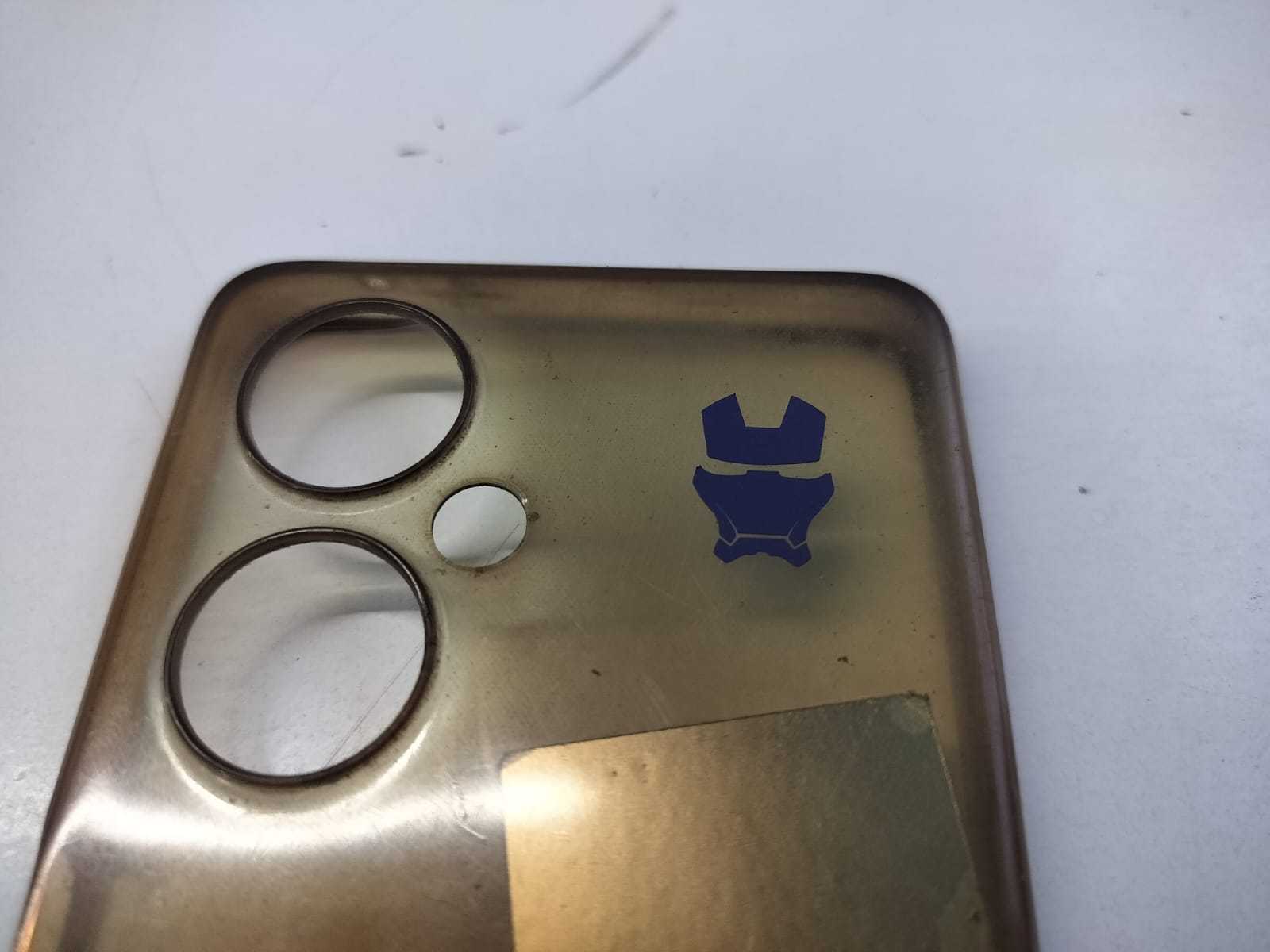
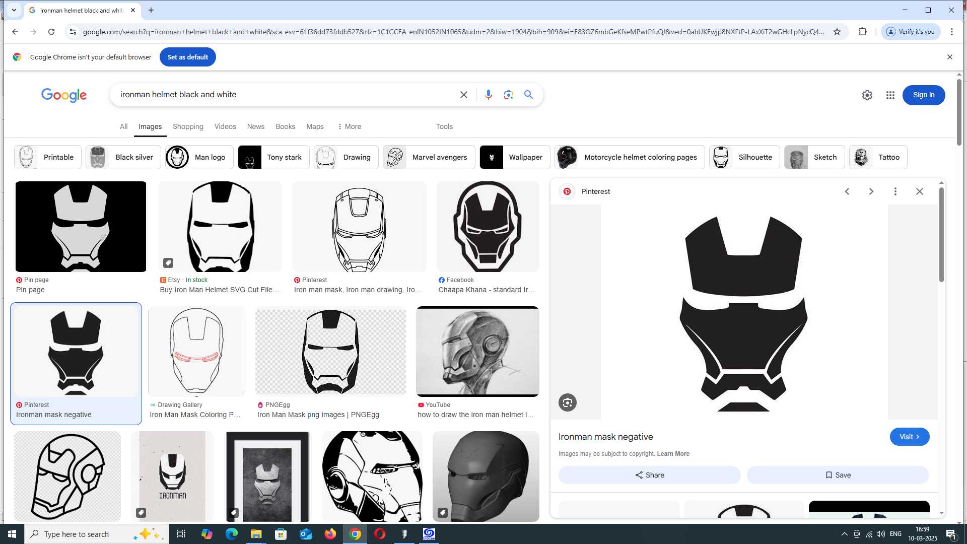
The first step in this process was to select an image that aligned with my fictional inspiration. Since I have always been fascinated by Iron Man, I decided to use an Iron Man mask design for my project. After finding a suitable image online, I downloaded it in JPG format and prepared it for cutting.
Next, I opened SignMaster Cut + ARMS 5.0, the software used for processing the design before sending it to the cutting machine.
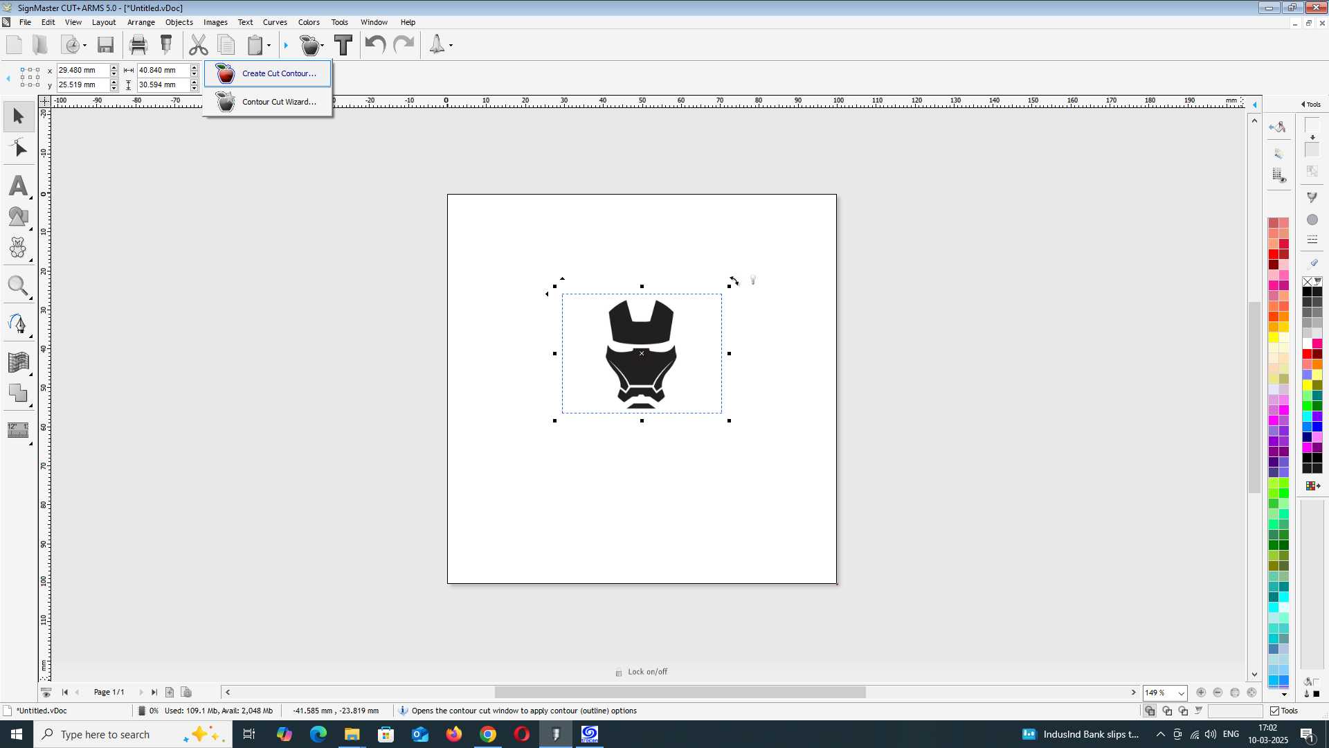
I imported the JPG file into the software and used the "Create Cut Contour" option. By applying the auto-trace function, the software automatically generated an outline of the Iron Man mask, making it ready for cutting. Once the tracing was complete, I positioned the design within the working area of the file, ensuring it was properly aligned and scaled.
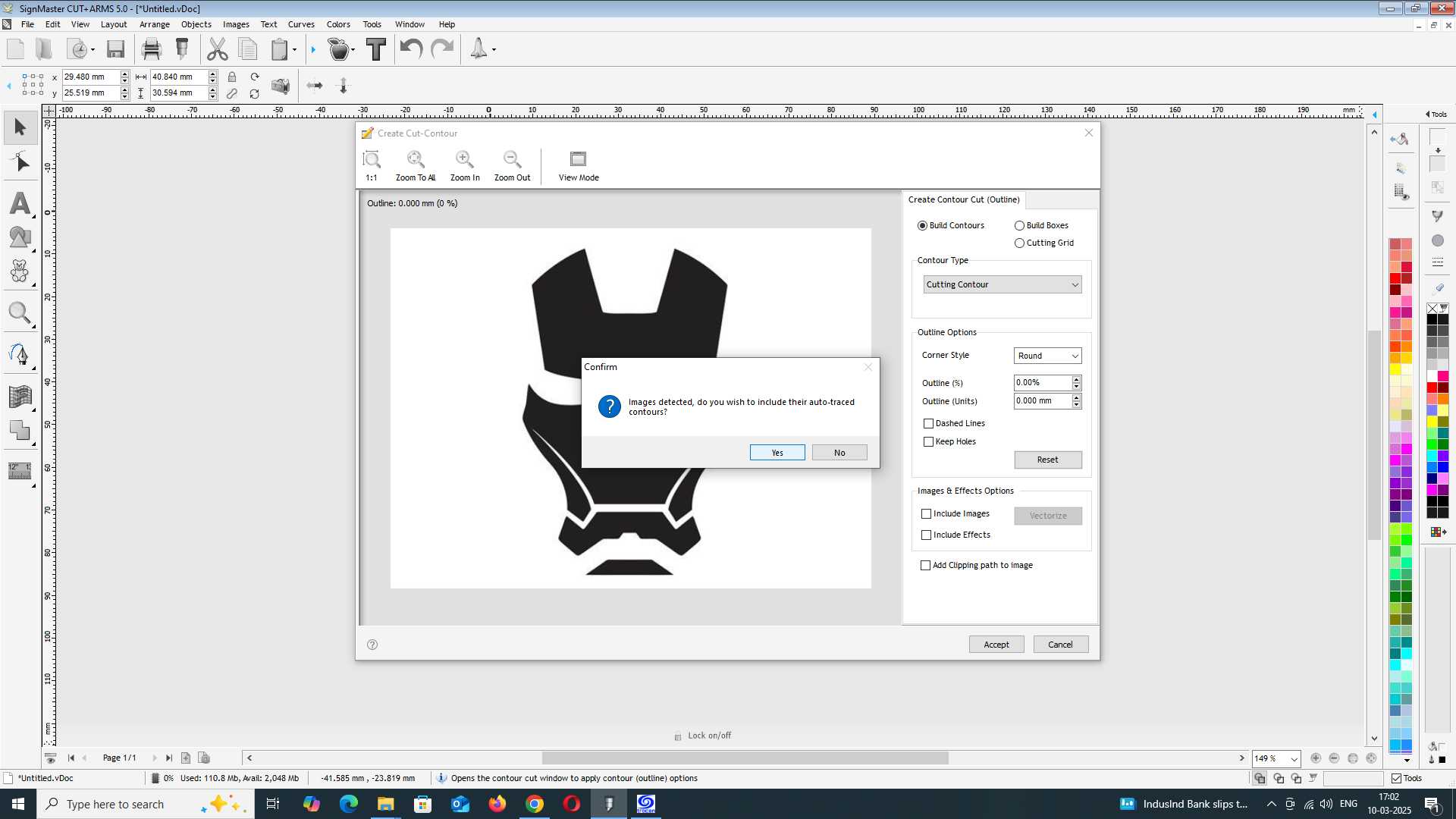
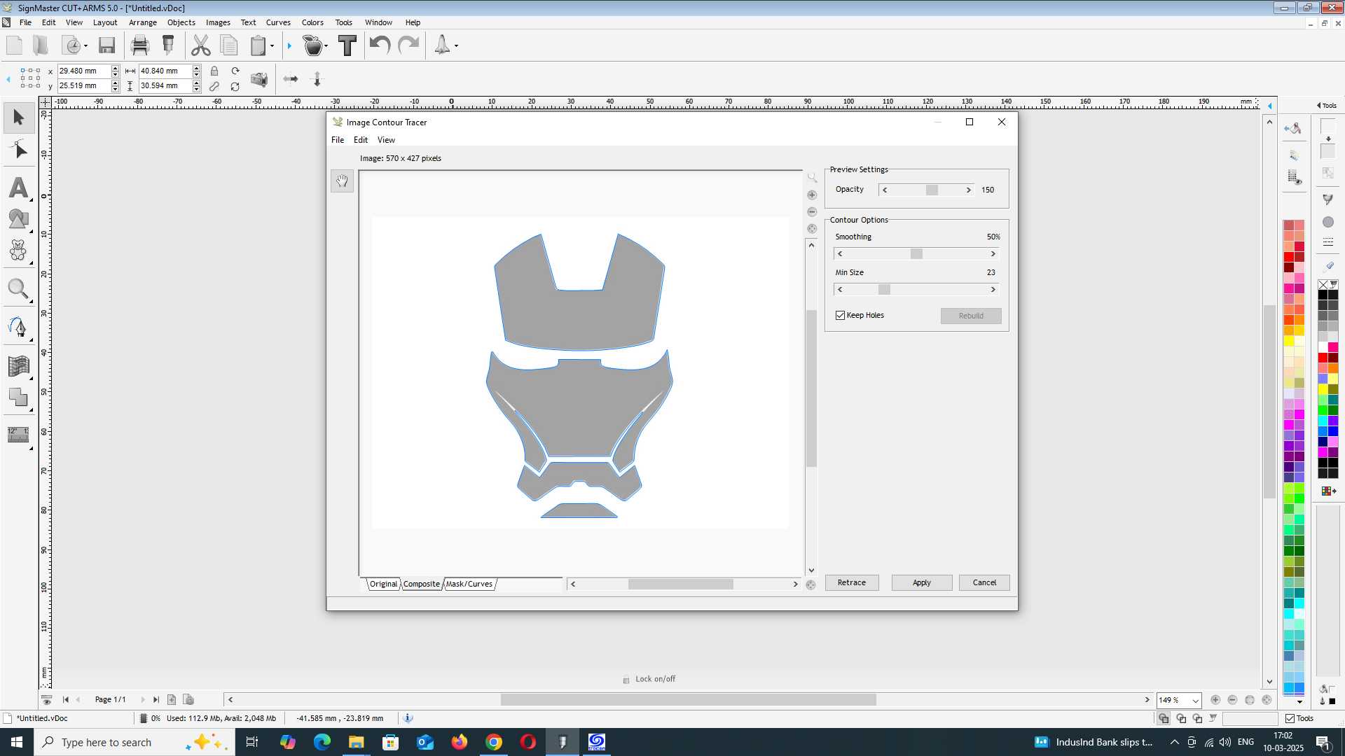
After finalizing the design, I moved on to the cutting process. Without making any modifications to the basic settings, I ensured that everything remained as recommended by the software. Before starting, I checked the vinyl spooler position to make sure it was correctly aligned.
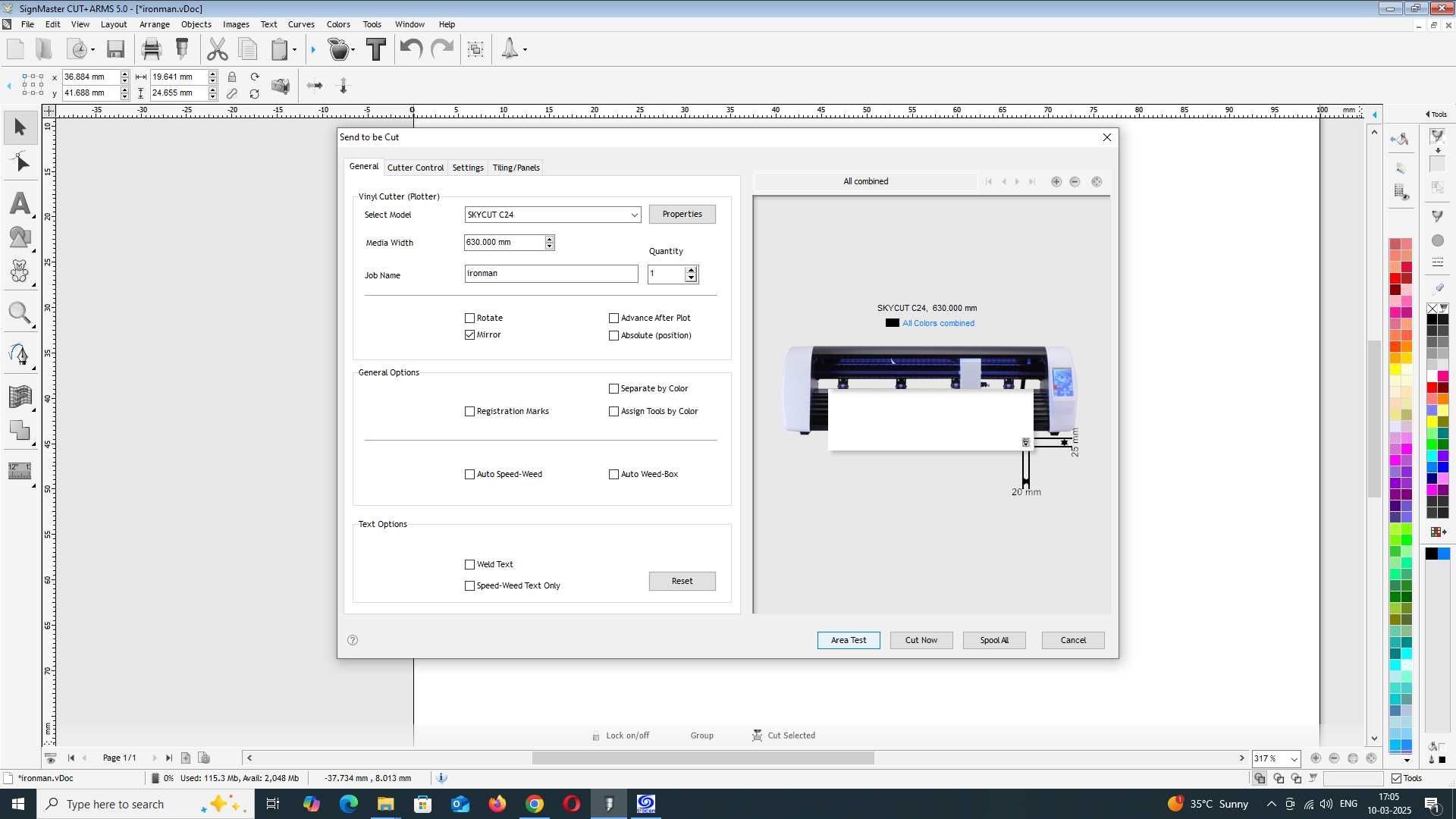
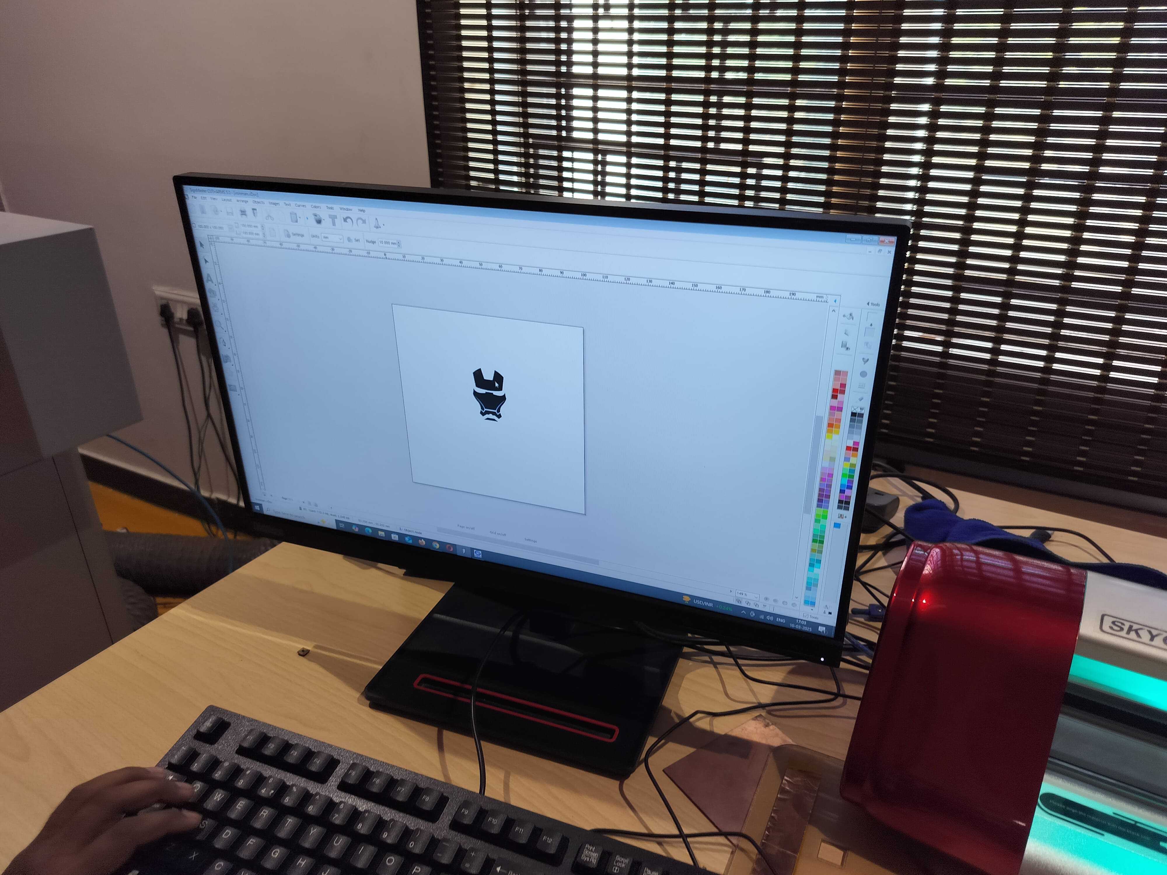
Using the controller interface on the cutting machine, I carefully adjusted the position of the spooler to ensure the vinyl sheet was properly placed. I then inserted the sheet material into the machine and made sure it was securely fitted. Once everything was set up, I started the machine, allowing it to precisely cut out the Iron Man mask design.
6. Vinyl Hero Shot
