Group Assignment – Week 3: Computer-Controlled Cutting
group assignment:
do your lab's safety training
characterize your lasercutter's focus, power, speed, rate,
kerf, joint clearance and types
General Lab Safety
Safety is the top priority in any lab environment. Before using any machine or handling materials, it is crucial to understand and follow safety protocols. Lab equipment often involves high power, sharp tools, chemical substances, and pressurized systems—all of which can pose serious risks if not used correctly.
To minimize hazards:
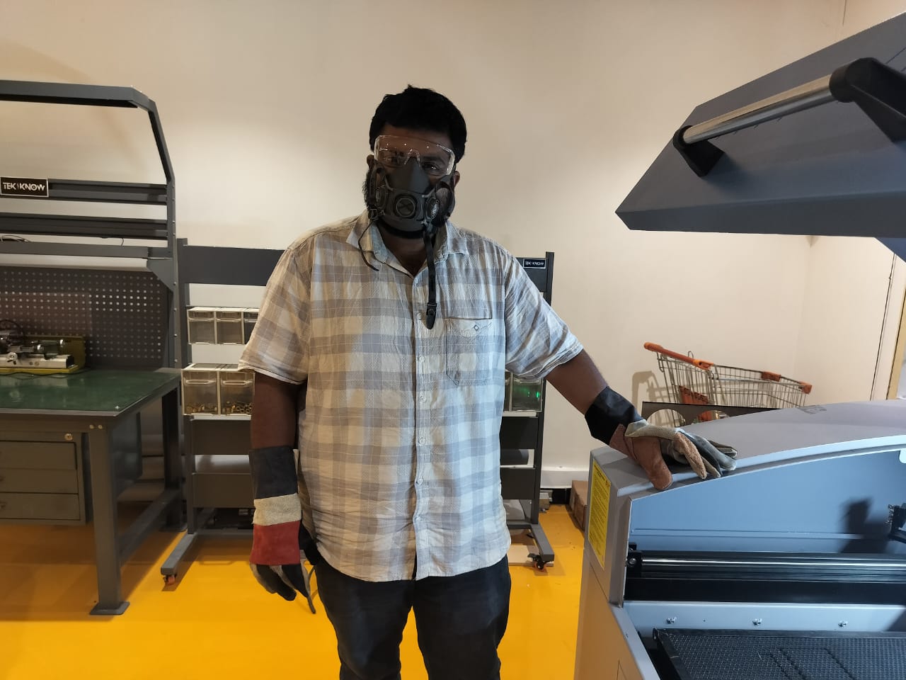
Always wear appropriate personal protective equipment (PPE) such as safety glasses, gloves, and closed-toe shoes.
All students are provided with personal gloves and masks.
Avoid loose clothing and jewelry, and tie back long hair to prevent entanglement in machines.
Maintain a clean and organized workspace—clutter increases the risk of accidents and reduces workflow efficiency.
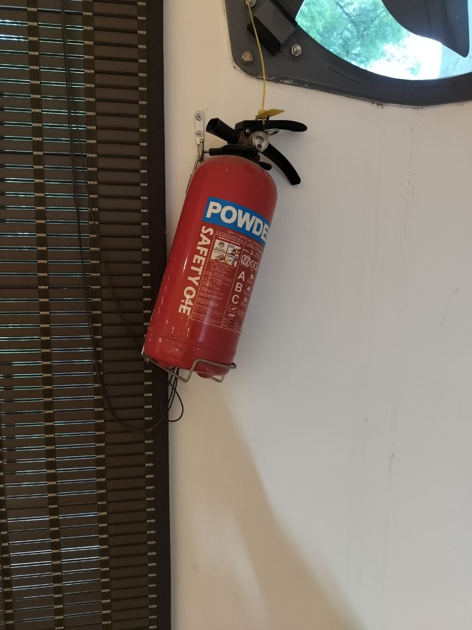
Before using any equipment, ensure it is in good working condition. Any malfunctions should be reported immediately. Emergency stops, fire extinguishers, first-aid kits, and eyewash stations must be easily accessible, and all users should be familiar with their locations. The lab orientation also included the location of the fire extinguisher, emergency exits, and floor plan.
CO₂ Laser Cutter Safety
The CO₂ laser cutter is a high-powered machine used to cut and engrave various materials. While powerful and precise, it poses hazards such as fire, eye injury, and exposure to toxic fumes.
Exhaust System
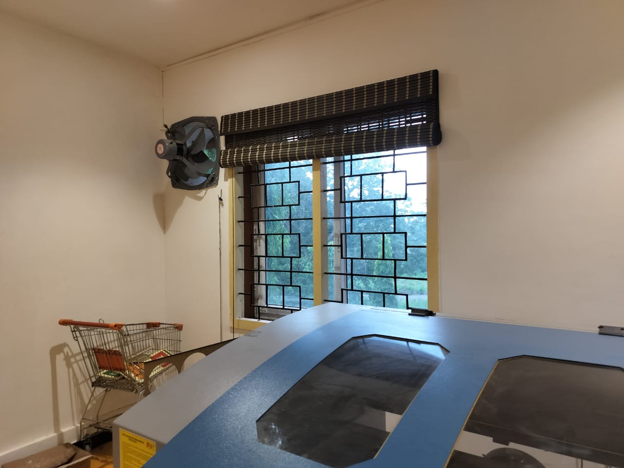
The machine is equipped with an exhaust filtration system that removes smoke and airborne particles created during the cutting process. A key component is activated charcoal, which absorbs harmful gases and VOCs (volatile organic compounds) released from materials like wood, acrylic, and plastic—helping maintain air quality and reduce fume exposure.
Material Safety
Not all materials are safe for laser cutting. Materials like PVC and ABS release highly hazardous fumes and should never be used. Always monitor the machine while in operation to prevent fire hazards, especially if the laser stays focused on one point too long.
After Use
Once cutting is complete, wait for the fumes to clear before opening the lid. Clean out any debris from the bed and turn off the machine properly. Use a CO₂ fire extinguisher if needed.
In Case of Fire
Do NOT open the lid immediately—more oxygen can worsen the fire.
Pause the machine to cut off the laser source.
If a small flame starts, cover it with a larger non-flammable sheet to block oxygen.
Use a CO₂ extinguisher if the fire spreads. Avoid water to prevent electrical damage.
Evacuate and call emergency services if the fire cannot be controlled.
Vinyl Cutter Safety
The vinyl cutter is a precision machine used for cutting thin sheets of vinyl and similar materials. Safety precautions include:
Ensuring the cutting blade is properly installed and set to the right depth.
Correctly aligning the vinyl sheet to avoid feeding errors.
Keeping hands away from the blade and rollers during operation.
Pausing the machine before removing jams.
Using weeding tools to remove excess material after cutting.
Cleaning the machine post-use to prevent material build-up.
Sandblasting Machine Safety
The sandblasting machine uses pressurized abrasive media to clean or texture surfaces, which creates dust and flying debris.
To operate safely:
Always wear goggles, gloves, and a dust mask.
Ensure the cabinet is fully sealed before use.
Never aim the nozzle at yourself or anyone else.
Use only approved abrasive media like glass beads or aluminum oxide.
Wait for dust to settle before opening the cabinet after use.
Clean the workspace and dispose of leftover abrasive properly.
Chemical Handling Safety
Working with chemicals requires extra precautions:
Always wear gloves, goggles, and a lab coat.
Work in a well-ventilated area or under a fume hood.
Store chemicals properly—flammables away from heat, and acids, bases, and solvents separately.
Check the Material Safety Data Sheet (MSDS) before use to understand each chemical’s risks.
In Case of Spills or Exposure
Use absorbent material for spills.
Wash skin or eyes with running water for at least 15 minutes.
Move inhalation victims to fresh air and seek medical help if needed.
Report large spills immediately.
Laser Cutting Overview
Laser cutting is a subtractive process where material is precisely removed using a focused laser beam. The beam heats and vaporizes the material along a pre-programmed path (via G-code), typically moving in the X and Y axes for 2D cuts.
Types of Laser Cutters
CO₂ Laser: Uses excited CO₂ gas to generate an infrared laser, guided with mirrors and lenses. Ideal for cutting wood, acrylic, and leather.
Fiber Laser: A solid-state laser that channels light through doped fiber optic cables. Excellent for cutting metals.
Key Parameters
a. Focus
- Adjusted Z-axis to find the optimal focus point.
- Best focus was identified by the thinnest kerf line.
- Result: Optimal focus distance = [insert value, e.g., 2 mm above material]
b. Power vs. Speed
- Created a test matrix with varying power and speed settings.
- Observed depth, charring, and cut-through effectiveness.
Power (%) | Speed (mm/s) | Result |
30 | 10 | No cut |
50 | 10 | Partial cut |
80 | 10 | Clean cut |
c. Kerf Measurement
- Cut a small square and measured the removed material width.
- Formula used:
Kerf = (Designed size – Measured size) / 2
- Result: Kerf = [e.g., 0.15 mm]
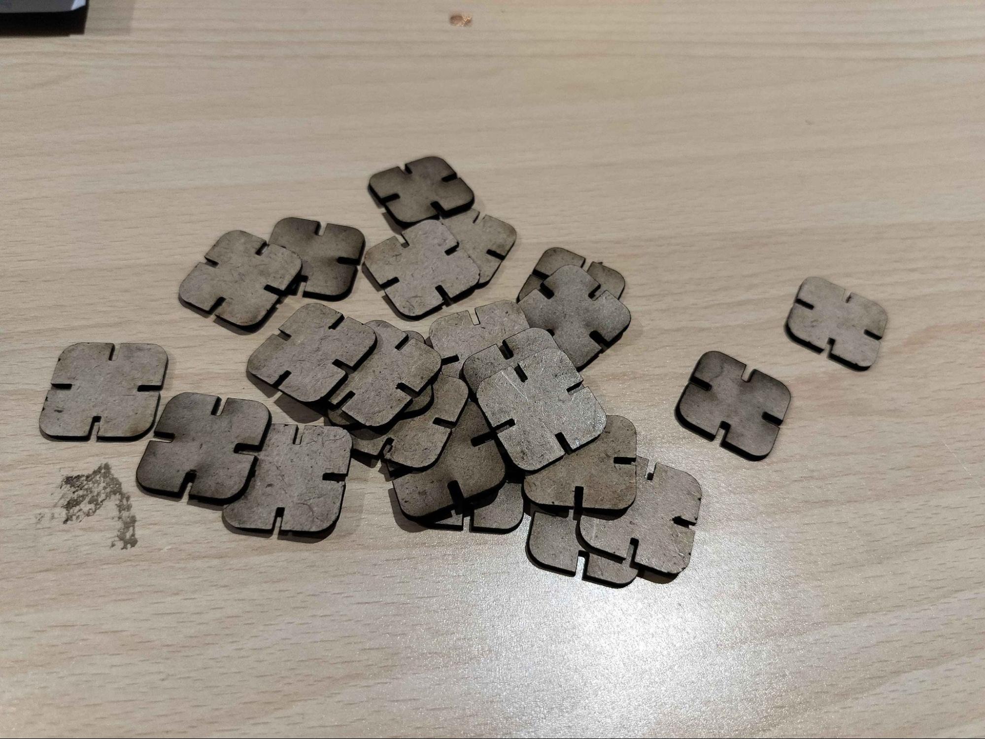
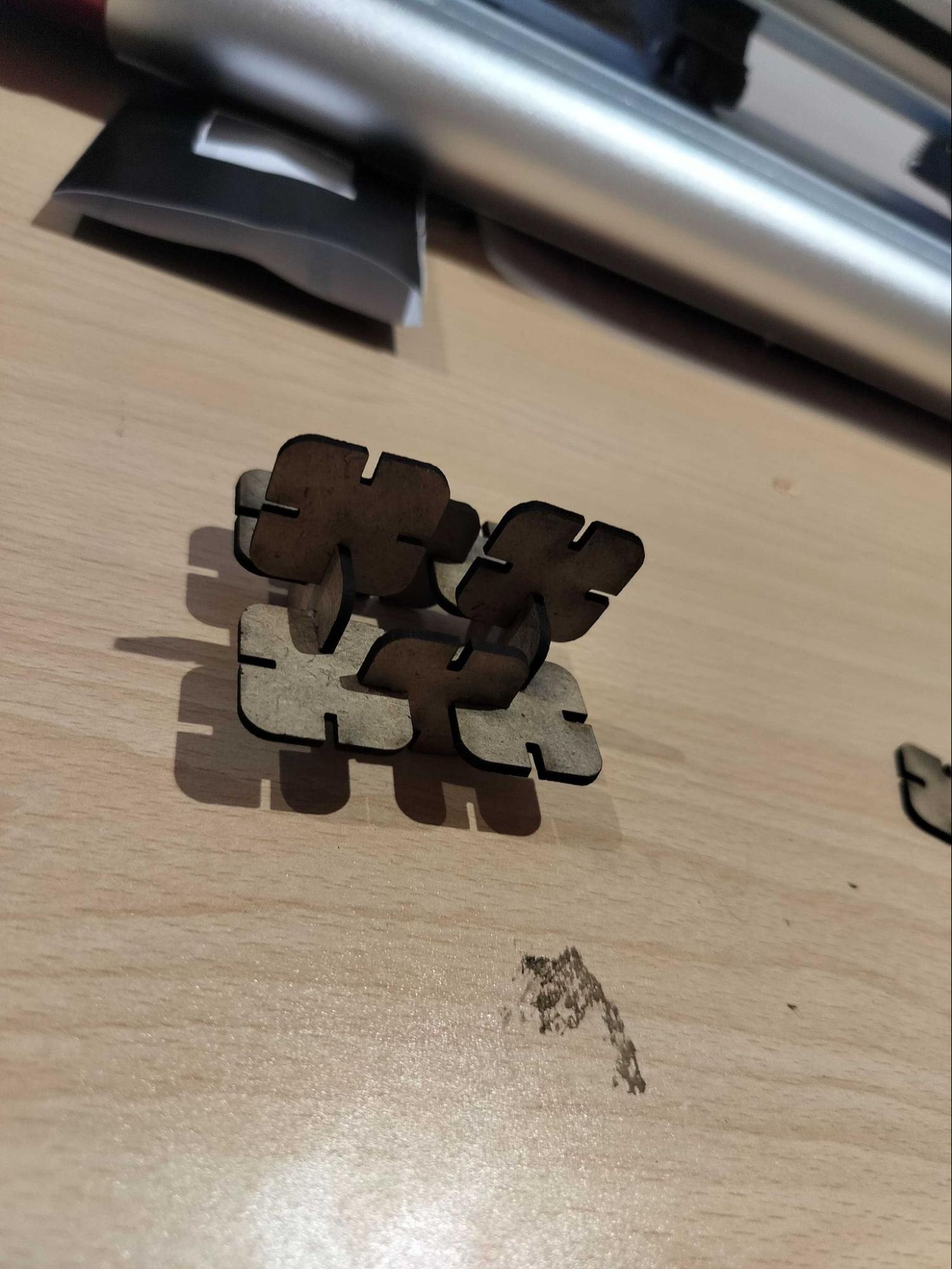
d. Joint Clearance
- Tested finger joints with different clearances: 0.1 mm to 0.4 mm.
- Evaluated fit (tight, loose, perfect).
Clearance | Fit |
0.1 mm | Too tight |
0.2 mm | Snug fit |
0.3 mm | Perfect fit |
0.4 mm | Loose fit |
Conclusion
Following safety protocols is essential for working in a lab environment. From personal protective equipment to machine-specific precautions, each measure helps prevent accidents and ensure efficient work. A clean, well-managed lab combined with awareness of emergency procedures promotes a safe and productive learning experience for everyone.
SILASERS Laser Cutting Machine E4040
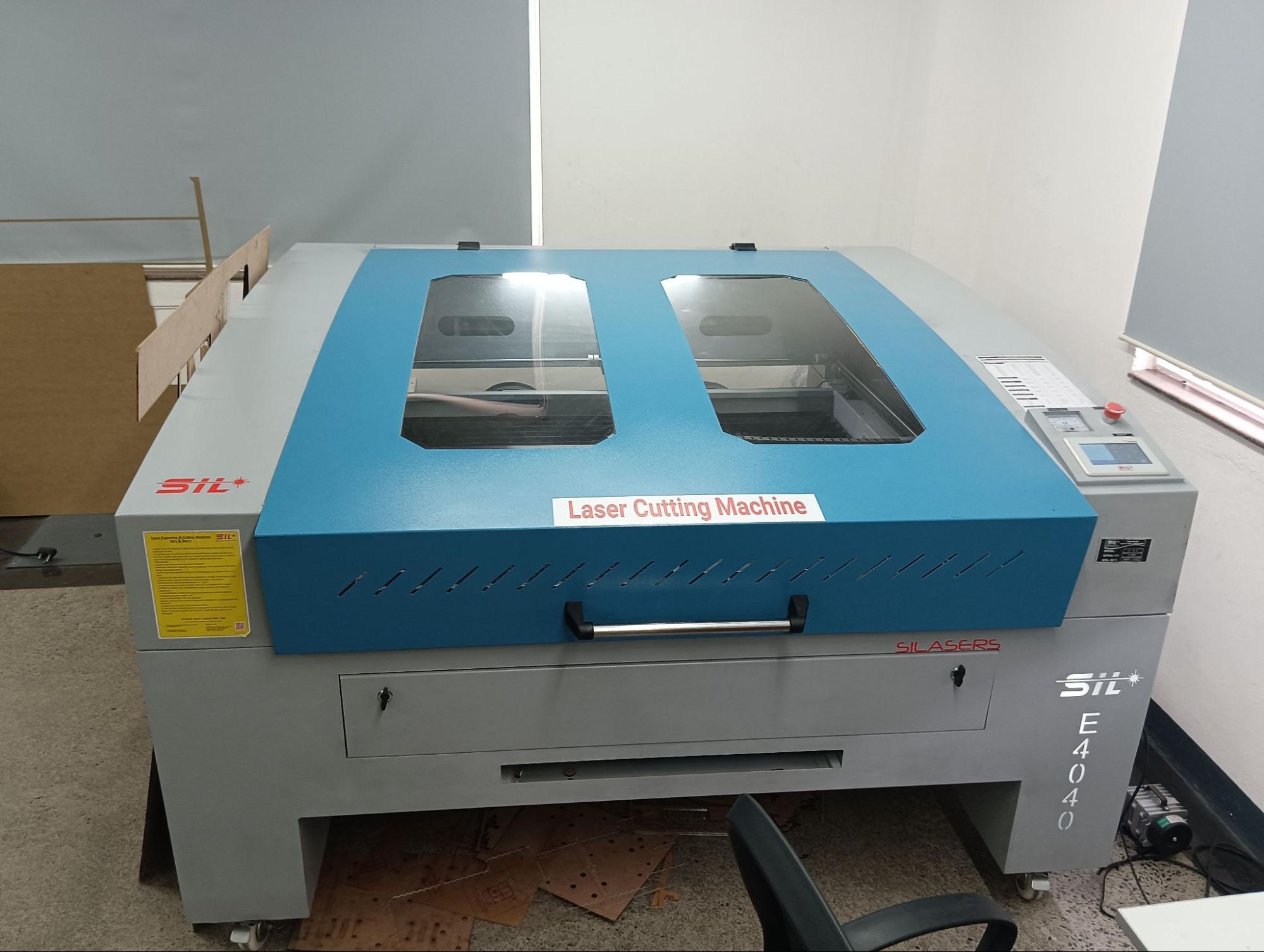
- Functionality: Used for cutting and engraving various non-metal materials such as acrylic, MDF, leather, fabric, paper, and plywood.
- Technology: Often utilizes a CO₂ laser source for clean cuts and detailed results, especially on materials like acrylic where it can produce flame-polished edges.
- Applications: Commonly used in industries for signage, crafts, prototyping, packaging, and decorative applications due to its ability to deliver sharp edges and fine detailing.
- Features: May include automatic operation and features like capacitive edge detection for precision.
- Certifications: SILASERS is ISO 9001:2008 Certified.
Technical Specifications
Laser Type | Co2 DC Glass Laser Tube / RF Metal Laser Tube |
Laser Power Option | Glass Tube – 60/80/100/130/150 Watt |
Wave Length | 10.6 μm |
Supply Voltage | AC 230 V ±0.05% / AC 415 V ±0.05% |
Reposition Accuracy | 0.1 mm (Max) |
Cutting Speed | 0 ~ 30000 mm/min |
Engraving Speed | 0 ~ 64000 mm/min |
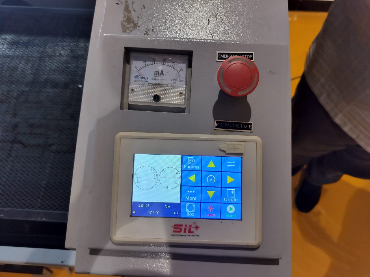
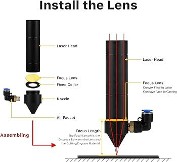
Controls
Although the machine is equipped with an autofocus feature, there are instances where manual focusing is required. This tool is specifically used to manually adjust the focus when needed.
Types Of Joints
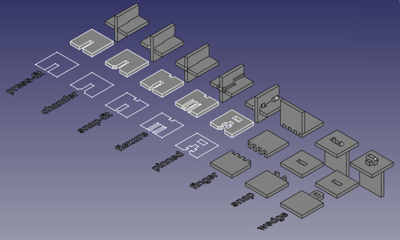
Laser cutting offers a variety of joint types that you can use for assembling parts.
The key to successful laser-cut joints lies in understanding proper clearance - the gap between mating parts that ensures they fit together correctly. This clearance typically ranges from 0.1mm to 0.3mm depending on material thickness and type. Getting the right clearance is crucial as too tight a fit can cause material cracking, while too loose a fit won’t provide adequate structural integrity.
Basic Joints
1. Finger Joints
- Interlocking “fingers” provide strong connections
- Ideal for wood and acrylic materials
- Require precise clearance for a snug fit
2. Edge Half Lap Joints
- Overlap material edges for robust connections
- Particularly effective in softer materials like wood
- Provide good structural integrity
3. Butt Joints
- Simplest joint type where two edges meet directly
- Requires reinforcement for strength
- Not recommended for load-bearing applications
Mechanical Joints Without Fasteners
4. Interlocking Joints
- Connect edges without adhesives or fasteners
- Ideal for flexible materials
- Can handle curved surfaces well
5. Loop Insert Joints
- Create disassemble connections
- Perfect for integrating fabric edges with rigid materials
- Offers a clean, stitch-less finish
6. Slot Hook Joints
- Involve slots and hooks that slide together
- Require careful design for proper alignment
- Beneficial for easy assembly/disassembly
Joints with Fasteners
7. Captive Nut Joints
- Use bolts and nuts held in place by the laser-cut material
- Prevent nuts from spinning during assembly
- Similar to cam lock fasteners in furniture
8. Screw Joints
- Quick and reliable
- Popular for many projects
- May lead to stripped holes with repeated use
9. Tapped Bolt Joints
- Involve threading the material to fit a bolt
- Provide durable connections
- May wear out with frequent use
10. Threaded Inserts
- More complex to install but long-lasting
- Ideal for frequent disassembly/reassembly
- Ensure secure fit every time
Compliant Joints and Mechanisms
11. Living Hinges
- Utilize material flexibility to create bendable connections
- Often used in packaging and folding designs
12. Snap-fit Joints
- Employ material elasticity for assembly
- Can be designed for specific angles or positions
Advanced Joints
13. Dovetail Joints
- Complex but adaptable for laser cutting
- Use etched lines as guides for manual adjustments
- Add distinctive appearance to wood and acrylic projects
14. Hammer Joints
- Use wedges to secure pieces without adhesives
- Effective for materials like wood
- Can be enhanced with glue for added strength
Parametric Design in Fusion 360
Parametric modeling in Fusion 360 is a powerful design approach where the model's dimensions and features are driven by defined parameters rather than fixed values. This allows for easy modifications and adaptability, making it ideal for tasks like engineering design, product development, and 3D printing.
Instead of manually changing each feature, users can assign variables and create formulas that automatically update the model when a parameter is changed. Fusion 360’s Modify → Change Parameters tool provides an efficient way to create, manage, and adjust these variables.
By combining constraints, feature-based modeling, and parametric rules, this method ensures design consistency, reduces repetitive work, and accelerates iteration cycles. As a result, parametric design not only improves workflow but also enhances precision and scalability across various design projects.
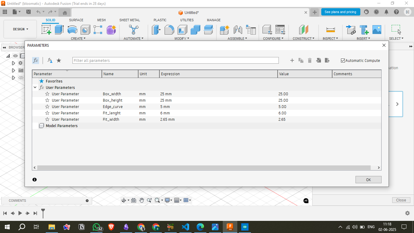
Parametric Design in Fusion 360
To begin the design, I used Fusion 360 and followed a parametric modeling approach. Instead of assigning fixed values to dimensions, I defined user parameters to make the model flexible and easy to modify. As shown in the first image, I created parameters like Box_width, Box_height, Edge_curve, Fit_length, and Fit_width, each with specific values. These parameters control the size and features of the design, and any change in these values automatically updates the entire model.
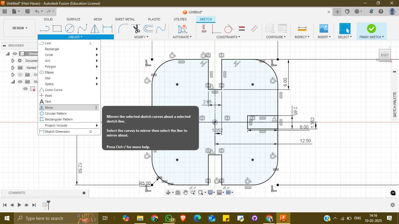
2D Sketch with Dimensions and Symmetry
Once the parameters were set, I moved on to sketching the design. In this step, I created a 2D profile of the component using lines, arcs, and constraints. To maintain symmetry and speed up the design process, I used the Mirror tool. This allowed me to draw only half of the profile and mirror it across a centerline to complete the other side. All dimensions in the sketch were linked to the parameters defined earlier.
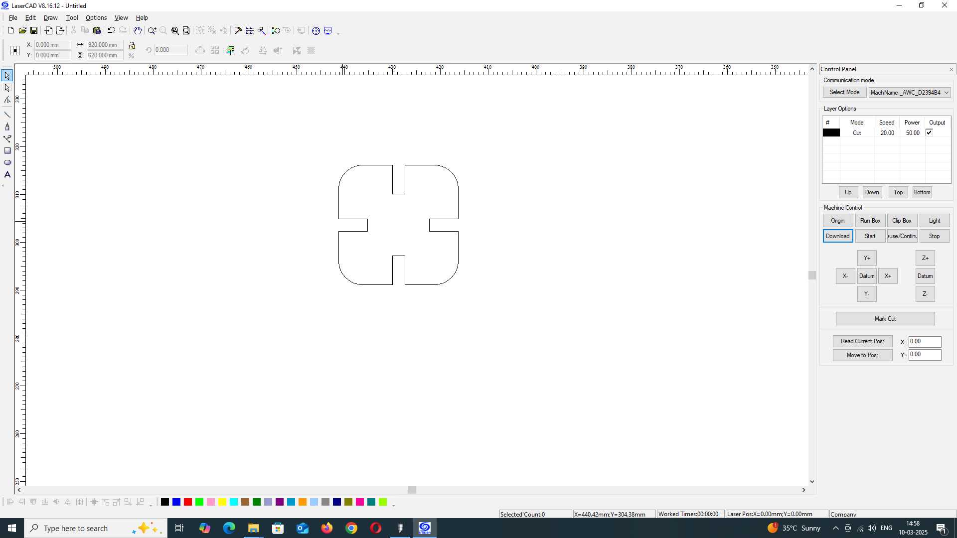
Laser Cutting Preparation in LaserCAD
After finishing the sketch and saving it as a DXF file, I imported the file into LaserCAD, which is the software used to prepare files for laser cutting. The first image in this section shows the initial import of the design with a single unit ready for processing.
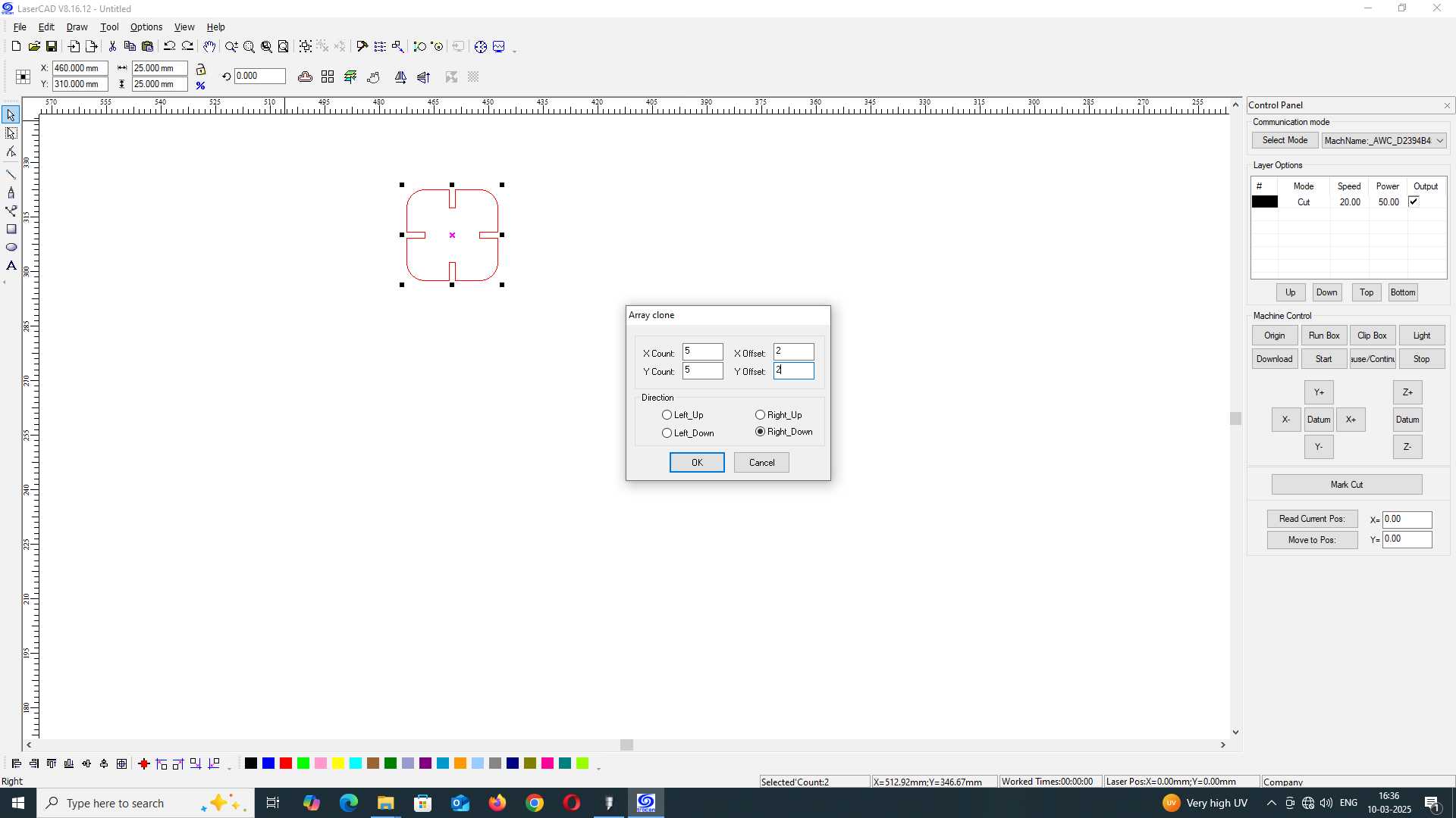
Creating a Cutting Array
To produce multiple units in a single cutting job, I used the Array Clone feature in LaserCAD. This allowed me to duplicate the design in a grid format by setting the number of rows and columns (X Count and Y Count) and defining the offset values between each part. This step is useful for batch production and optimal material usage.
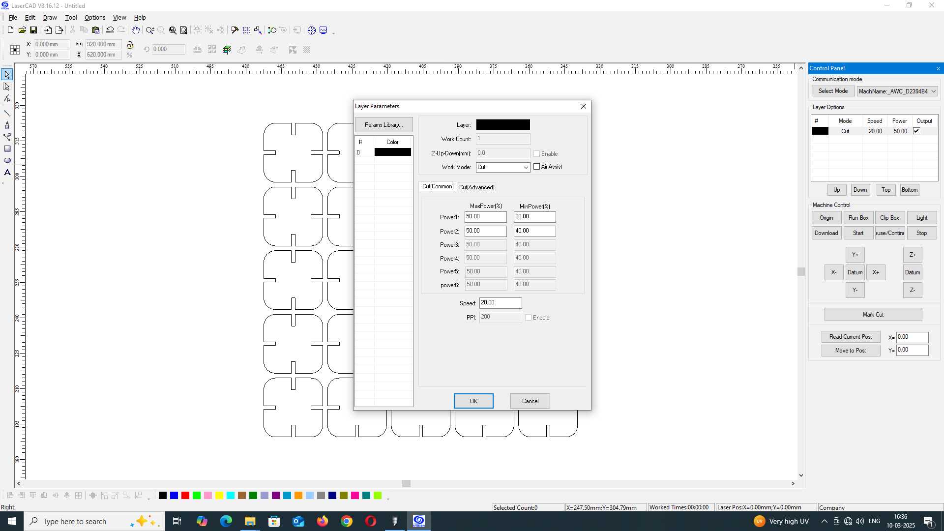
Laser Cutting Settings Configuration
Before sending the design to the laser cutter, I adjusted the cutting parameters such as power, speed, and the number of passes. These values are critical for achieving a clean and accurate cut depending on the material being used (like acrylic or plywood). I set the power levels, min/max values, and ensured that the work mode was set to "Cut". These settings ensure that the laser penetrates the material effectively without causing burns or incomplete cuts.
Final out
<<< Back to Lab Page