Prepared by Tshepho | Last Updated: June 15, 2025, 03:15 PM CAT
1. Introduction
1.1 Purpose
This document outlines the system integration design for the Inventory Tracking System, reflecting the implemented solution using a Raspberry Pi 3 GUI, RF Ideas RDR-7081AKU USB RFID reader, RP2040 microcontroller with RFID-RC522 for manual redundancy, 16x2 I2C LCD display, and CSV database. The system enables efficient inventory management, with the RP2040 processing manual RFID scans and updating the LCD, while the Raspberry Pi 3 handles CSV logging, GUI updates, and internal verification of scanned data.
1.2 Scope
The scope includes integrating the Tkinter GUI on Raspberry Pi 3, RDR-7081AKU for primary RFID scanning, RP2040 with RFID-RC522 for manual redundancy, a 16x2 I2C LCD for standalone data output, and CSV file system for tool tracking, borrower registration, and quantity management. Verification is handled internally on the Pi 3, with no external confirmation to RP2040. External network connectivity and hardware fabrication are excluded.
1.3 Definitions and Acronyms
USB HID: Human Interface Device (protocol for RDR-7081AKU).
I2C: Inter-Integrated Circuit (communication protocol for LCD).
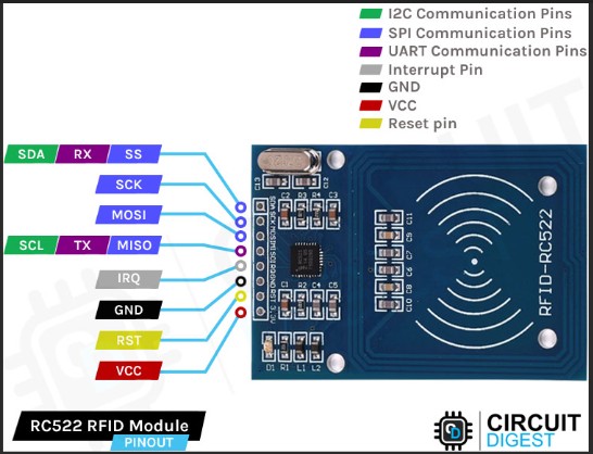
SPI: Serial Peripheral Interface (communication protocol for RFID-RC522).
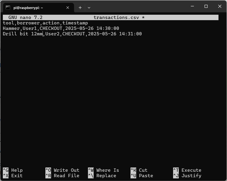
CSV: Comma-Separated Values (file format for transaction logging).
GUI: Graphica User Interface (interface hosting visible transactions)
UID: User Identities (the numbers programed on borrower IDs)
2. System Overview
2.1 System Description
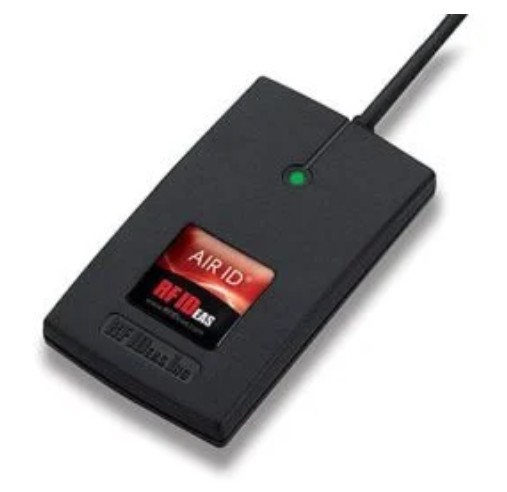
The Inventory Tracking System is a Raspberry Pi 3-based solution designed to track up to 20 tools in a storeroom. It primarily uses the RF Ideas RDR-7081AKU USB RFID reader to scan
tags via USB HID, with the RP2040 and RFID-RC522 as a manual redundancy mechanism. The RP2040 processes RFID scans when triggered and updates a 16x2 I2C LCD with scan results and Tkinter
GUI messages. The Raspberry Pi 3 manages the Tkinter GUI, logs transactions to a CSV file, and verifies scanned data internally. The system ensures reliability through dual-RFID capability
and dual-display output.
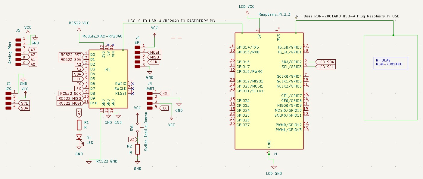
2.2 System Architecture
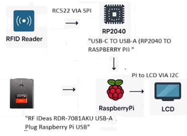
Front-End: Tkinter GUI on Raspberry Pi 3 for user input and display.
Primary RFID: RDR-7081AKU USB RFID reader using USB HID protocol.
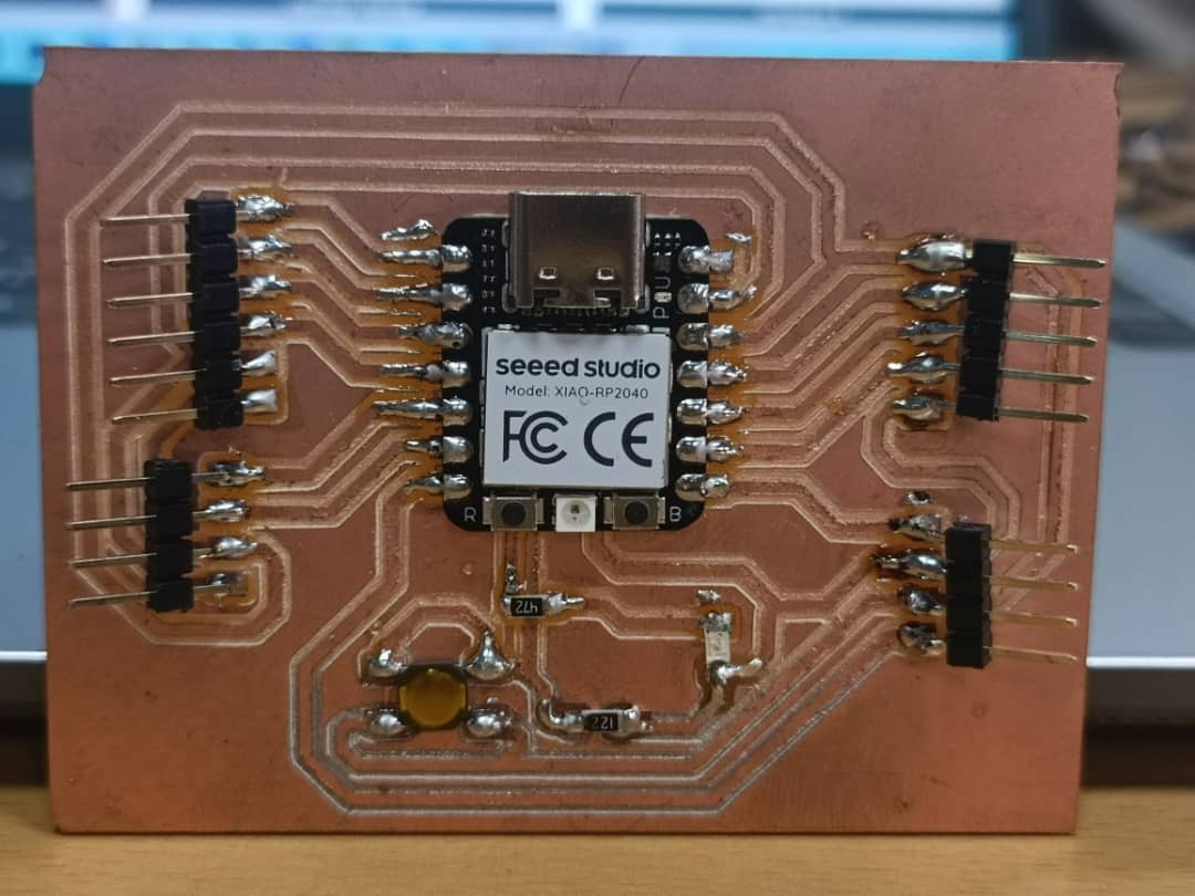
Redundancy: RP2040 microcontroller with RFID-RC522 for manual backup RFID scanning
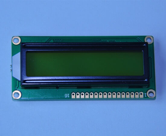
Display: 16x2 I2C LCD for standalone data output, controlled by the RaspberryPi, showing GUI messages and scan results.
Database: CSV file on Raspberry Pi 3 for transaction logging.
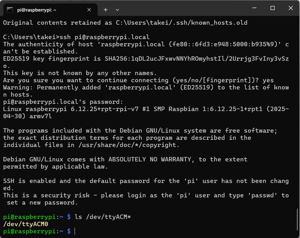
Interfaces: USB HID for RDR-7081AKU; serial communication (via /dev/ttyACM0) between Raspberry Pi 3 and RP2040 for RFID data and
LCD updates; I2C for LCD; SPI for RFID-RC522.
2.3 Integration Objectives
Enable seamless RFID scanning with RDR-7081AKU as the primary reader.
Implement RP2040 and RFID-RC522 as a manual redundancy mechanism.
Ensure the RP2040 processes scans and updates the LCD with scan results and Tkinter GUI messages when triggered.
Allow the Raspberry Pi 3 to handle CSV logging, GUI updates, and verify scanned data internally.
Maintain data consistency in the CSV log file.
Provide an intuitive user experience through dual interfaces (GUI and LCD).
3. Integration Requirements
3.1 Functional Requirements
Primary RFID scanning via RDR-7081AKU (USB HID keyboard emulation).
Manual redundant RFID scanning via RP2040 and RFID-RC522 (triggered by GUI button).
User authentication via RFID borrower tags (both readers).
Real-time GUI updates on Raspberry Pi 3 and LCD updates (via RP2040) reflecting scanned UIDs and GUI messages.
Internal verification on Raspberry Pi 3 of scanned UIDs and transactions.
3.2 Non-Functional Requirements
Performance: Response time under 2 seconds for RFID scans, GUI, LCD updates, and logging.
Scalability: Handle up to 20 items and 5 borrowers without performance degradation.
Security: Local CSV access restricted to Pi; serial communication unencrypted as implemented.
3.3 Constraints
Budget: Limited to ~$187.50 (including RDR-7081AKU and LCD, excluding reused components like RP2040, RFID-RC522).
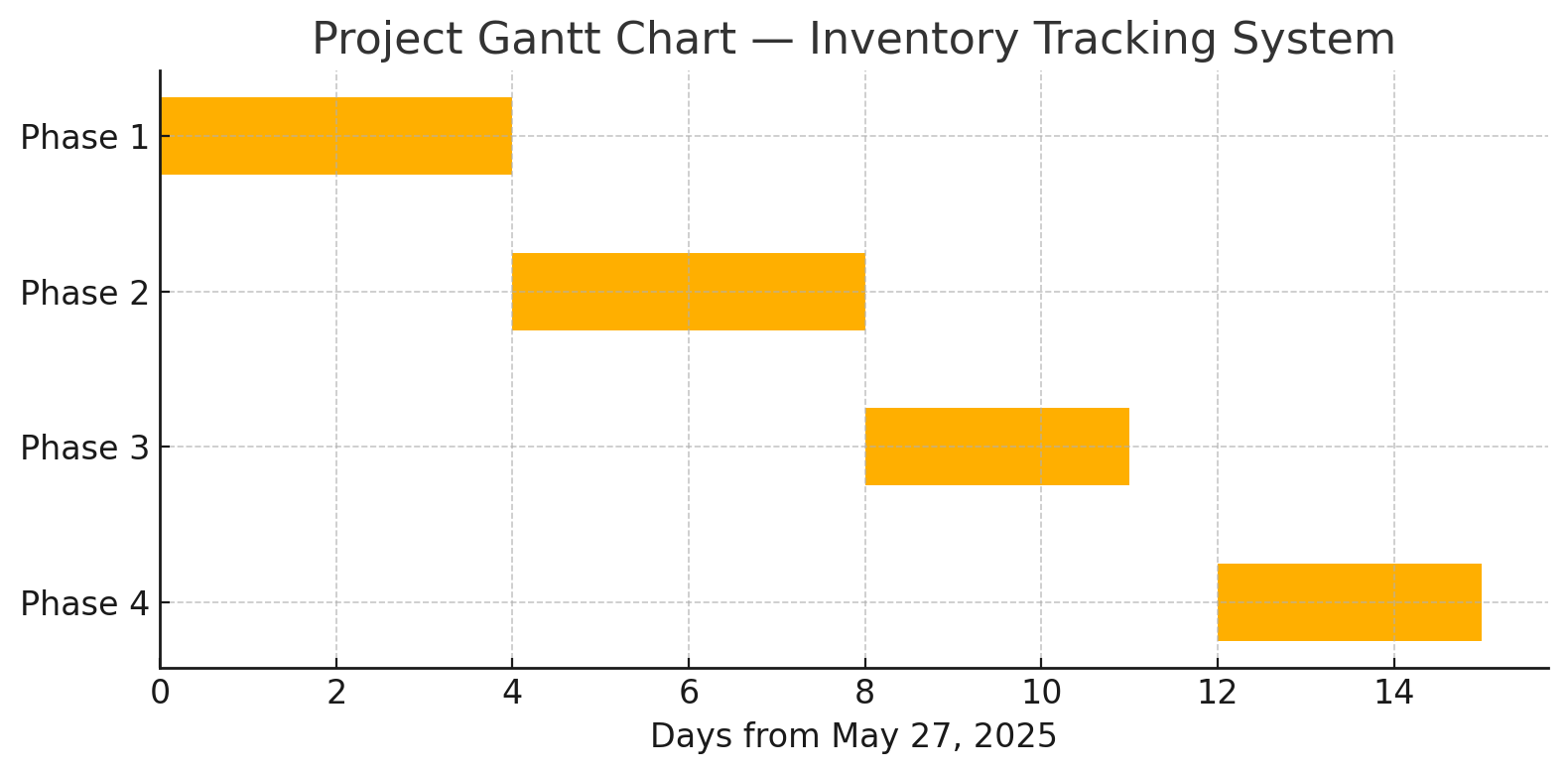
Time: 2-week timeline for full integration and testing (May 27 - June 9, 2025), with ongoing testing as of June 15, 2025.
Technology: Must use existing RP2040, Raspberry Pi 3, and Fab Lab tools.
4. Integration Design
4.1 System Components
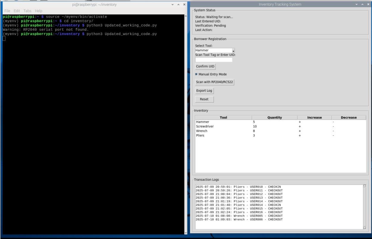
Component 1: Raspberry Pi 3 GUI: Handles user interface (Tkinter), CSV logging, USB HID input from RDR-7081AKU, sends TEXT: messages to RP2040, and verifies transactions internally.
Component 2: RDR-7081AKU RFID Reader: Primary RFID scanning via USB HID.
Component 3: RP2040 Microcontroller (Redundancy): Processes manual backup RFID scans with RFID-RC522, manages LCD display via I2C, and sends RFID: to Raspberry Pi 3.
Component 4: 16x2 I2C LCD: Displays RFID scan results and Tkinter GUI messages independently, controlled by the the Raspberry-Pi-3-B.
4.2 Integration Points
USB HID Interface: RDR-7081AKU sends RFID UIDs as keyboard input to the Raspberry Pi 3, captured via Tkinter Entry.
Serial Communication: Unidirectional communication from RP2040 to Raspberry Pi 3 at 9600 baud.
Command: RFID: (RP2040 sends UID after manual scan).
Command: TEXT: (Raspberry Pi 3 sends GUI messages or status updates to RP2040 for LCD display).
I2C Interface: RP2040 communicates with LCD (address 0x27) for display updates.
SPI Interface (Redundancy): RP2040 interfaces with RFID-RC522 for manual backup scanning.
4.3 Data Flow
Data flows from the RDR-7081AKU to the Raspberry Pi 3 as USB HID keyboard input, updating the Tkinter GUI and logging to CSV after internal verification. The Raspberry Pi 3 sends TEXT: commands to the RP2040 for LCD updates. For manual scans, the user triggers the RP2040 via the GUI button; the RP2040 reads the RFID-RC522, sends RFID: to the Pi 3, which processes it, updates the GUI, logs to CSV, and sends a TEXT: message for LCD display.
4.4 Interface Specifications
USB HID: RDR-7081AKU emulates a keyboard, sending UIDs as strings followed by a newline, captured via Tkinter Entry keystroke events.
Serial Endpoint: Raspberry Pi 3 to RP2040 at 9600 baud via /dev/ttyACM0.
Command: RFID: (RP2040 sends UID after manual scan).
Command: TEXT: (max 32 chars, Raspberry Pi 3 sends GUI messages to RP2040 for LCD display).
Response: OK (RP2040 acknowledges receipt and updates LCD, though not explicitly confirmed in code).
I2C: LCD address 0x27, 16x2 display, controlled by RPLCD.i2c.CharLCD with PCF8574 expander, limited to 16 characters per line.
SPI (Redundancy): RFID-RC522 pins on RP2040 (assumed RST/GP2, SS/GP3, MISO/GP4, MOSI/GP7, SCK/GP6) for manual backup scanning.
4.5 Integration Workflow
User scans an RFID tag with the RDR-7081AKU → UID is captured as USB HID input via Tkinter Entry widget.
Raspberry Pi 3 updates the Tkinter GUI, verifies the UID internally against the CSV file, and logs to CSV.
User manually triggers RP2040/RC522 scan via the “Scan with RP2040/RC522” GUI button → RP2040 reads UID with RFID-RC522, sends RFID: to Raspberry Pi 3.
Raspberry Pi 3 processes the RFID: message, verifies it internally, updates the GUI, and logs to CSV.
Raspberry Pi 3 sends TEXT: (e.g., “CHECKOUT ”) to RP2040 for LCD update after logging.
If RDR-7081AKU fails, user initiates failover by clicking “Scan with RP2040/RC522” → RP2040 reads UID, sends RFID:, and Pi 3 processes it.
User registers a borrower with a second scan via the “Register Borrower” button; verification and updates occur on both GUI and LCD based on Pi 3 logic.
5. Integration Strategy
5.1 Integration Approach
Primary integration via USB HID with RDR-7081AKU, with serial integration for RP2040/RFID-RC522 as a manual redundancy mechanism and for LCD updates, using a phased approach to test each component.
5.2 Tools and Technologies
Python 3.13.3: For Tkinter GUI and USB HID input handling on Raspberry Pi 3.
Arduino IDE: For RP2040 programming (assumed libraries for RFID-RC522 and I2C LCD).
OpenSCAD: For 3D enclosure design.
KiCAD: For custom PCB design.
Live Server (VS Code): For webpage documentation preview.
5.3 Phased Integration
6. Testing and Validation
6.1 Testing Strategy
Conduct unit tests for RDR-7081AKU (USB HID input), RP2040/RFID-RC522 (manual RFID scan, serial), and LCD (I2C output), integration tests for data flow and internal verification on Raspberry Pi 3, and end-to-end tests with 10 tools and 5 borrowers.
6.2 Test Cases
Test RDR-7081AKU scan returns UID within 2 seconds, triggers GUI update, and displays “Scanned: ” on LCD via TEXT: after internal verification.
Test RFID-RC522 scan (via RP2040 manual trigger) returns RFID: within 2 seconds, updates GUI and LCD after Pi 3 processes it.
Test Tkinter GUI message (e.g., “TEXT:Stock Check”) displays on LCD within 2 seconds via RP2040.
Test verification handshake: RP2040 sends RFID:, Pi 3 verifies internally (no CONFIRM:), logs to CSV within 2 seconds.
Test failover mechanism switches to RFID-RC522 manually via button, with consistent verification and logging.
6.3 Validation Criteria
99% success rate for RFID scans (both readers).
<1% error rate in USB HID, serial communication, I2C updates, and internal verification.
Data consistency in CSV logs and LCD display across both readers and GUI messages.
7. Deployment and Maintenance
7.1 Deployment Plan
Deploy on Raspberry Pi 3 with MicroSD card, with the LCD powered via the RP2040. Test in a staging environment (local workshop) before storeroom use, ongoing as of June 15, 2025.
7.2 Monitoring and Maintenance
Use Pi’s terminal logs and LCD output for debugging. Schedule weekly CSV backups to a USB drive and monitor serial RFID: and TEXT: messages.
7.3 Rollback Plan
Revert to a previous Python script, RP2040 sketch, and CSV backup if issues arise.
8. Risks and Mitigation
8.1 Potential Risks
RDR-7081AKU USB disconnection or failure.
RFID-RC522 range issues with multiple tags in manual redundancy mode.
Serial communication delays or failures during RFID: transmission.
I2C communication failures affecting LCD updates.
8.2 Mitigation Strategies
Implement manual failover to RFID-RC522 with user prompt if RDR-7081AKU fails.
Test RFID-RC522 range with shielding (e.g., acrylic separators).
Implement timeout mechanisms for serial communication (e.g., 2 seconds) and retry logic.
Ensure stable I2C connections and verify serial port availability.
9. Conclusion
The Inventory Tracking System is implemented with a working integration of the Raspberry Pi 3 GUI, RDR-7081AKU, RP2040 with RFID-RC522 for manual redundancy, 16x2 I2C LCD, and CSV logging as of June 15, 2025, 03:15 PM CAT. The system provides efficient inventory tracking with internal verification on the Pi 3, dual-display updates, and manual failover. Ongoing testing and enclosure packaging are in progress to meet storeroom management needs.
10. Appendices
10.1 References
Raspberry-Pi-3-B Data sheet
RP2040 Datasheet (Raspberry Pi Foundation).
RFID-RC522 Datasheet (NXP Semiconductors).
RF Ideas RDR-7081AKU Manual (RF Ideas).
Andrew’s FabAcademy Project (May 15, 2025).
10.2 Glossary
Middleware: Software facilitating communication (not used here but noted for future).