Embedded Networking and Communications
Group Work Page Documentation
Documented the breadboard setup, wiring, code, and results on the group page.
Link to Group Work Page
Individual Assignment: Design, Build, and Connect Node(s)
Objective: Set up two XIAO-RP2040 development boards on a breadboard to communicate via a wired network (UART) and send a signal from Node 1 (sender) to Node 2 (receiver) to control an LED and an SG90 servo motor.
Introduction
This project focuses on embedded networking and communications, involving both group and individual assignments. The group assignment demonstrates wired communication between two Seeed Studio XIAO-RP2040 development boards on a breadboard, using UART to send a signal from Node 1 (sender) to Node 2 (receiver) to control an LED and an SG90 servo motor. The individual assignment involves designing and building the receiver node using the Seeed Studio XIAO-RP2040 microcontroller, with an SG90 servo motor and an LED as outputs, controlled via the wired network (UART), and programmed using the Arduino IDE. The node was designed in KiCAD and assembled on a custom PCB.
EDA Tool Used: KiCAD
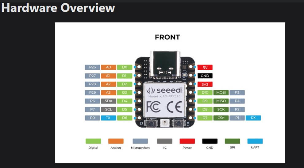
Microcontroller Chosen (Individual Assignment): Seeed Studio XIAO-RP2040
Node Design and Build
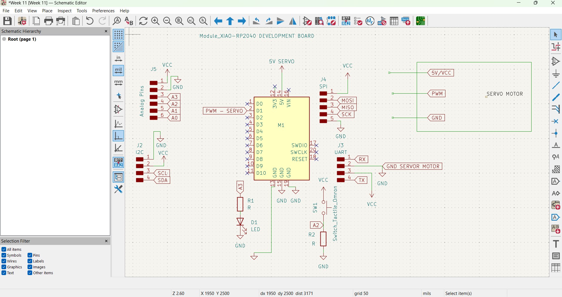
- Designed the receiver node using the XIAO-RP2040 with an SG90 servo motor and an LED as outputs. The schematic and PCB layout were created in KiCAD.
- Schematic of the Node:
- SG90 Servo Motor: To control a mechanical output.
Message Transmission Demonstration
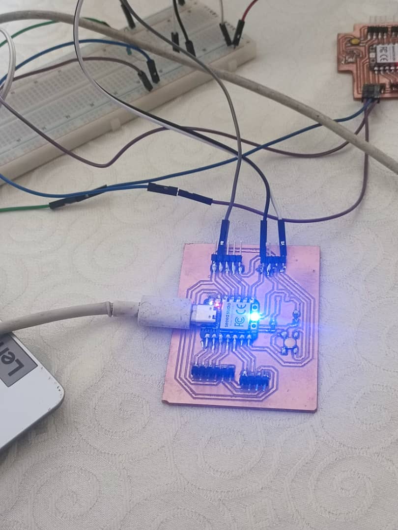
- Setup: Assembled two XIAO-RP2040 boards on a breadboard, connected via UART (wired communication). Node 1 acts as the sender, and Node 2 as the receiver.
- Wiring: Node 1 TX (D6) to Node 2 RX (D7), Node 1 RX (D7) to Node 2 TX (D6), common GND between both boards.
- Node 2 has an LED on D10 with a 220Ω resistor to GND, and an SG90 servo motor on D9 (signal), with VCC to the soldered 5V pin on Node 2’s XIAO-RP2040.
- Code Snippet (Sender - Node 1):
void setup() { Serial1.begin(9600); // UART communication on D6 (TX) and D7 (RX) Serial.begin(115200); // For debugging on Serial Monitor } void loop() { // Send command to turn on LED Serial1.println("LED_ON"); Serial.println("Sent: LED_ON"); delay(2000); // Send command to move servo to 90 degrees Serial1.println("SERVO_90"); Serial.println("Sent: SERVO_90"); delay(2000); // Send command to turn off LED Serial1.println("LED_OFF"); Serial.println("Sent: LED_OFF"); delay(2000); // Send command to move servo to 0 degrees Serial1.println("SERVO_0"); Serial.println("Sent: SERVO_0"); delay(2000); } - Code Snippet (Receiver - Node 2):
#include
Servo myservo; const int ledPin = 10; // D10 (GPIO 10) for LED String message = ""; void setup() { Serial1.begin(9600); // UART communication on D6 (TX) and D7 (RX) Serial.begin(115200); // For debugging on Serial Monitor myservo.attach(9); // D9 (GPIO 9) for servo pinMode(ledPin, OUTPUT); digitalWrite(ledPin, LOW); myservo.write(0); // Start at 0 degrees } void loop() { while (Serial1.available()) { char incomingChar = Serial1.read(); if (incomingChar == '\n') { if (message == "LED_ON") { digitalWrite(ledPin, HIGH); Serial.println("LED turned ON"); } else if (message == "LED_OFF") { digitalWrite(ledPin, LOW); Serial.println("LED turned OFF"); } else if (message == "SERVO_90") { myservo.write(90); Serial.println("Servo moved to 90 degrees"); } else if (message == "SERVO_0") { myservo.write(0); Serial.println("Servo moved to 0 degrees"); } message = ""; } else { message += incomingChar; } } } - Result: The Serial Monitor on Node 2 displayed messages confirming the received commands (e.g., "LED turned ON", "Servo moved to 90 degrees"). The LED on Node 2 turned on and off as commanded, and the servo moved between 0 and 90 degrees.
Individual Reflection
Learned about wired communication using UART between XIAO-RP2040 boards. Collaboration was effective, but we faced issues with cross-talk between the UART lines, which were resolved by ensuring a solid common ground and reducing the baud rate to 9600.
Result
The XIAO-RP2040 receiver node successfully received commands via the wired network (UART) from the sender node. The LED turned on and off as commanded (e.g., "LED_ON" turned it on, "LED_OFF" turned it off). The SG90 servo motor moved to the specified angles (e.g., "SERVO_90" moved it to 90 degrees, "SERVO_0" moved it to 0 degrees). The Serial Monitor on the receiver node displayed messages confirming the actions (e.g., "LED turned ON", "Servo moved to 90 degrees").
Challenges
- Initially attempted to use a water flow sensor and LCD, but both failed (reported on April 10, 2025). Switched to using an SG90 servo motor and an LED for the individual assignment. Powered the servo at 3.3V initially, which resulted in reduced torque; soldered a pin to the XIAO-RP2040’s 5V pin, improving performance. Faced issues with UART communication due to noise on the breadboard; resolved by ensuring a solid common ground and using a lower baud rate (9600).