Computer-Controlled Machining
- Complete your lab's safety training
- Test runout, alignment, fixturing, speeds, feeds, materials and toolpaths for your machine
- Document your work to the group work page and reflect on your individual page what you learned
- Make (design+mill+assemble) something big
#.Group assignment:
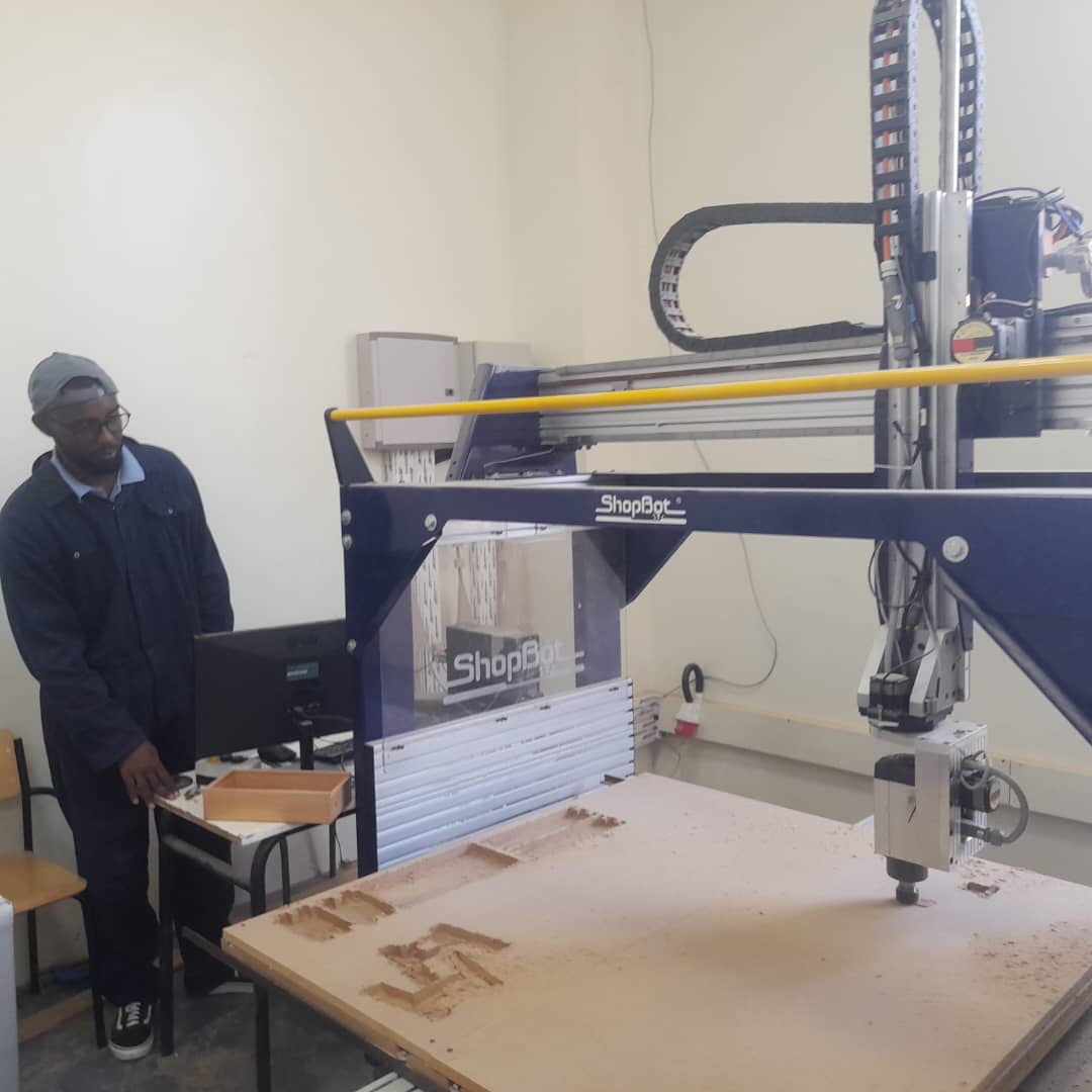
As a group, we began by completing the lab's safety training to ensure we followed all necessary precautions while working with the machines. We then tested spindle runout and alignment to confirm the machine’s accuracy. After properly fixturing the material, we experimented with different speeds and feeds to determine the most effective settings. Finally, we tested our toolpaths to ensure smooth operation and reliable results during the actual machining process.
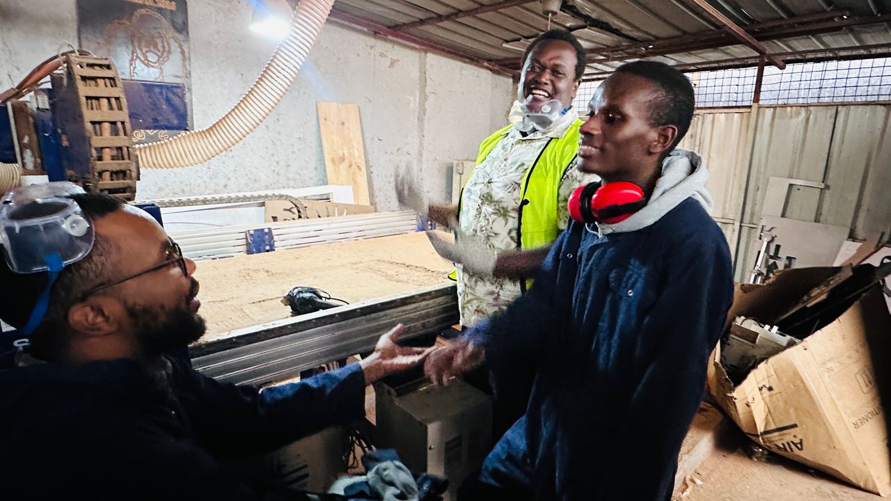
😄 Here's a fun mental image of us around the CNC.
Group assignment link
#.Individual assignment
For this assignment, the goal was clear: design, mill, and assemble something big using computer-controlled machining. I wanted to create something that was not just large in scale but also practical and relevant to my daily life. That's how I came up with the idea of an adjustable computer stand, a piece I could use both for my Fab Academy tasks and regular work sessions.
My Approach
My initial idea was to design a portable and adjustable computer stand that could adapt to different working positions. I often work long hours, and comfort and flexibility are key. I also wanted the stand to be easy to disassemble for transport or storage.
The Journey: Challenges, Decisions & Results
Research & Inspiration
The first step was to explore what others had done. I browsed Pinterest and eventually found this image that captured the general look I was going for. Although there were no measurements, the structure gave me a solid visual guide for my own interpretation.
Design Phase
Using SolidWorks, I designed the adjustable stand. The structure was fairly simple two main side legs with vertical slots and a horizontal platform that could slide into different positions. I also made sure the parts would fit together without glue or screws (press-fit), which aligns with the Fab Academy's focus on digital fabrication.
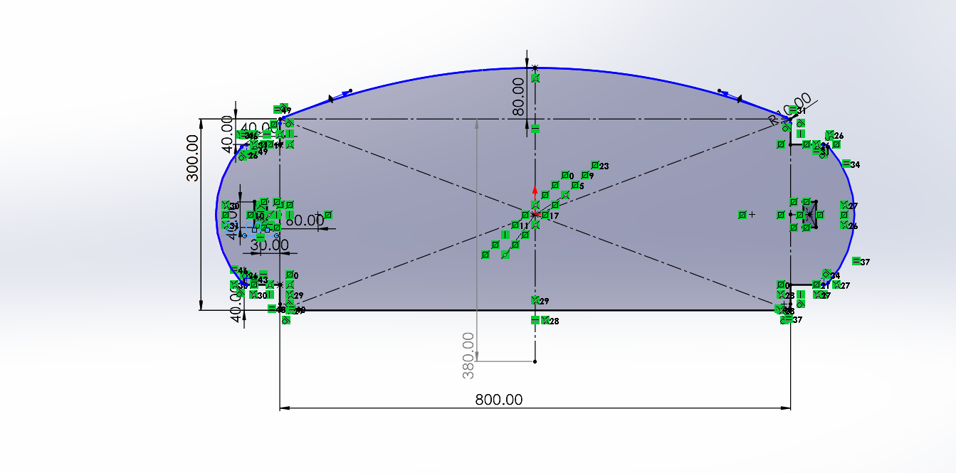
To create this design, I used the Mirror feature in SolidWorks. This allowed me to model one side of the board and then mirror it, ensuring that both sides were perfectly symmetrical. This approach saved time and helped maintain design consistency, especially for features that needed to be aligned on both sides.
I used the Extruded Boss/Base feature to give the board an 18 mm thickness, matching the MDF I planned to use.
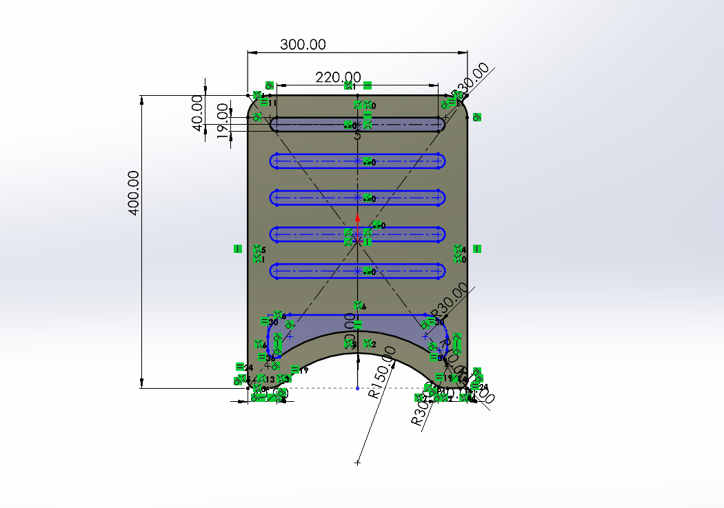
I created a slot in the design and then used the Linear Pattern feature to duplicate it, making a total of 5 evenly spaced slots.
I then applied the same 18 mm thickness to match the rest of the design.
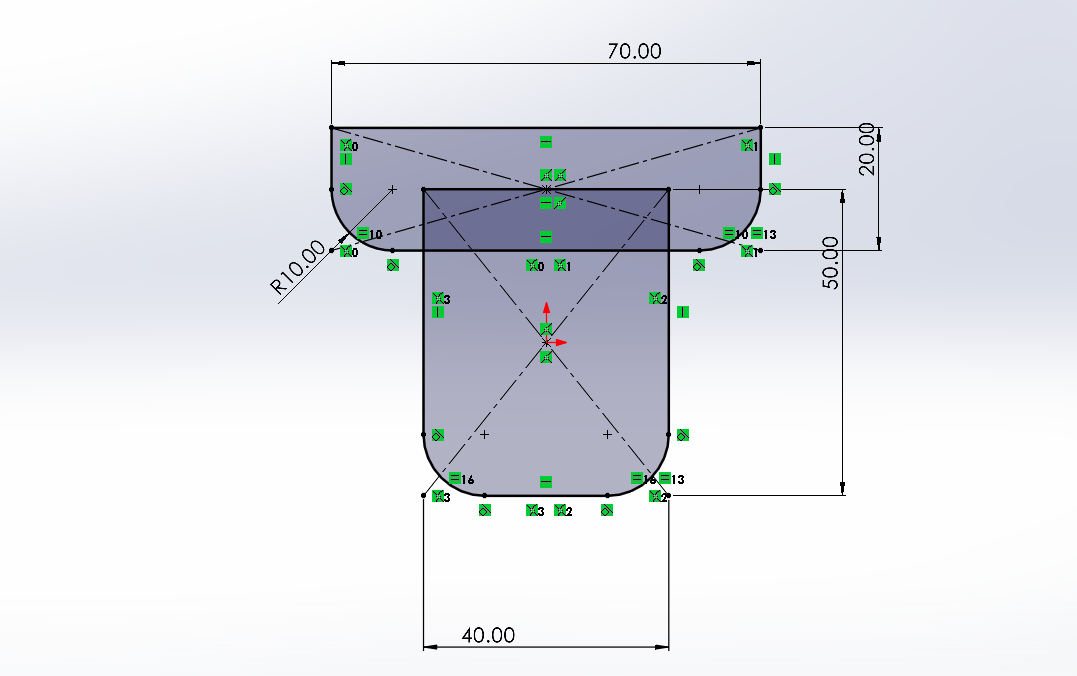
Next, I designed another part that will hold the two main pieces together, ensuring proper alignment and stability in the final assembly.

Preparation for Milling
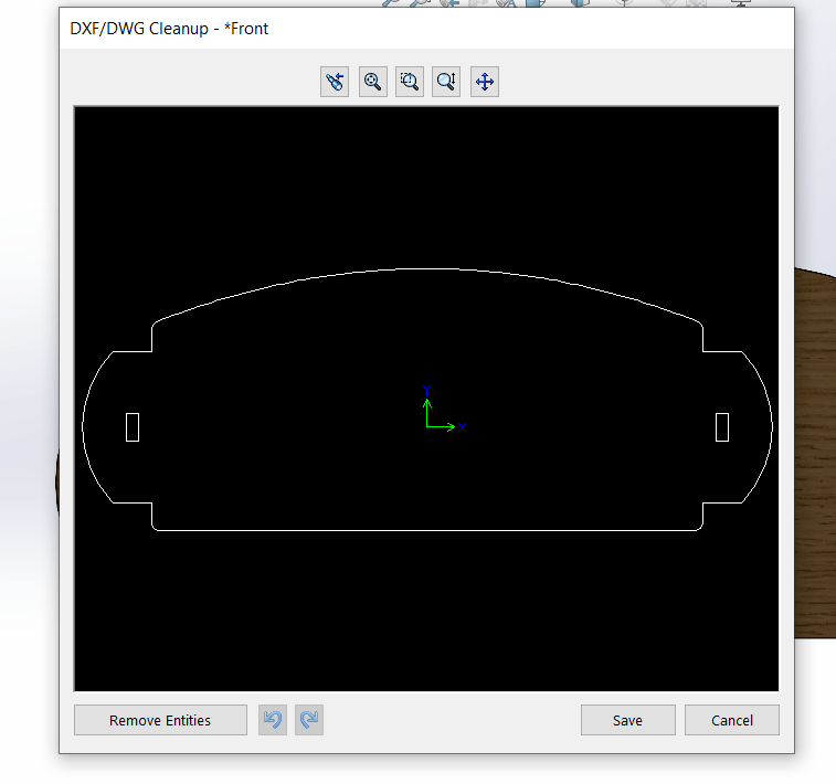
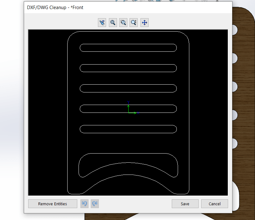
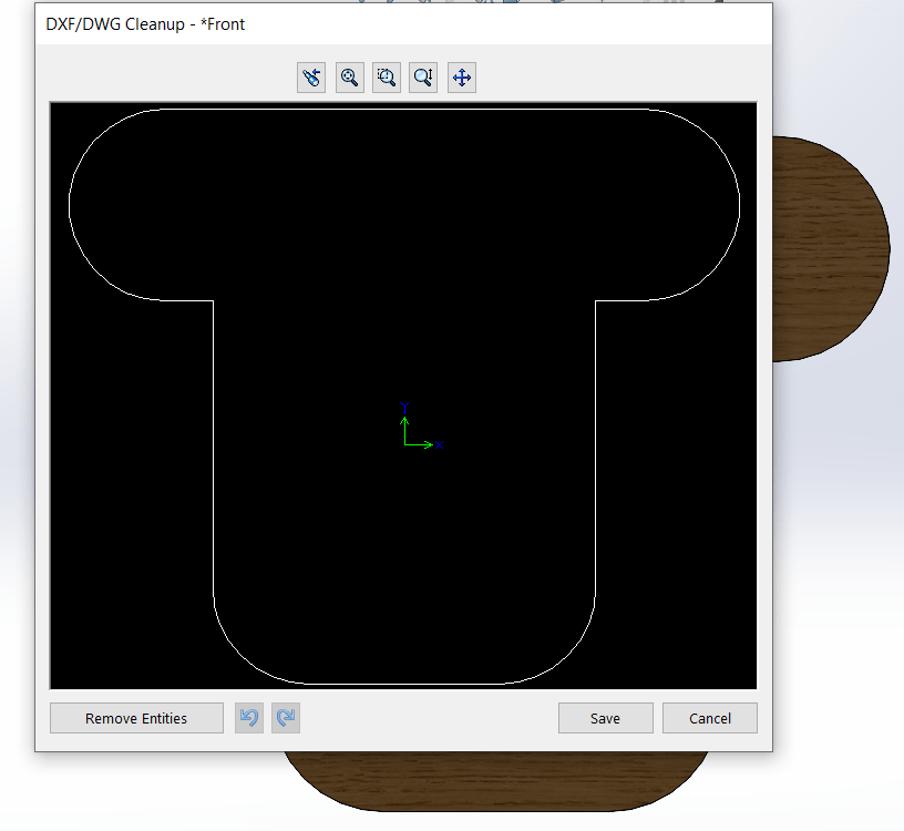
Before milling, The design looked good, so I exported the 2D drawings as DXF files, ready for CNC processing.
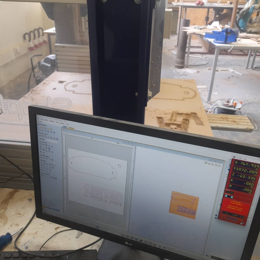
Machining Process
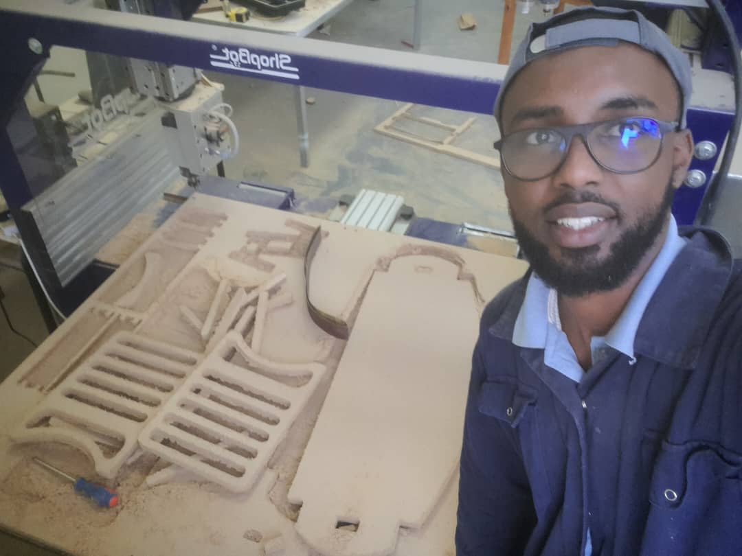
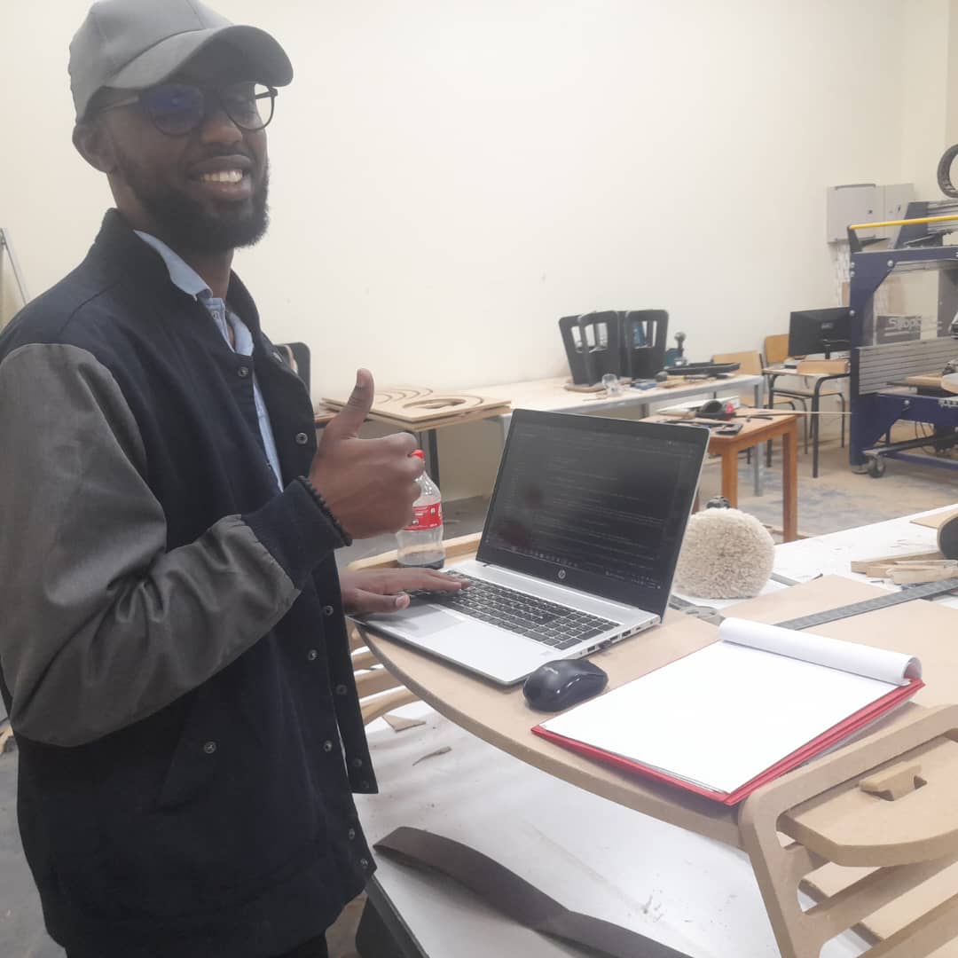
I used VCarve to prepare the toolpaths and arrange the layout for cutting. After that, I set the origin and controlled the milling process using the ShopBot Control System Interface.
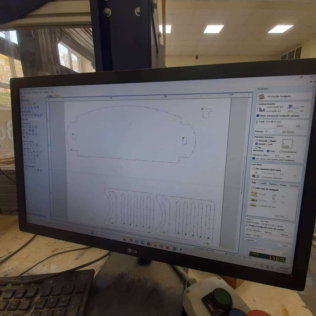
In VCarve, I imported the DXF files of my parts and prepared the toolpaths needed for milling. I adjusted the settings to match the desired cuts for the final product.
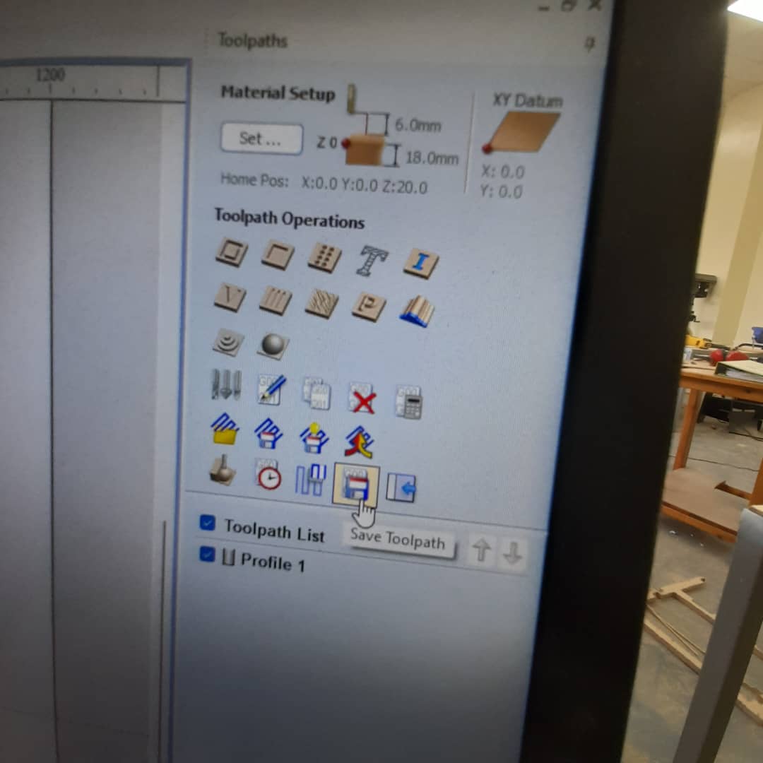
After setting the appropriate parameters, I saved the toolpaths to be used on the CNC machine.
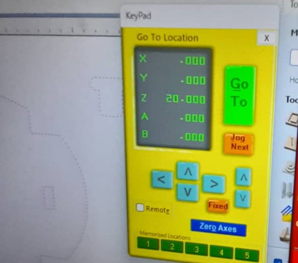
I then set the X, Y, and Z zeros on the CNC machine to align the tool with the origin point of the material, ensuring accurate cutting.Then move the Z to 20 for a smooth start.
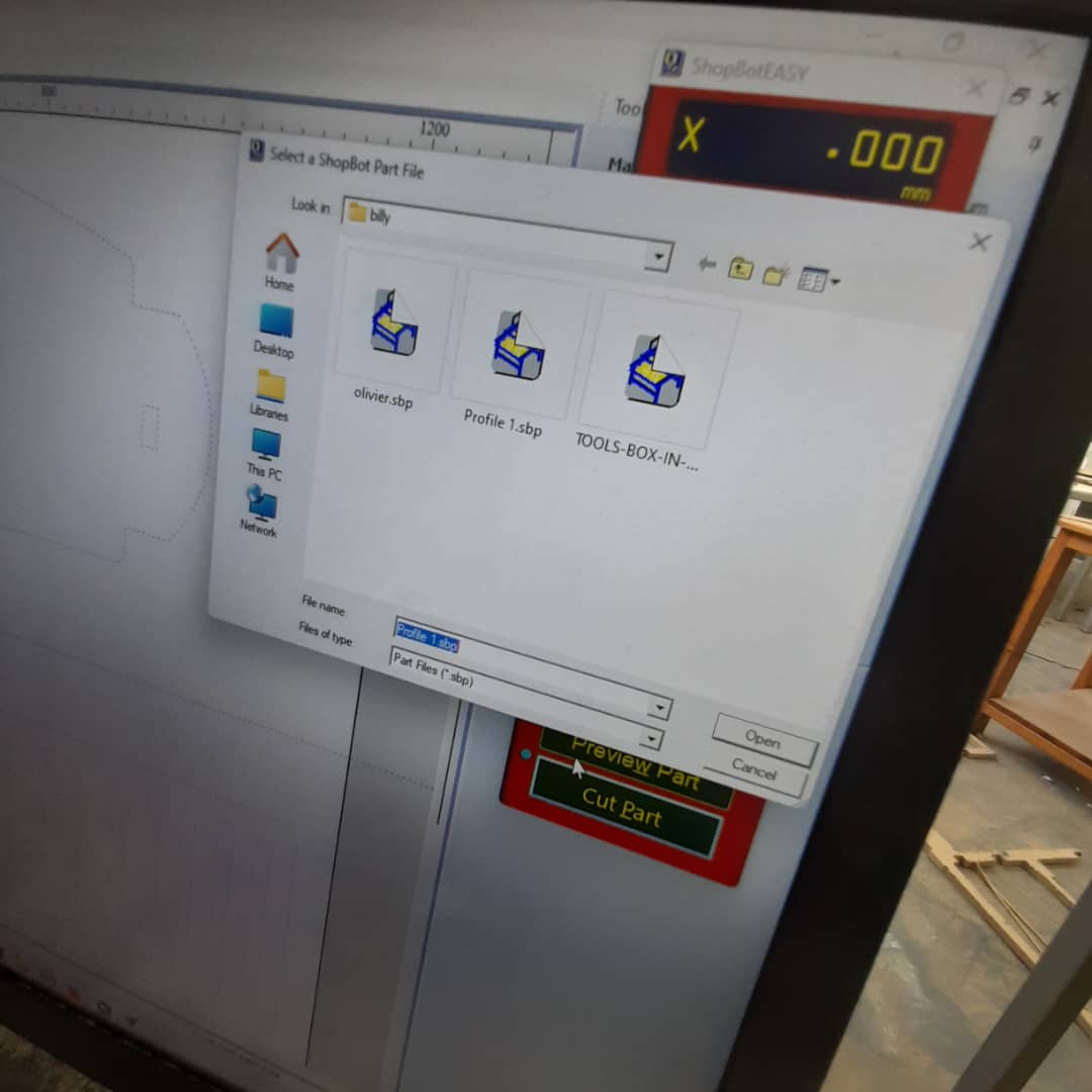
Next, I clicked “Cut Part” on the CNC interface and opened the saved toolpath file to start the cutting process.
Then, I started the cutting process, carefully monitoring the machine to ensure everything ran smoothly.
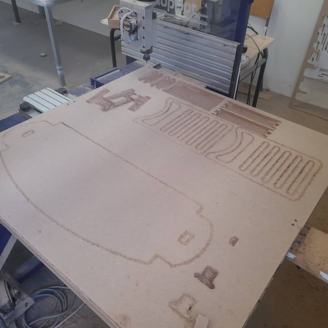
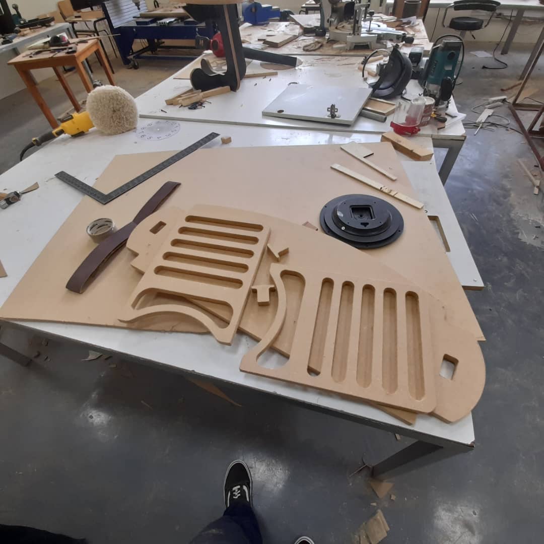
The image shows the finished parts after cutting, still attached to the MDF sheet before removal.
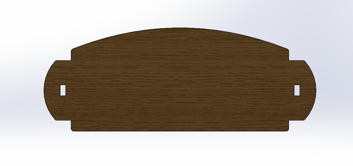
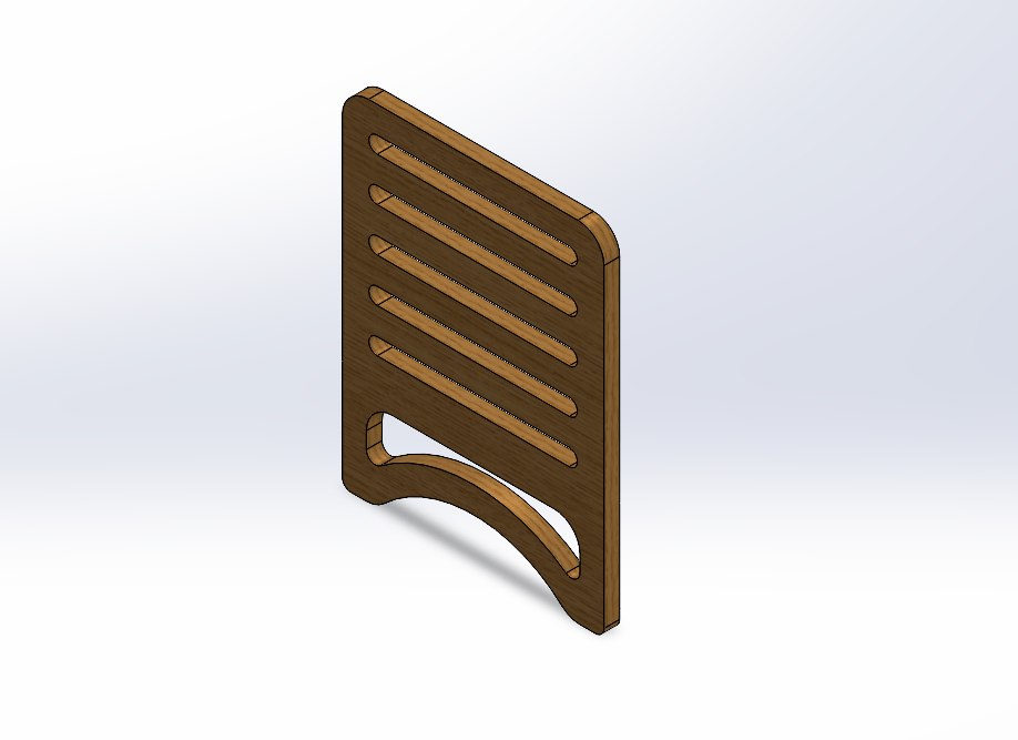
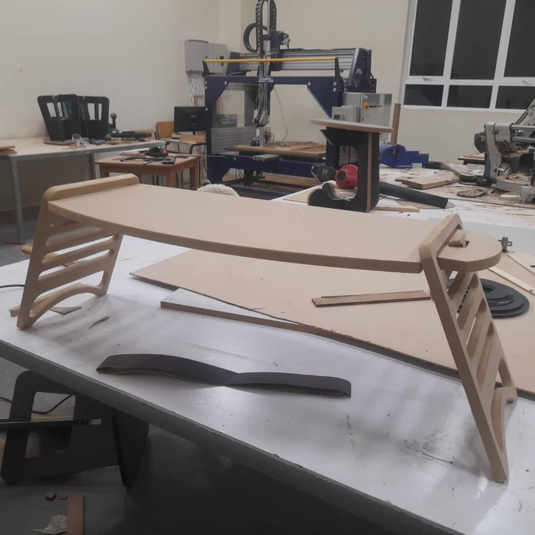
The milling went smoothly, and all parts came out clean. I sanded the edges, assembled the pieces, and was satisfied to see the stand working just as expected — strong, stable, and adjustable.
Here are the smoothed parts, prepared and ready for assembly.
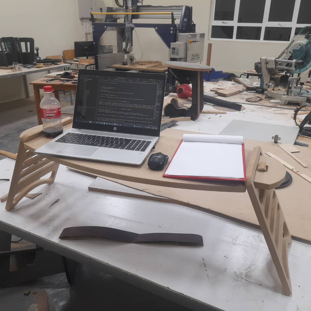
Here is the final assembly of the parts after fitting them together.
Reflection and Takeaways
- Start with visual research, even if you don’t have exact dimensions — inspiration can come from anywhere.
- Always double-check your measurements and ensure all parts will fit within your material size and thickness.
Design files
- download file (part1)
- download file (paer1,dxf)
- download file (part2)
- download file (paer2,dxf)
- download file (part3)
- download file (paer3,dxf)