Mechanical Design, Machine Design
Mechanical Design (part 1 of 2)
- Group assignment:
- Design a machine that includes mechanism + actuation + automation + application
- Build the mechanical parts and operate it manually
- Document the group project
- Individual assignment:
- Document your individual contribution
- Group assignment:
- Actuate and automate your machine
- Document the group project
- Individual assignment:
- Document your individual contribution
#.Group assignment:
Group Work Reflection
Our group designed and built a 5-axis robotic arm aimed at demonstrating precise articulated movement, potentially applicable in lightweight pick-and-place automation, educational tools, or small-scale assembly tasks.
Here is the Group assignment(link)
#.Individual Assignment: My Contribution
As part of the Fab Academy’s mechanical and machine design assignment, our group was tasked with designing, building, and automating a functional machine. We chose to build a 5-axis robotic arm, which offered a challenging yet rewarding opportunity to explore motion mechanics, automation, and collaborative teamwork. The goal was to develop a machine that integrates mechanism, actuation, automation, and a clear application all within a short timeframe and using accessible tools like 3D printing, microcontrollers, and basic electronic components.
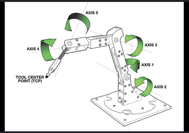
In the first phase of the assignment, Mechanical Design, we worked together to conceptualize the structure and motion requirements for the robotic arm. The team brainstormed possible configurations and degrees of freedom, eventually settling on a design that would allow the arm to perform complex movements across five axes.
My specific responsibility in this phase was contributing in the research, the design and 3D printing of the mechanical components.
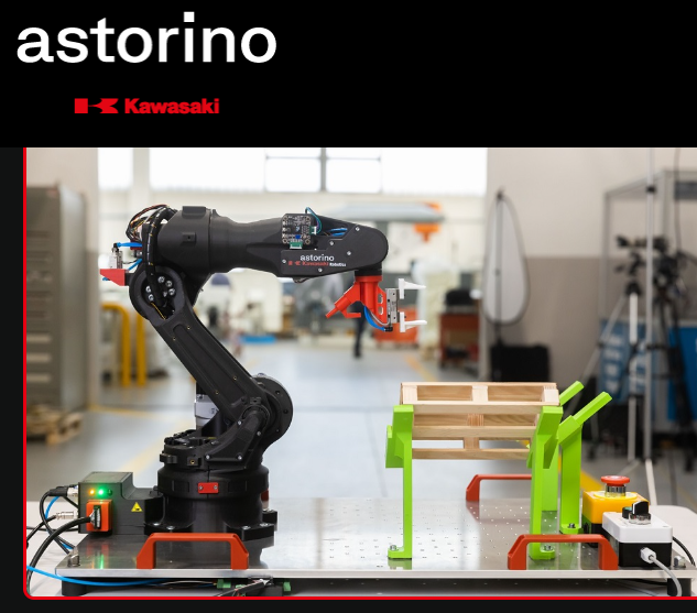
Kawasaki Robotics ASTORINO robot was the first arm i thougt for the project because it is a educational robot
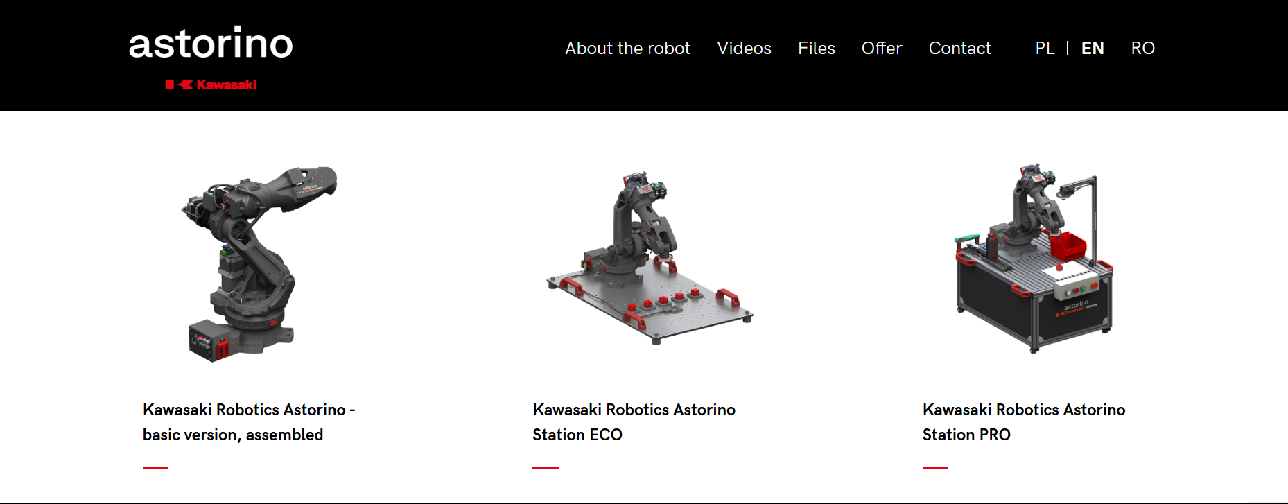
Here in there site where you can see them robots.
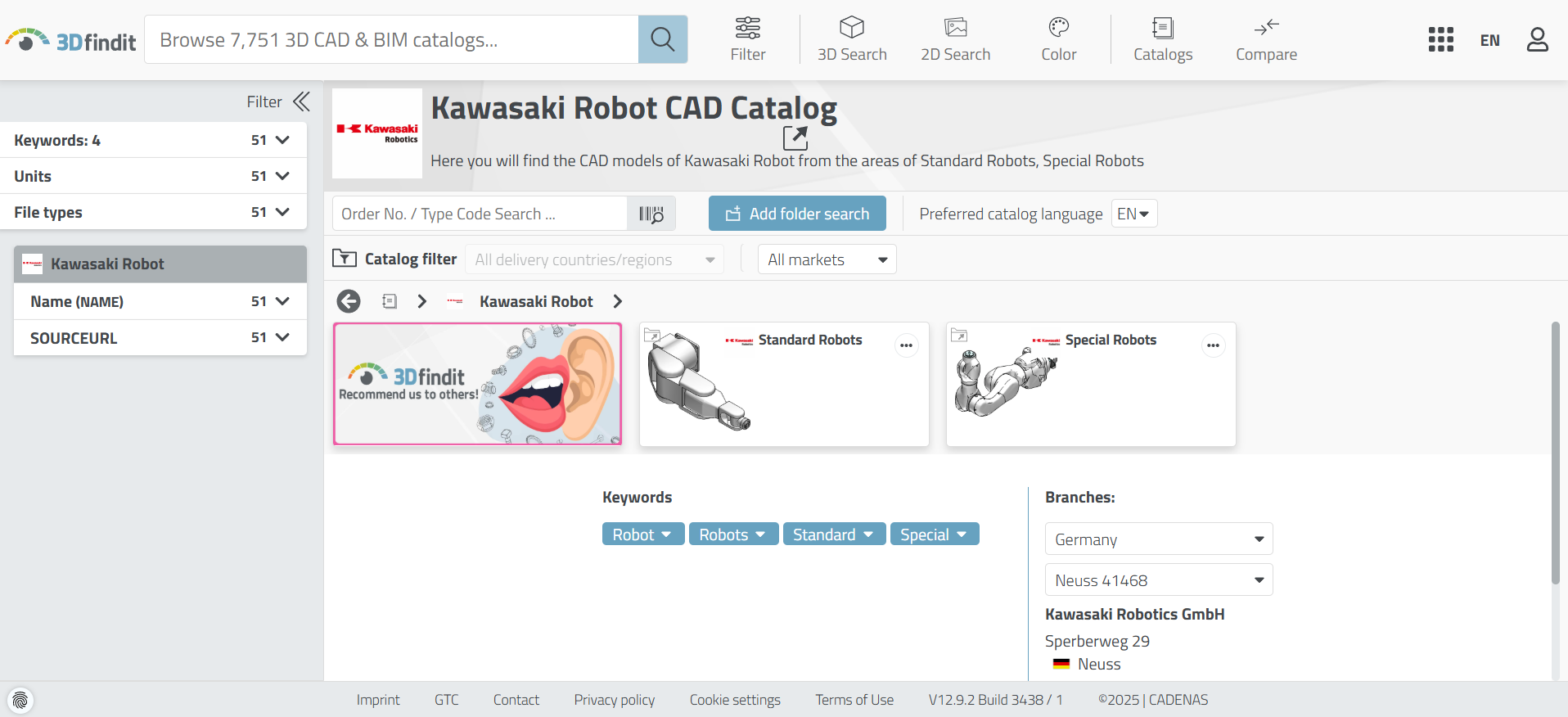
then i searched for Kawasaki CAD at 3Dfindit
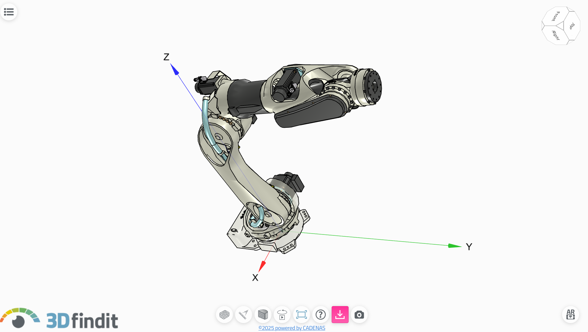
This was one of the robot i found but it was complicated depending on the the time we had for the project.

We used SolidWorks as our primary CAD tool to model the robotic arm’s base, joints, and motor housings. Early in the process, we encountered issues with tolerances in the 3D-printed parts; some connections were either too tight or too loose, which affected the fit and movement of components. We addressed this by adjusting tolerances in the design and reprinting the affected parts.
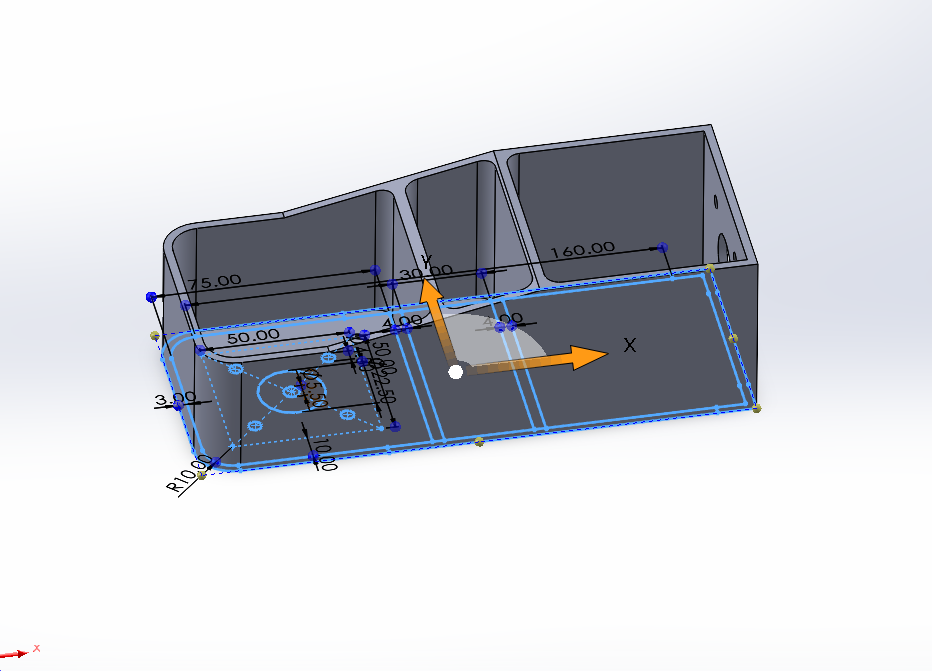
This is the one of the parts we used, and i was told to design it then print it
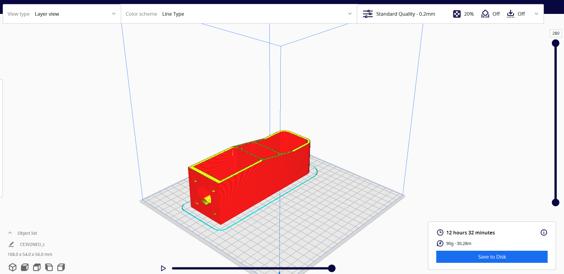
Slicing the part in ultimaker cura
Another major challenge we faced was structural overload. Initially, we underestimated the combined weight of the printed parts and the NEMA 17 stepper motors. This caused stress and instability in the arm’s structure, particularly at the joints. To fix this, we modified some part designs to reinforce weak areas and redistributed weight where possible. Through trial and error and with constant communication among the team, we successfully assembled a functioning mechanical prototype.
So we desided to use an open source (link) and edit the parts to our need.
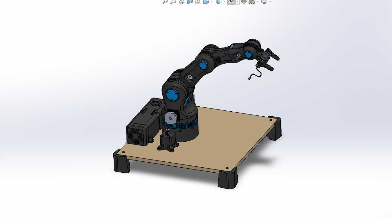
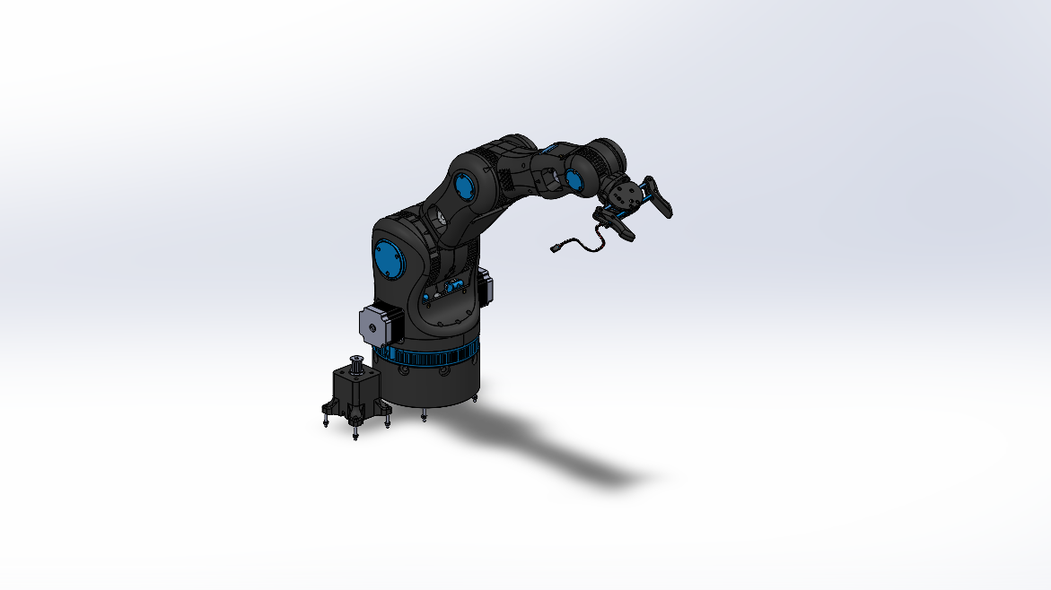
This was the image in SolidWorks of the design we were going to use.

This is all parts which made the assembly
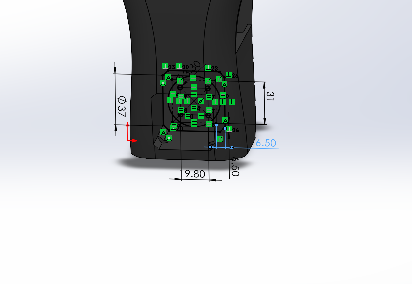
Editing where we will mount the stepper motors
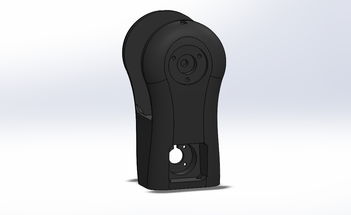
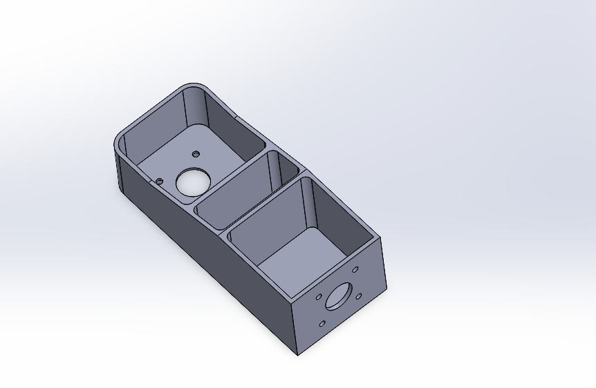
The final design
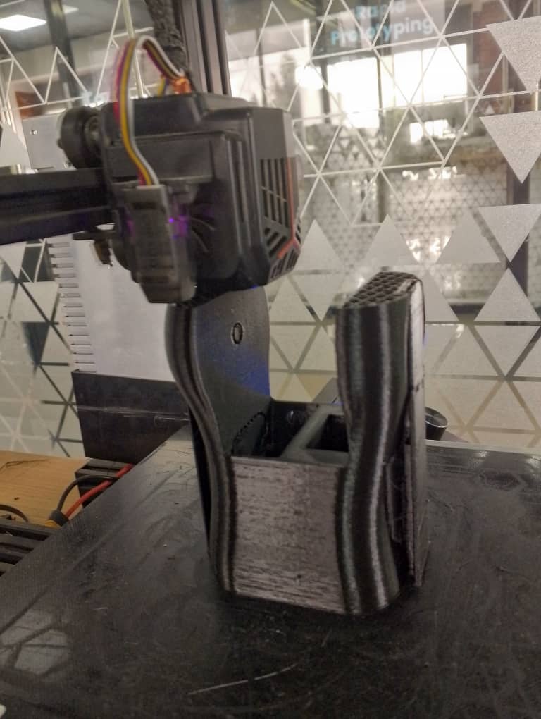
Printing the part
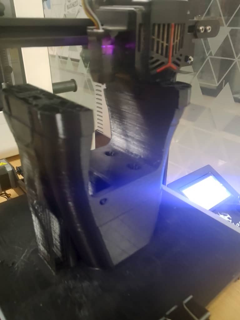
video of the printing part
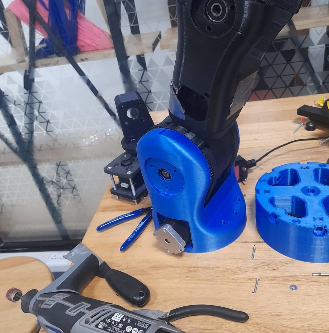
Assembling the parts.
Assembling the parts.
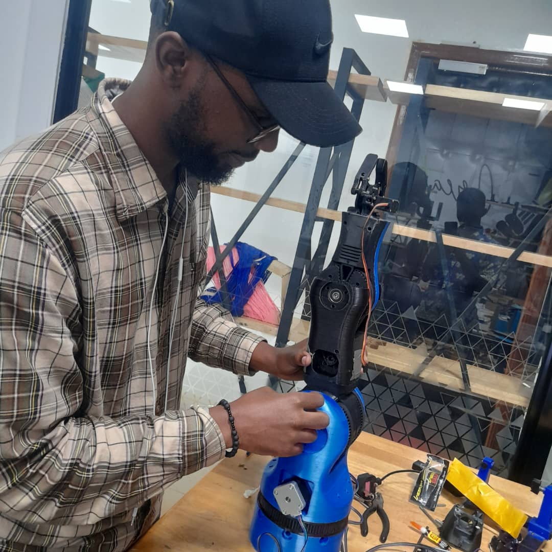
Assembling the parts.
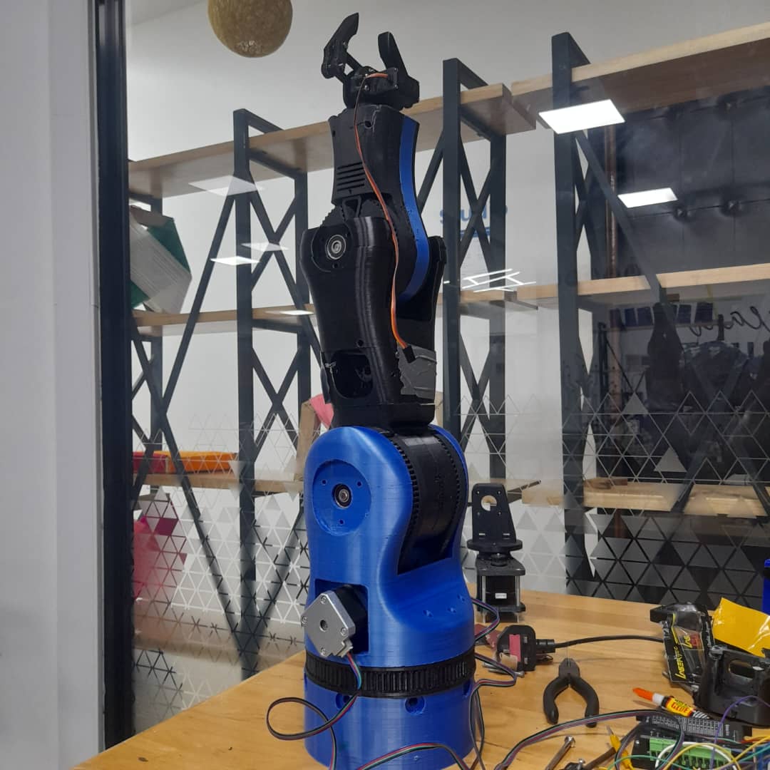
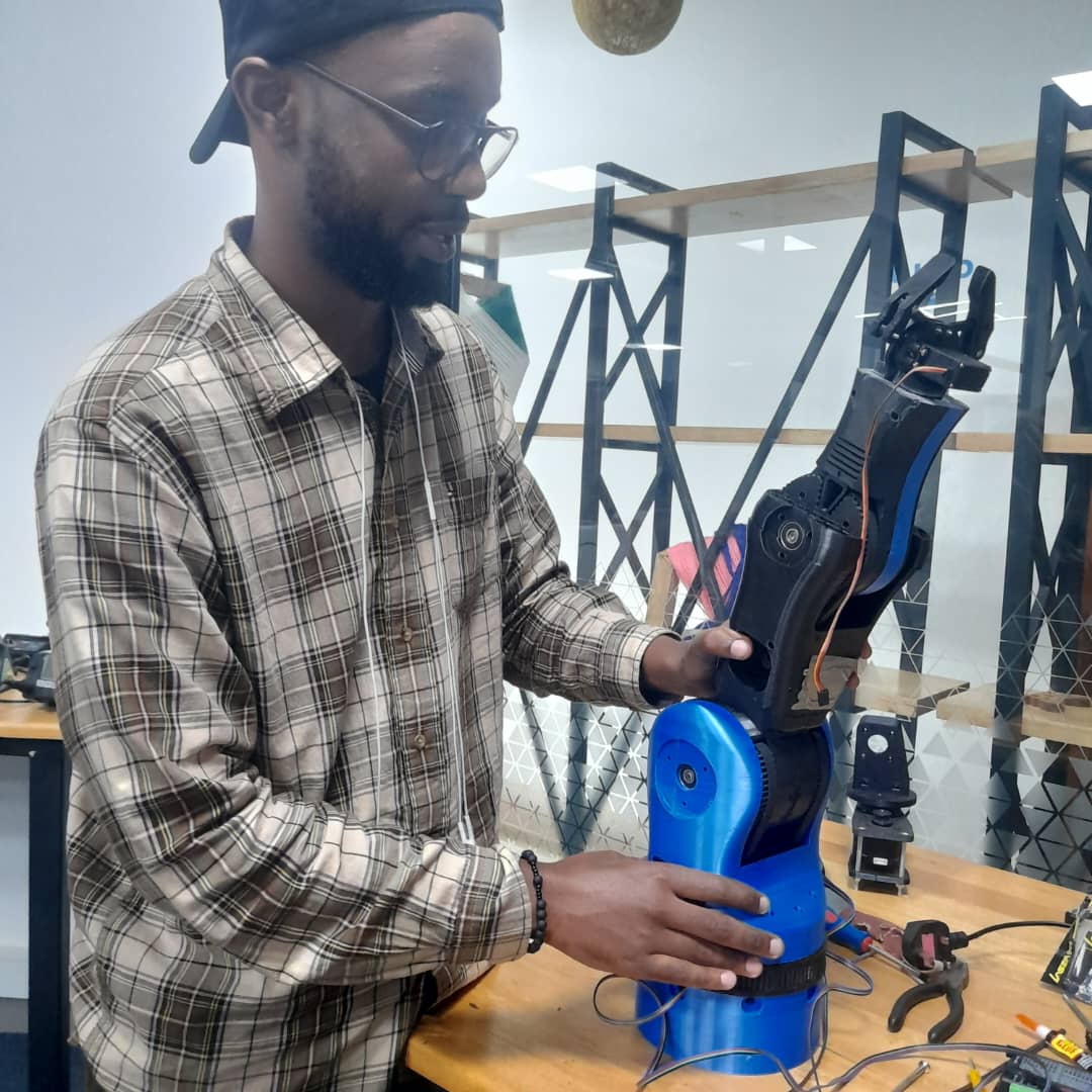
The final assembled robot
Through this project, I learned how to design mechanical systems that work in real-world conditions, not just on screen. I gained hands-on experience in troubleshooting tolerance and load issues and learned the importance of accounting for material properties and motor weight during design. Working in a team setting helped me understand how to coordinate across disciplines design, electronics, and programming and how to adapt when one part of the system influenced another. The experience also showed me the importance of iteration, testing, and open communication in the design process. Overall, this was a valuable experience in collaborative machine-building and prototyping.