For this week's group assignment, we measured the power consumption of an output device. This involved using tools such as multimeters and power analyzers to monitor the current and voltage levels of the device during operation. Our findings were documented on the group work page, and I reflected on what I learned on my individual page.
For the individual assignment, I added an output device to a microcontroller board that I had designed and programmed it to perform a specific task. This process involved integrating the output device, writing code to control its behavior, and testing the setup to ensure proper functionality. It allowed me to apply the knowledge gained from the group assignment and further develop my skills in output device integration and microcontroller programming.
Group Assignment
For the group assignment, we measured the power consumption of an output device. This involved using tools such as multimeters and power analyzers to monitor the current and voltage levels of the device during operation. Our findings were documented on the group work page, and I reflected on what I learned on my individual page.
For the individual assignment, I decided to build upon the circuit I designed during Week 09 - Input Devices. Since I had already connected a sound sensor, I chose to use a 16x4 LCD module as an output device to measure and display the highest recorded sound intensity. This allowed me to fulfill the requirement to "Add an output device to a microcontroller board you've designed and program it to do something."
The process involved connecting the LCD module to the appropriate pins on my development board, writing code to read the sound sensor's output, and programming the LCD to display the maximum sound intensity recorded. By integrating the LCD module, I was able to visualize the sound levels in real-time and enhance the functionality of my circuit. This assignment provided valuable experience in combining input and output devices to create a complete system.
Understanding Output Devices
Output devices are components or peripherals that allow a system, such as a microcontroller or computer, to communicate information to the external environment. These devices play a crucial role in enabling interaction between digital systems and the physical world by converting processed data into a human-readable or actionable form.
Examples of Output Devices: Common output devices include LEDs, buzzers, motors, and display modules such as LCDs and OLEDs. These devices are used to provide visual, auditory, or mechanical feedback based on the system's operation.
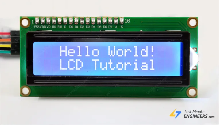
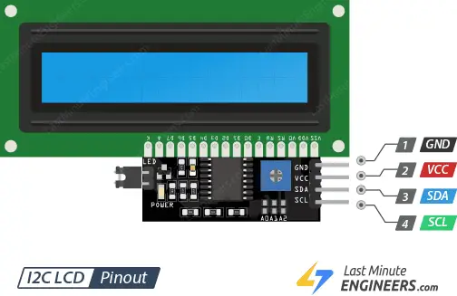
I2C LCD Module: The I2C (Inter-Integrated Circuit) LCD module is a type of output device that simplifies the process of interfacing an LCD screen with a microcontroller. Traditional LCDs require multiple pins for communication, but the I2C module reduces this to just two pins: SDA (Serial Data) and SCL (Serial Clock). This makes it ideal for projects with limited GPIO pins.
What is I2C? I2C is a communication protocol that allows multiple devices to communicate over a two-wire bus. It is widely used in embedded systems due to its simplicity and efficiency. The protocol uses a master-slave architecture, where the master device (e.g., a microcontroller) controls the communication, and the slave devices (e.g., sensors or displays) respond to the master's requests.
Why Use I2C for the LCD Screen? The I2C protocol significantly reduces the number of pins required to interface with the LCD, making it easier to connect and manage. Additionally, it allows multiple devices to share the same bus, enabling more complex systems without increasing pin usage. This makes the I2C LCD module a versatile and efficient choice for displaying information in embedded projects.
In summary, output devices like the I2C LCD module are essential for presenting information from a system. The I2C protocol simplifies communication and reduces hardware complexity, making it a popular choice for modern embedded applications.
LCD Display
For this project, I used an LCD display to show the maximum recorded value from the microphone sensor and the value of an RFID tag. The LCD display serves as an output device, providing a clear and real-time visualization of the data captured by the sensors.
The LCD display is connected to the microcontroller via an I2C interface, which simplifies the wiring by using only two pins: SDA (Serial Data) and SCL (Serial Clock). This setup allows the microcontroller to send data to the LCD efficiently while leaving other GPIO pins available for additional components.
In this project, the microphone sensor captures sound levels, and the microcontroller processes the analog signal to determine the maximum recorded value. Simultaneously, an RFID reader is used to scan RFID tags, and the unique identifier (UID) of each tag is read. The microcontroller then sends both the maximum sound level and the RFID tag value to the LCD display for visualization.
The LCD display alternates between showing the maximum sound intensity and the RFID tag value, providing a user-friendly interface for monitoring both data points. This integration of input and output devices demonstrates the versatility of embedded systems in handling multiple tasks simultaneously.
By combining the microphone sensor, RFID reader, and LCD display, I was able to create a functional system that captures, processes, and displays data in real-time. This project highlights the importance of output devices in presenting information and enhancing the usability of embedded systems.
Code
Here is the code I used to read the RFID UID and microphone sound level, and display them on the LCD module:
#include <Wire.h>
#include <LiquidCrystal_I2C.h>
#include <SPI.h>
#include <MFRC522.h>

// LCD setup
LiquidCrystal_I2C lcd(0x27, 16, 2); // I2C address 0x27, 16 columns, 2 rows

// RFID setup
#define RST_PIN D3
#define SS_PIN D2
MFRC522 rfid(SS_PIN, RST_PIN);

// Microphone setup
int micPin = D1; // Analog pin connected to the microphone module
int micValue = 0;

void setup() {
  pinMode(micPin, INPUT);
  // Initialize LCD
  lcd.init();
  lcd.init();
  lcd.backlight();
  lcd.print("Initializing...");

  // Initialize RFID
  SPI.begin();
  rfid.PCD_Init();

  // Initialize Serial
  Serial.begin(9600);
  lcd.clear();
  lcd.print("Ready");
  delay(1000);
}

void loop() {
  // Read microphone value
  micValue = analogRead(micPin);

  // Display microphone value on LCD
  lcd.clear();
  lcd.setCursor(0, 0);
  lcd.print("Mic Value:");
  lcd.setCursor(0, 1);
  lcd.print(micValue);
  delay(500);

  // Check for RFID card
  if (rfid.PICC_IsNewCardPresent() && rfid.PICC_ReadCardSerial()) {
  lcd.clear();
  lcd.setCursor(0, 0);
  lcd.print("RFID UID:");
  lcd.setCursor(0, 1);

  // Print UID to LCD
  for (byte i = 0; i < rfid.uid.size; i++) {
    lcd.print(rfid.uid.uidByte[i] < 0x10 ? "0" : "");
    lcd.print(rfid.uid.uidByte[i], HEX);
    if (i != rfid.uid.size - 1) lcd.print(":");
  }
  delay(3000);

  // Halt RFID card
  rfid.PICC_HaltA();
  }
}
This code initializes the LCD, RFID module, and microphone. It reads the microphone's analog value and displays it on the LCD. When an RFID card is detected, its UID is displayed on the LCD as well.
By running this code, I was able to observe both the microphone's sound levels and the RFID UID in real-time on the LCD module.
Demonstration
Here is a video demonstrating the microphone module in action, capturing sound levels and displaying the output:
This video showcases the setup and functionality of the microphone module, providing a visual representation of its performance.