2. Computer controlled cutting
Group assignment:
- Do your lab’s safety training
- Characterize your lasercutter’s focus, power, speed, rate, kerf, joint clearance and types.
- Document your work to the group work page and reflect on your individual page what you learned.
Link to Group page: can be found here
Individual assignments
- Design, lasercut, and document a parametric construction kit, accounting for the lasercutter kerf, which can be assembled in multiple ways.
- Cut something on vinyl cutter machine
I started by creating a rough sketch of what I wanted to create. It is two pieces kit that can be assembled in a sperical spaces and in a chain of spheres
I started by creating a tables of dimension. I used SolidWorks program on this assignment.
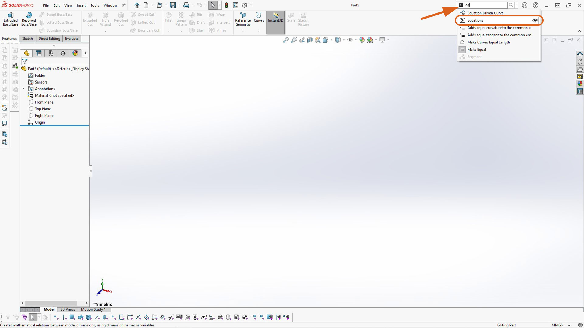
To create equation table in SolidWorks, you can use search command. I started by tyuping (search) and search bar. The priview will be visible as highlighted below
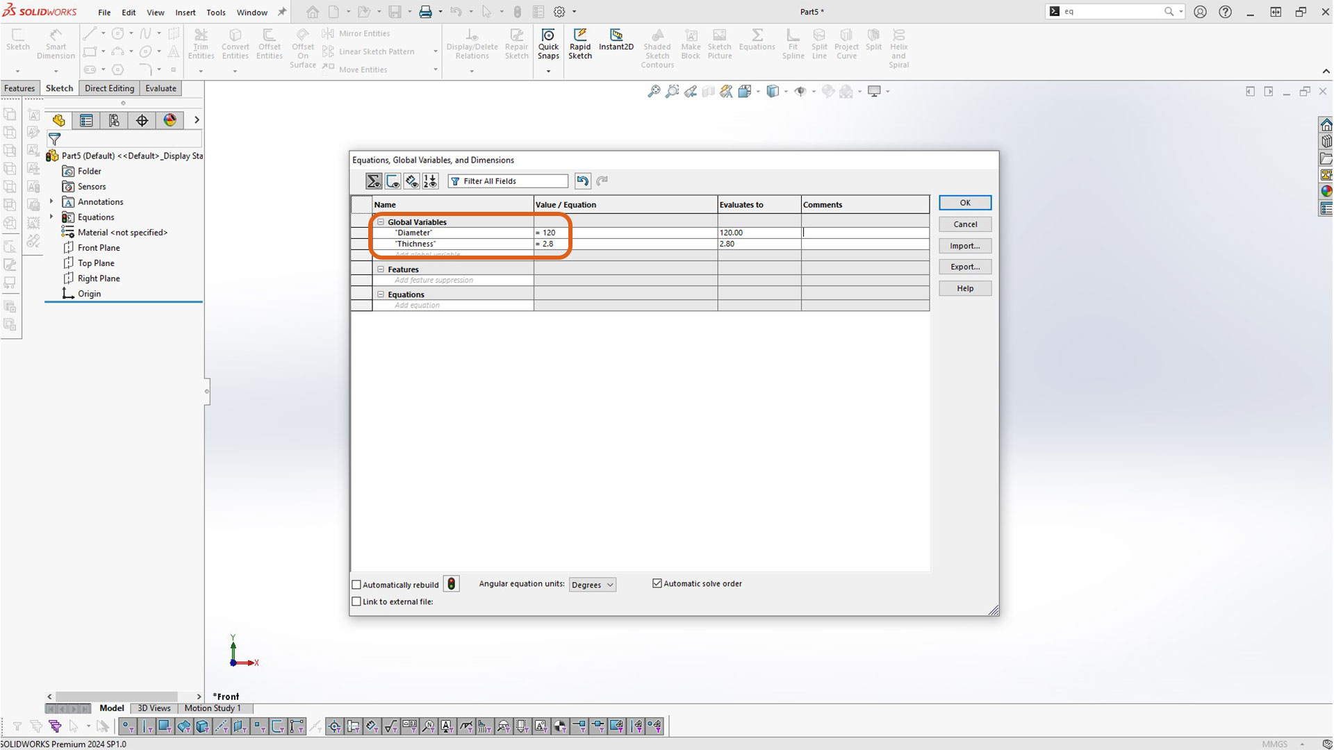
Afterwards, I created basic/principle variable: overal sphere diamenter and material thickness
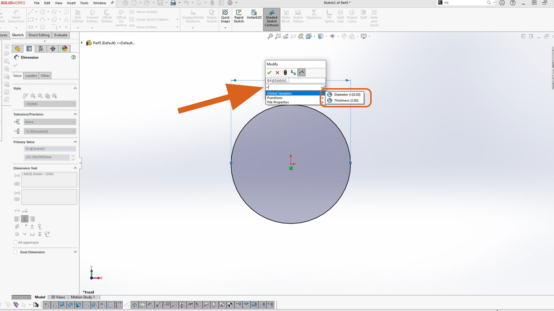
Nextly, I created circle which will in turn be the overal diameter of the sphere. To dimension it, I used equation parameter created early. You start by typing equal sign instead of number. All variable will be visible afterward.
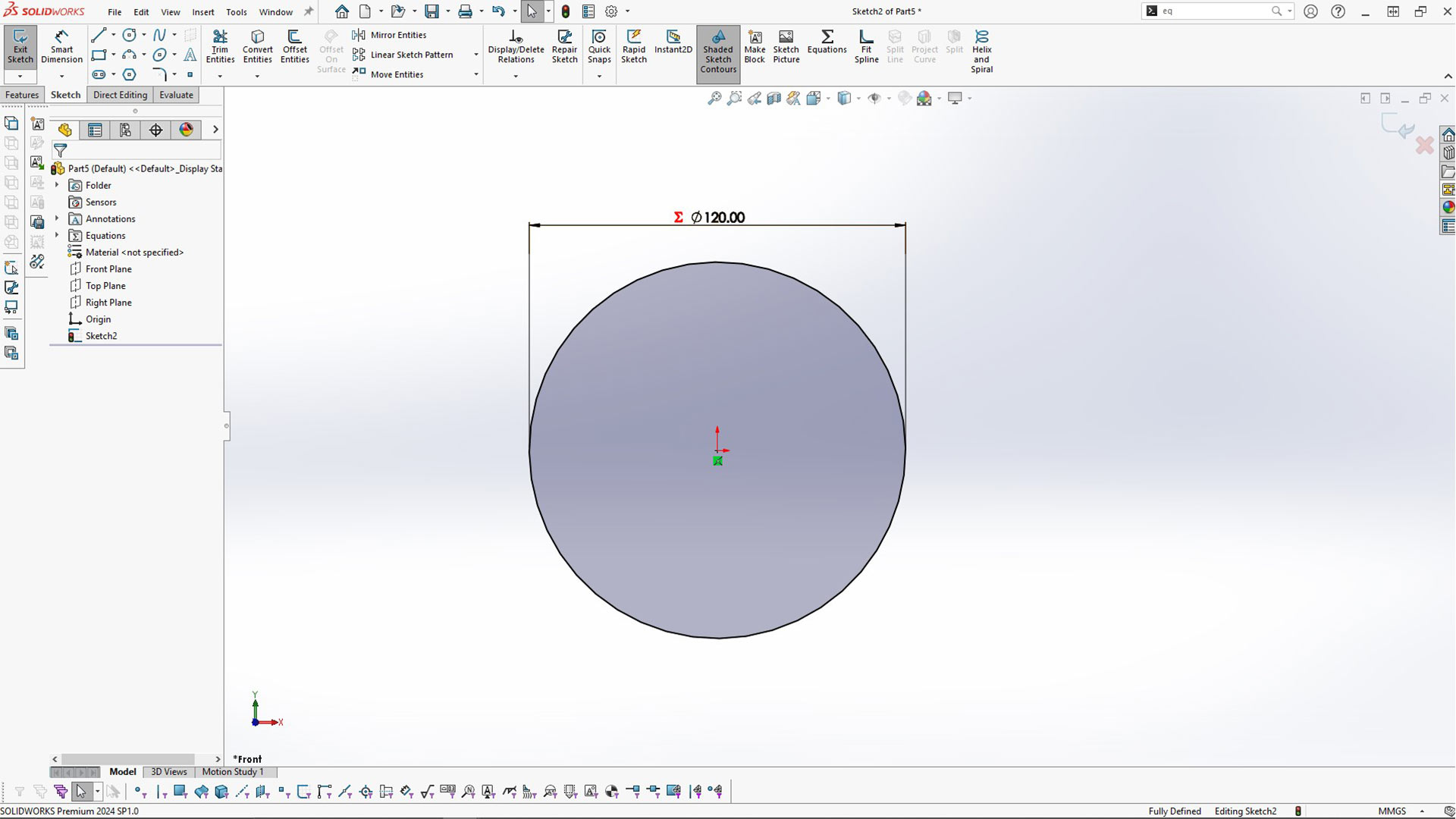
This is the output. The best part of using the global variable is that you can modify them from table and it will be automaticall be updated.
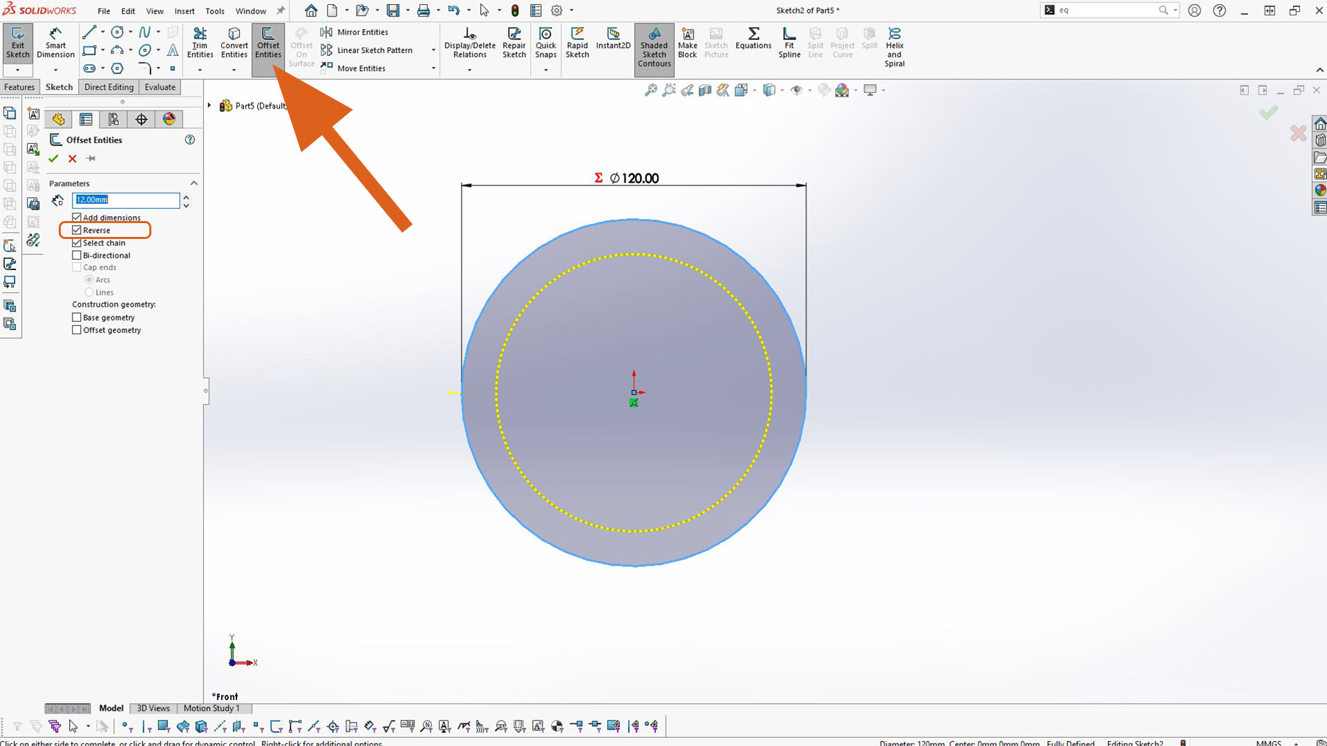
Then, I created offset circle of 12mm (inside offset). By default, the circle will be outside. Thus to reverse the direction, chech reverse icon as highlighted below in rectangular icon.
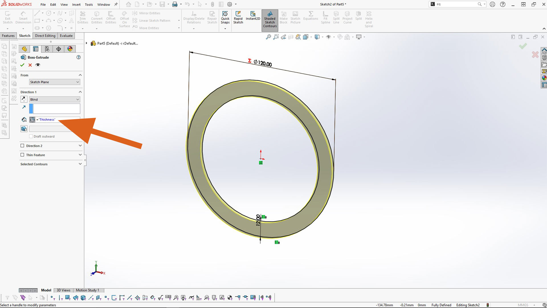
Next, I used Boss Extrude tool to create thichness. I indeed used global variable as well.
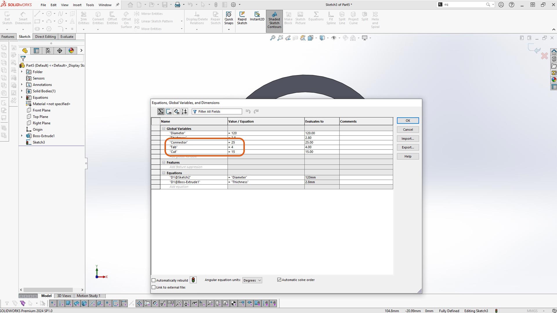
Next, I created the remaining global variables. To Edit table, you open equation again. The previous table created will be opened.
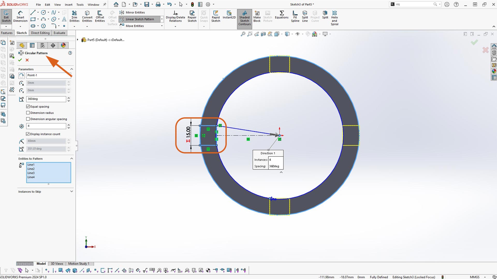
Afterwards, I sketched a rectangle. This is to slice the part in multiple sections. To create multiple copies, I used circular pattern. Ater creating patterns, I used Extrude cut to slice the body.
Next, I sketched a rectangular cut. I also used global variables.
I used circluar pattern and mirror pattern to create the other rectagles.
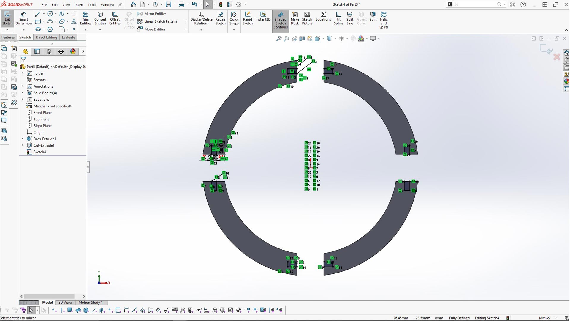
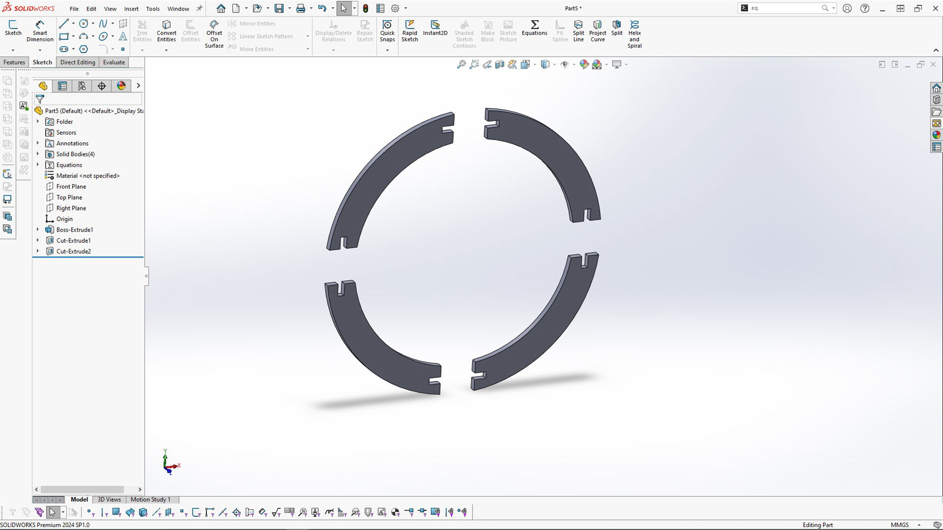
Then, I used Extrude cut again to cut all tabbs
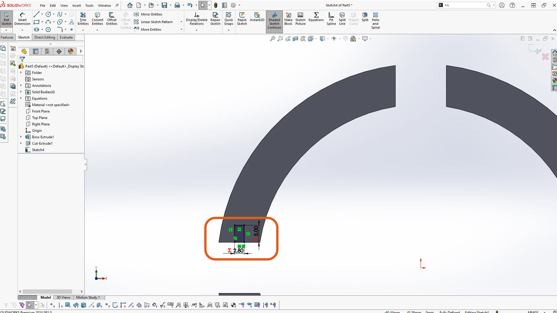
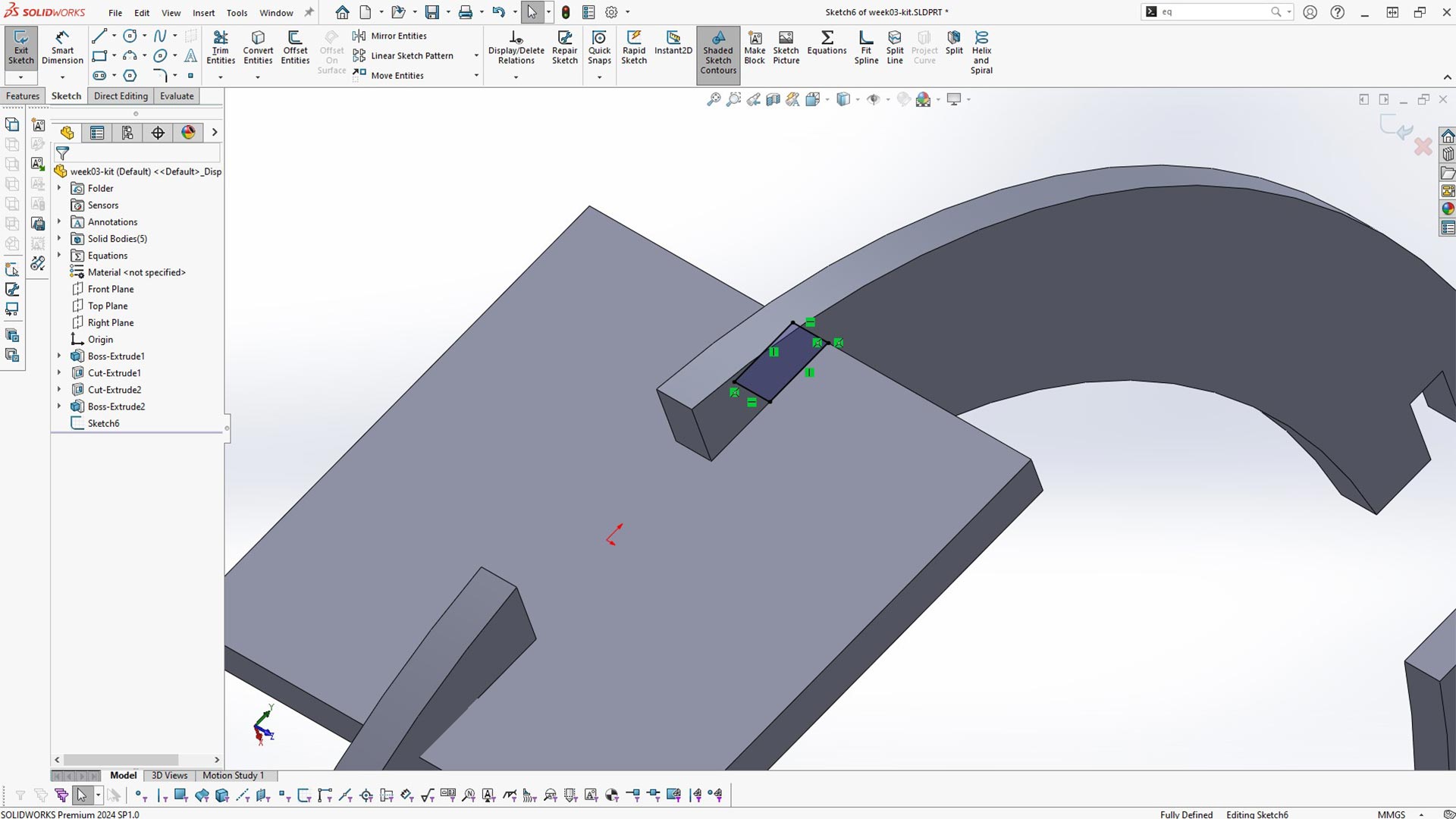
Next, I created connector by sketching a recagnle on the inside of the cubs as highlited. I made all sides of the rectangle equal by using equal relation.The rectagle is also sketched from cinter origin. This make it symmetrical from all sides.
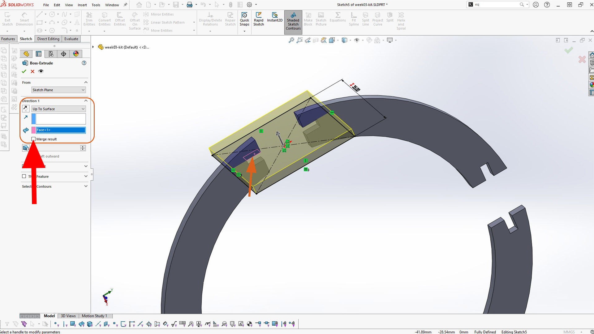
After creating the rectagle, I extruded to the surface. At this point, you can either use global variable of thichness or up surface in direction one as highlighted in rectangular icon below.
Notice: Uncheck merge result (as shown with red arrow) to avoid fusing bodies together. Because, every body need to be separate.
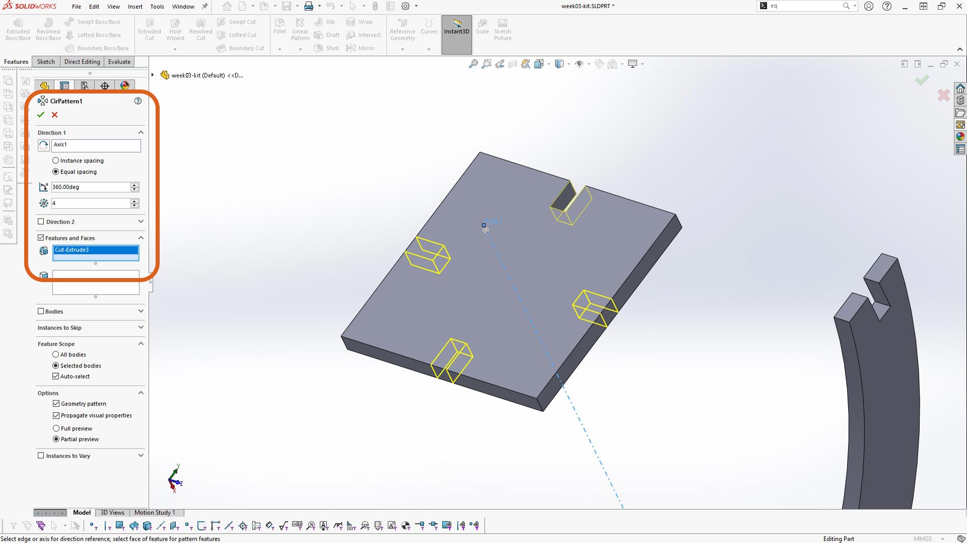
Next, I created a cut on connectors.
After creating the cut, I used circular pattern around center axis to remaing 4 slot cuts to
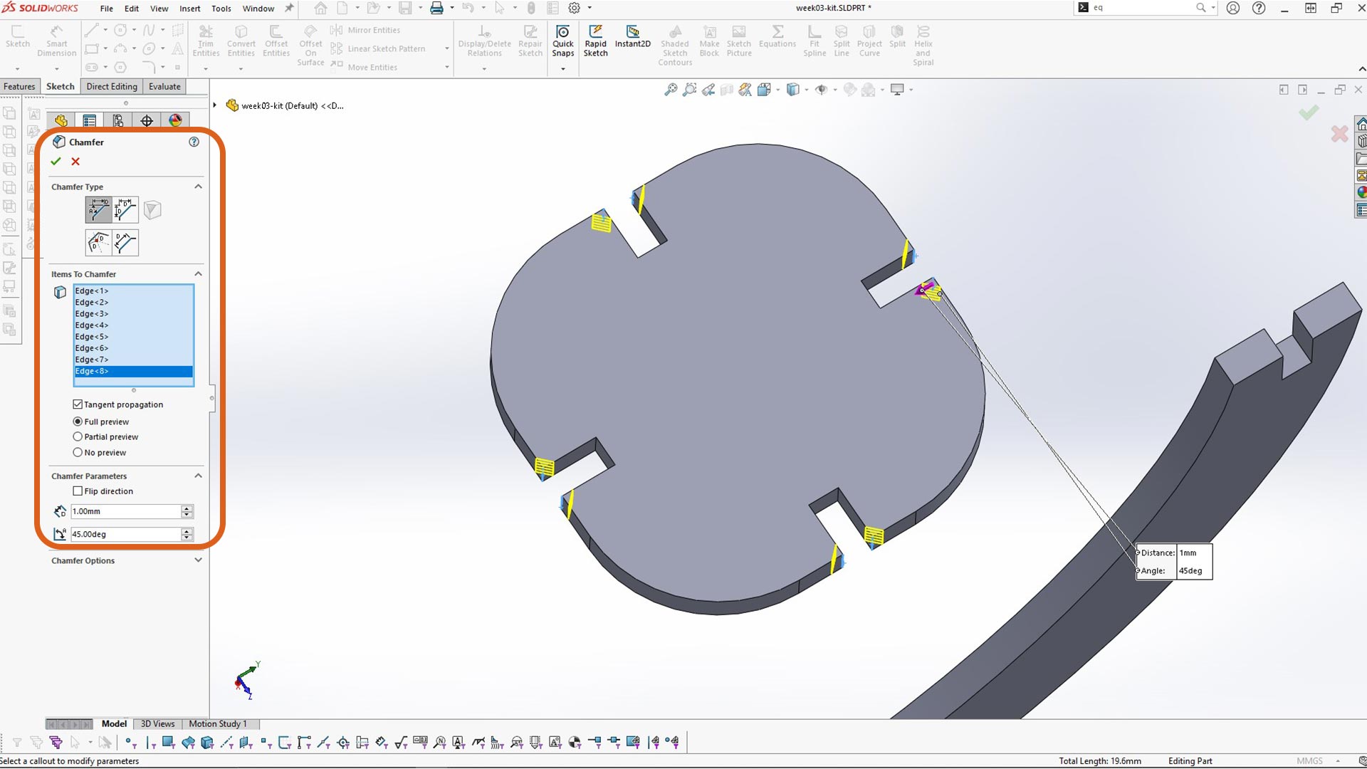
I added chamfer on every cut. This will ease the assembly process allowing parts to slide more easily into one another.
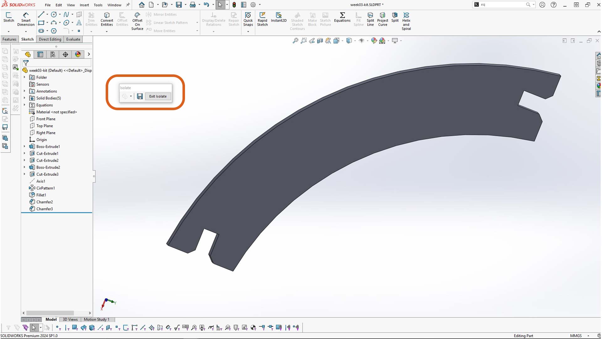
I also added chamfer on the second body. Using isolate tool, I was able to focus only on one body/part at a time.
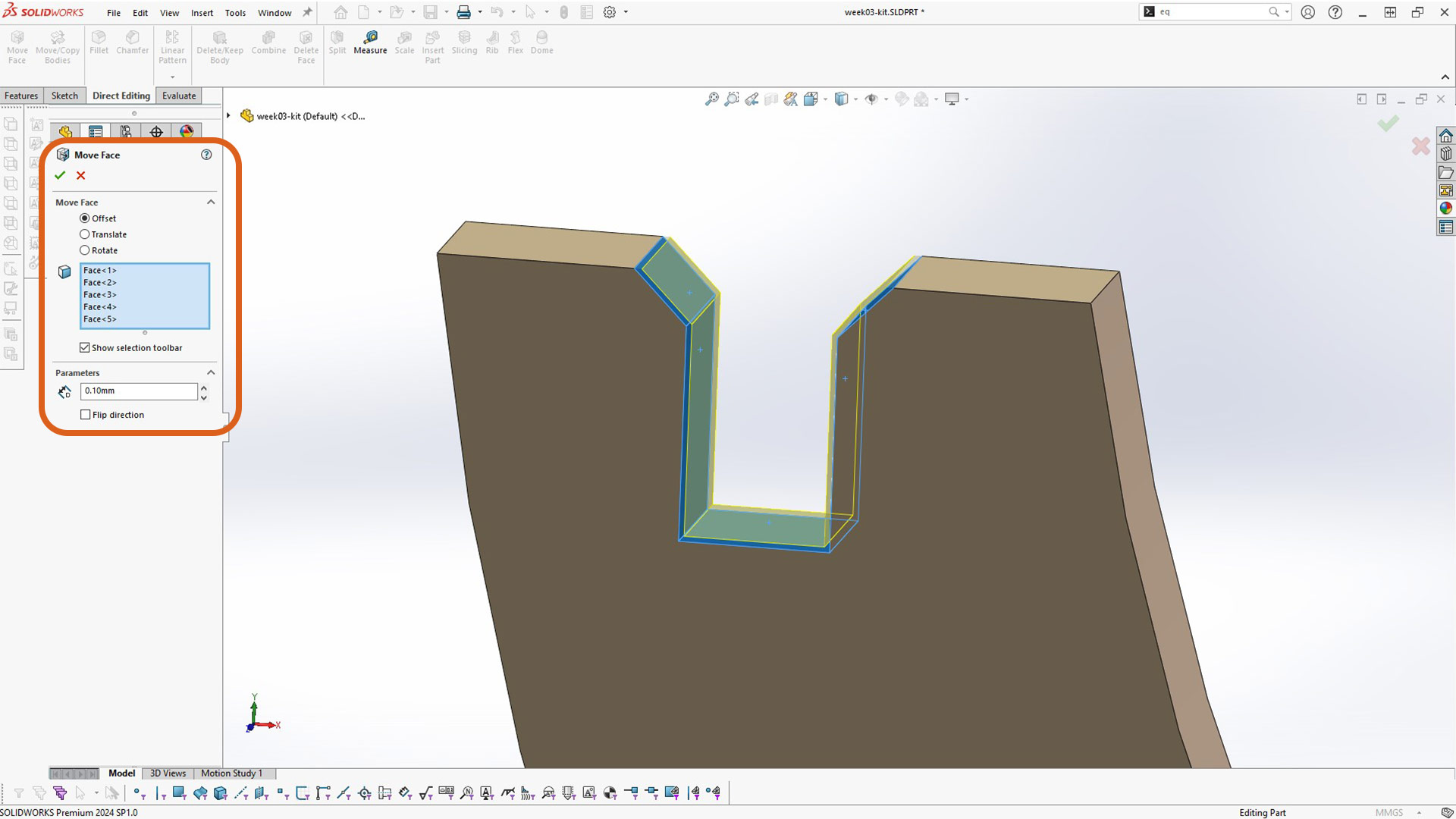
Nextly, I used move fave to reduce clearence. This value depends entirely on the clerare of laser cuter machine (kerfvalue). It is a good practice to print some some pieces to test it fast. Hence pieces need to fit together tightly without the use of any adhesive.
Then after that, I created assembly and insert the two parts.
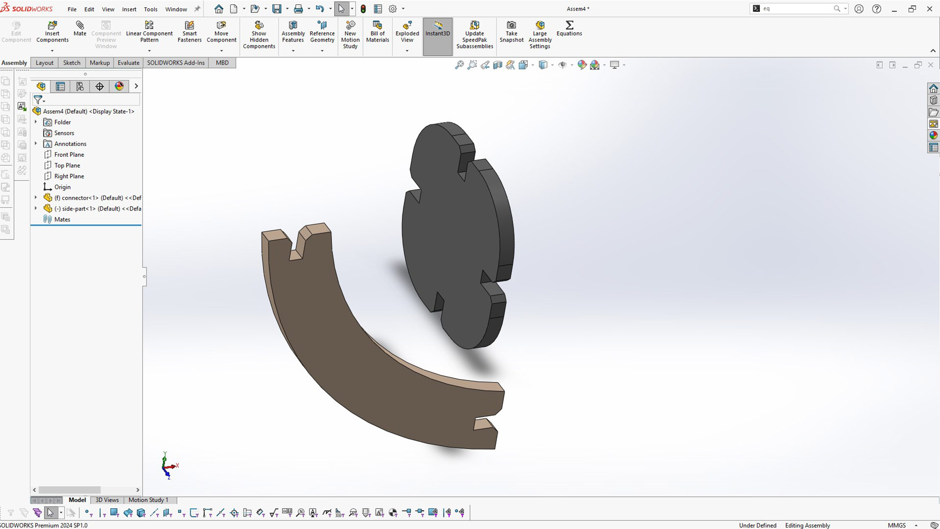
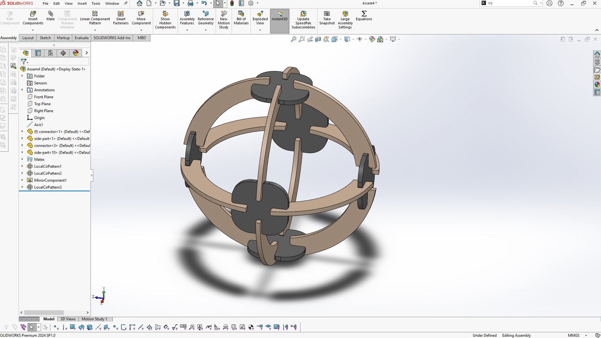
Assembly of single pairs
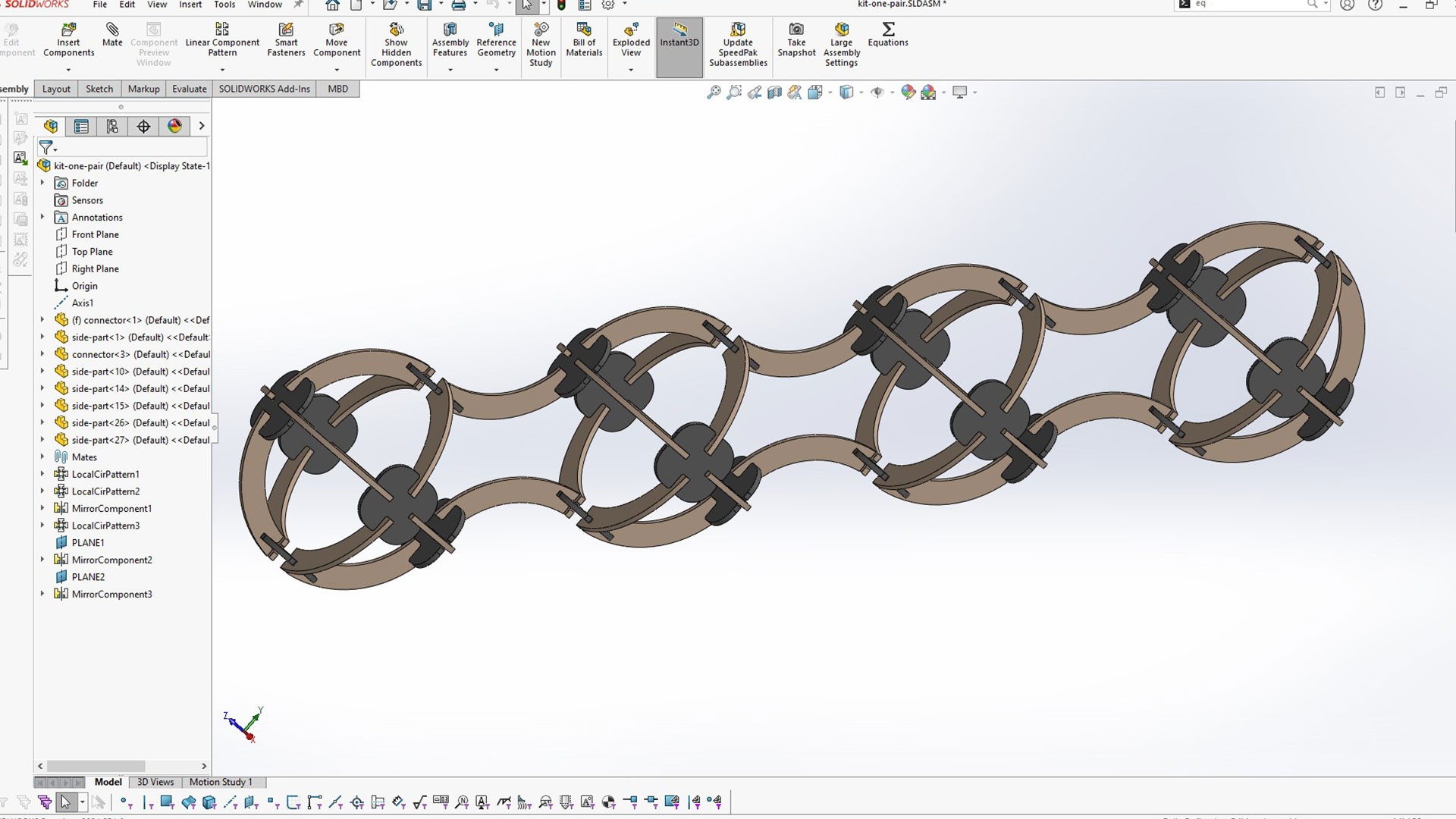
Assembly of 4 pairs
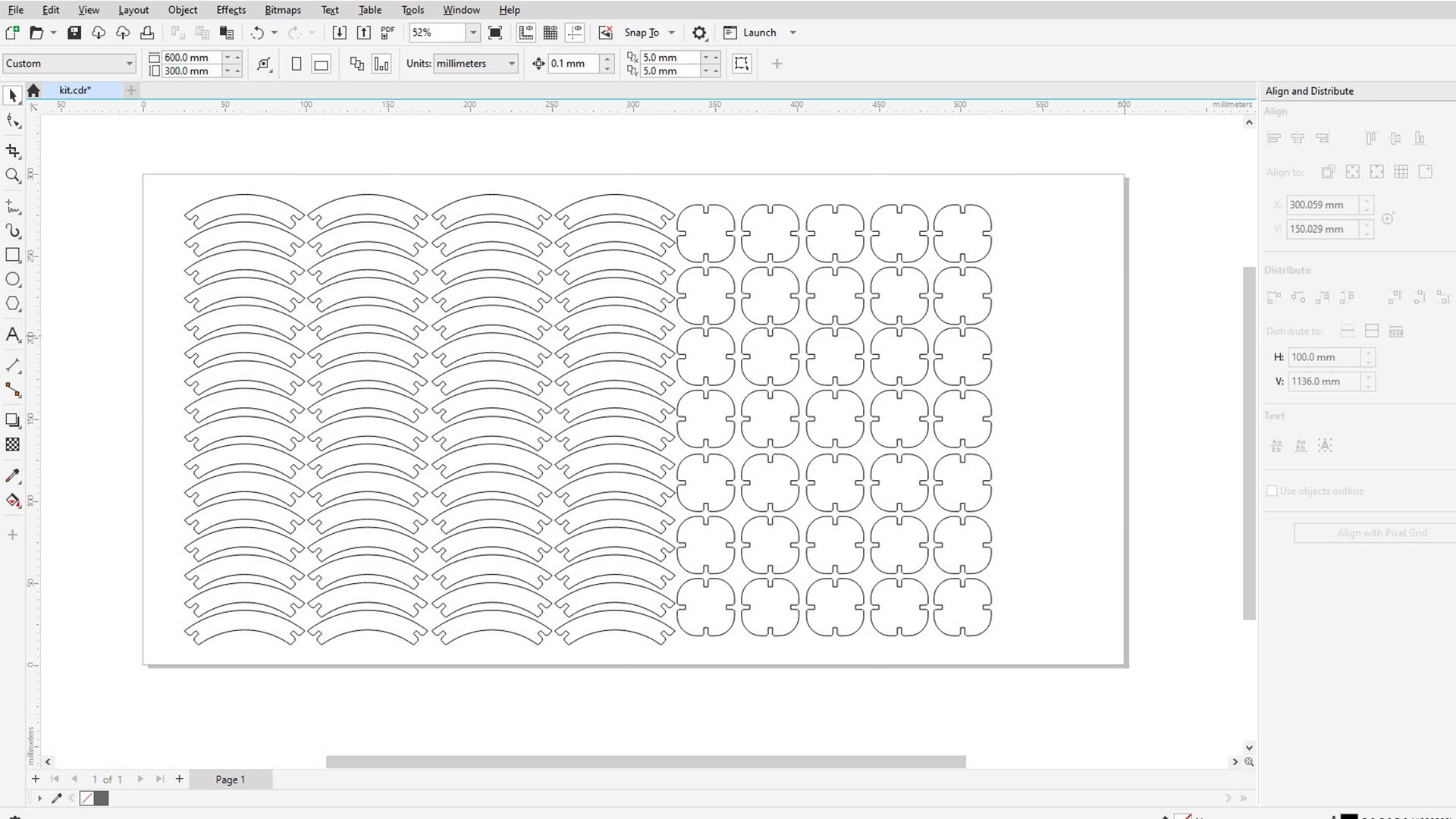
Next step is to cut pices with laser cuter. I exported them as dxf file. You can find this file here or at the bottom of this page.
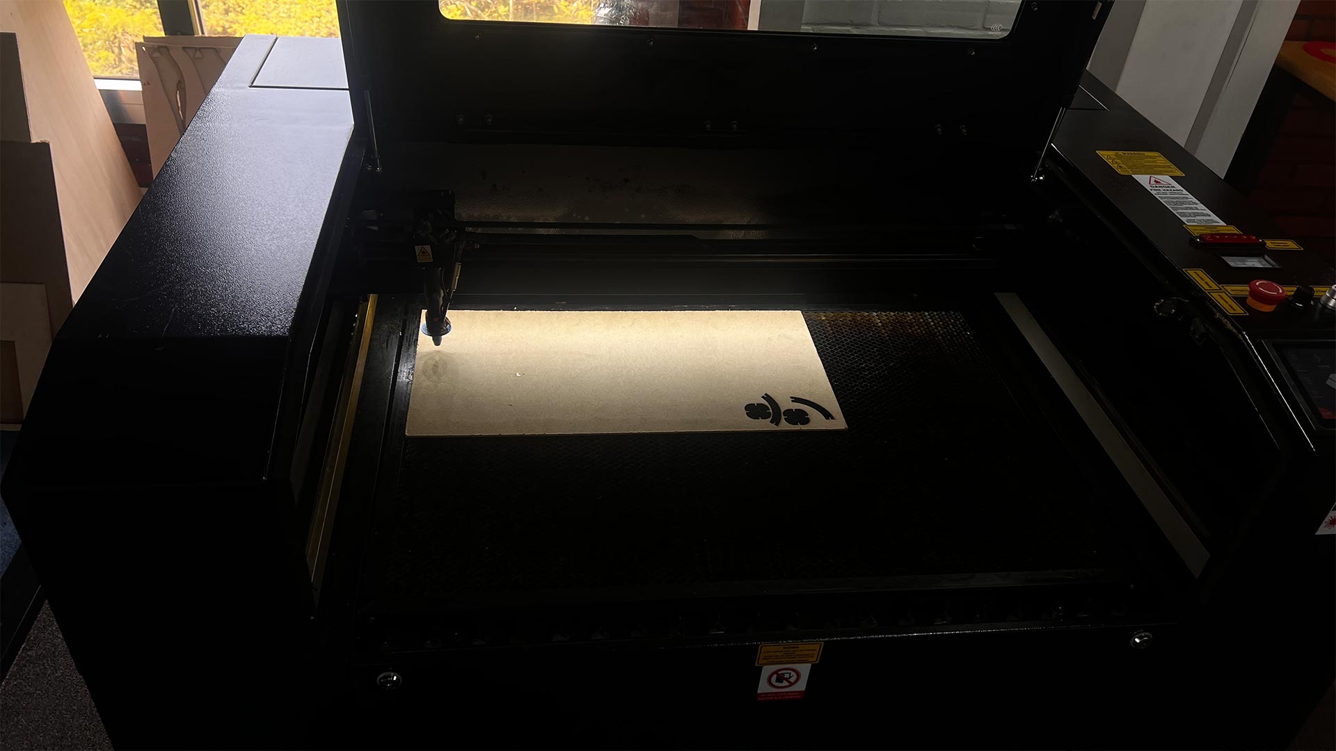
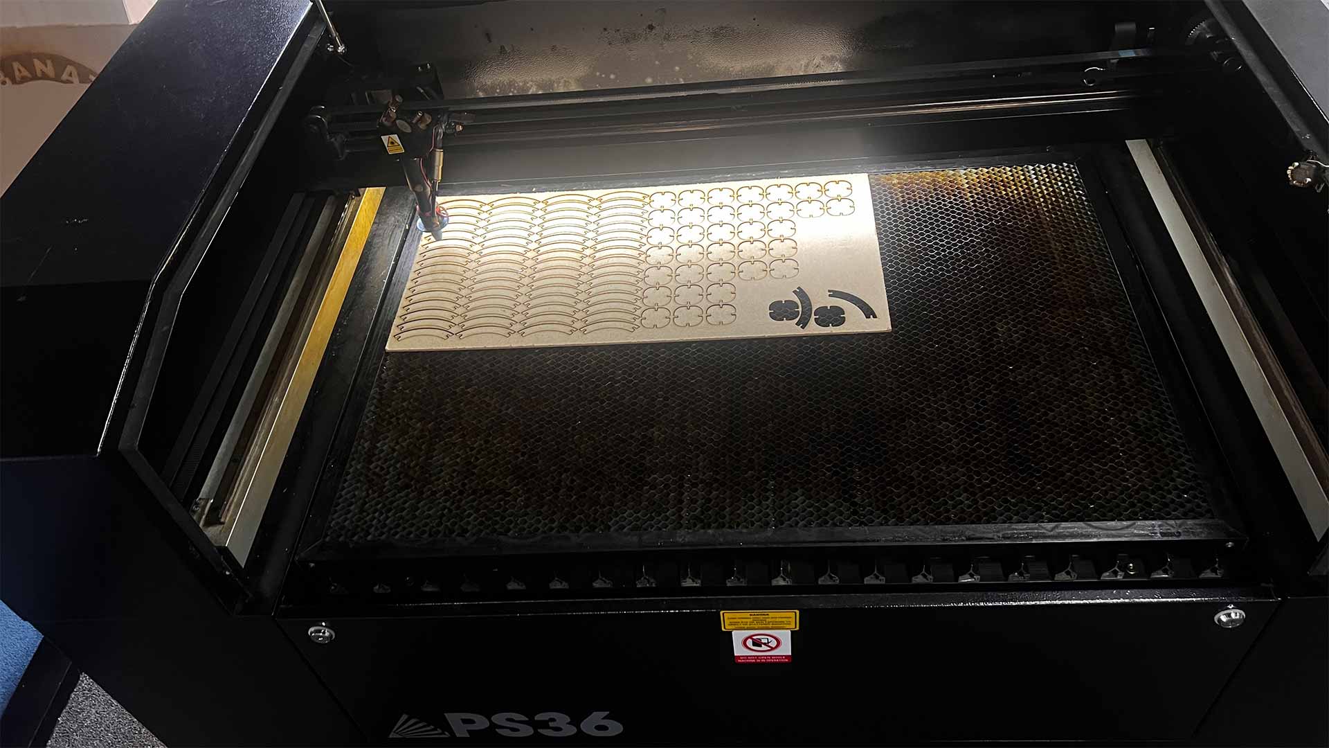
I first cut few pieces to make sure cutting parameters are set correctly.
And I placed the material into machine.
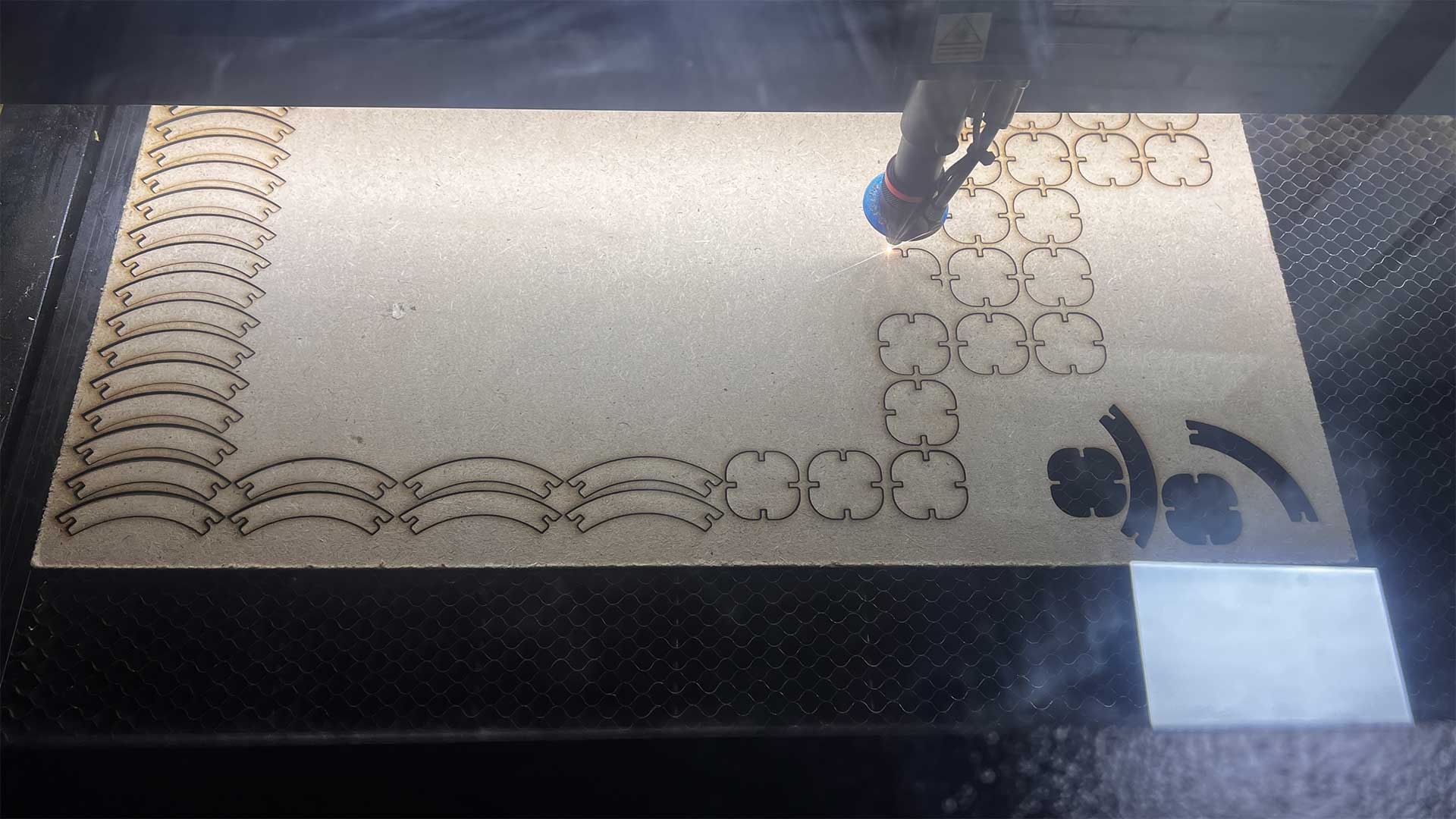
Cutting continued afterward
Cutting almost done!
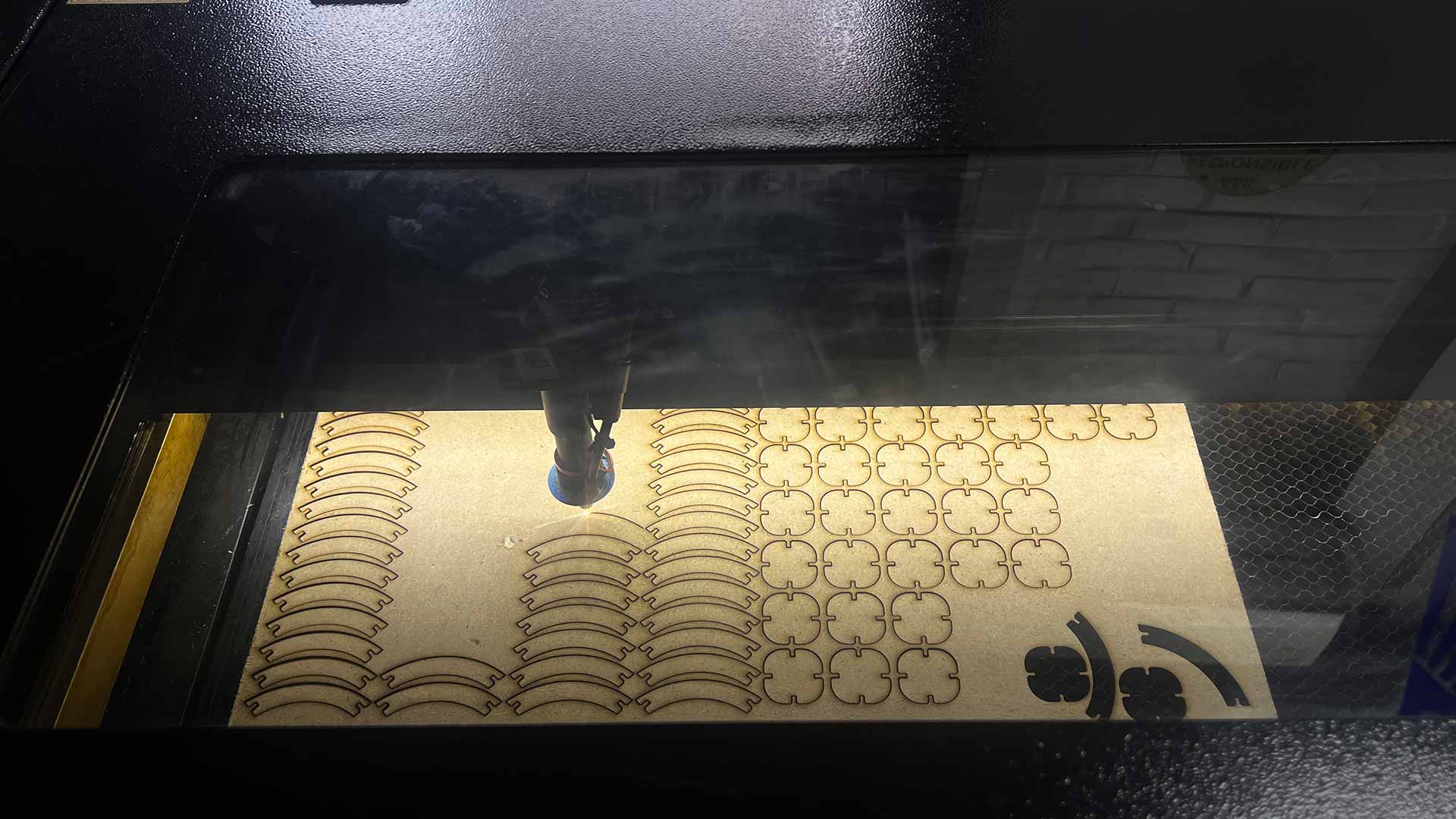
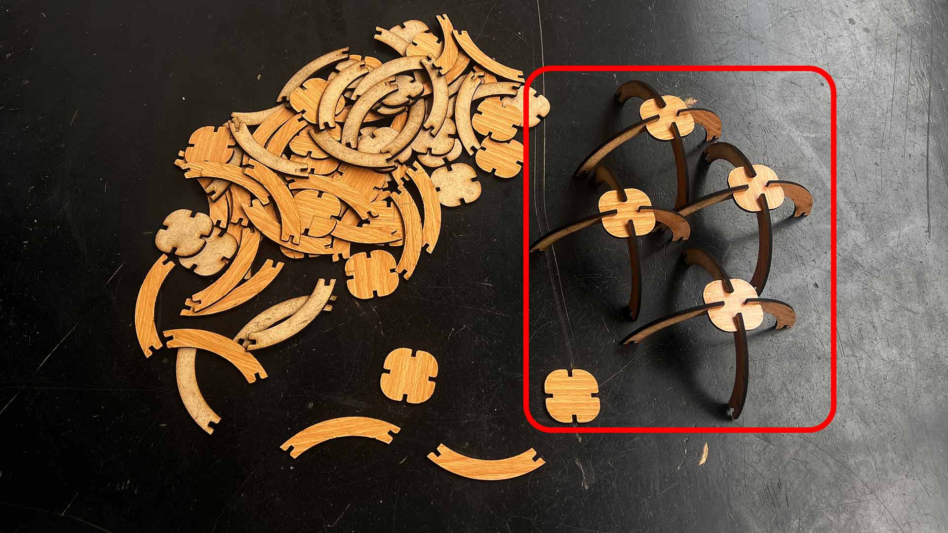
All pieces are now cut. Next process is to assemble pieces together.
Assembling
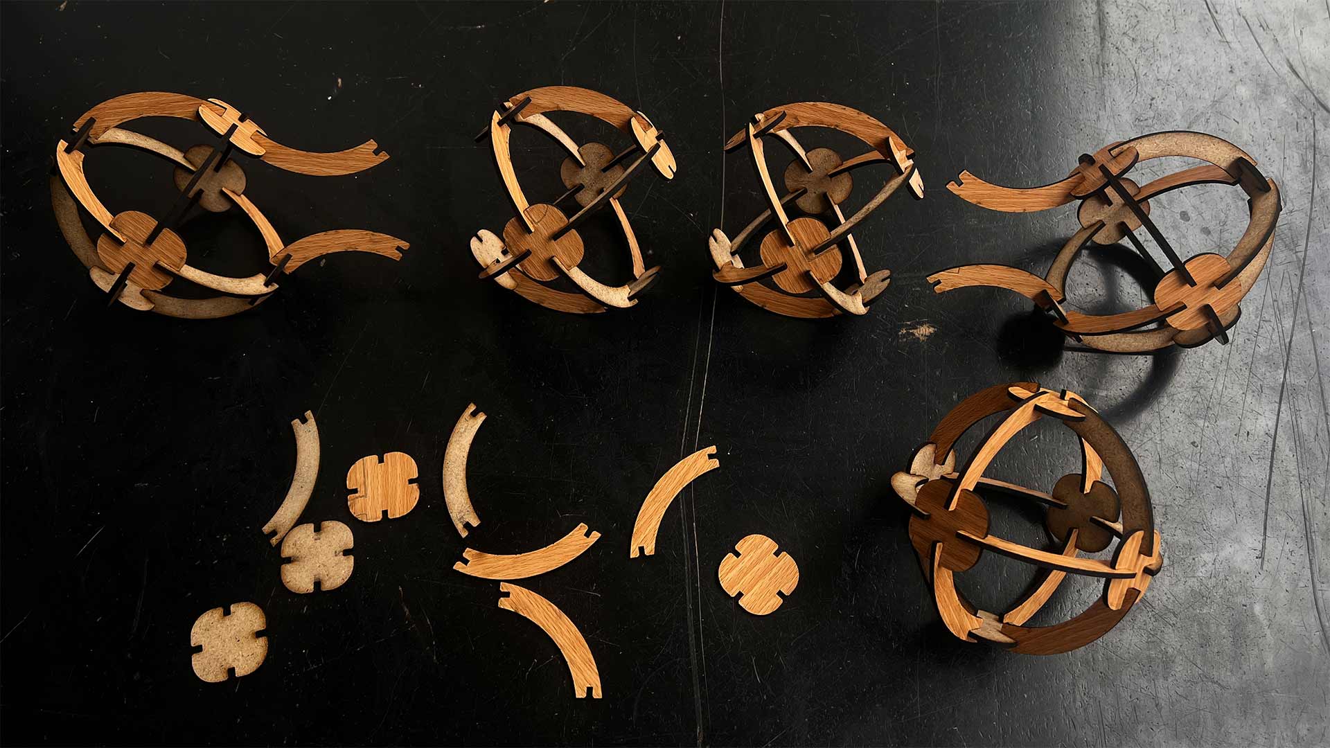
I started by assebling half spheres.
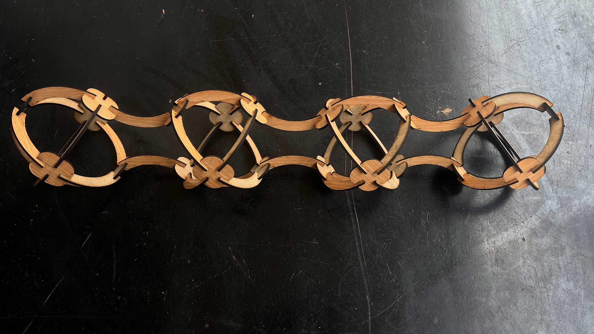
After, I assembled connectors to make full kit/shepricl shape
4 spheres connected.
Vinyl Cutter
Vinyl cutting is the process of using a computer-controlled machine (in this case vinyl cutter) to cut designs or shapes from thin sheets of vinyl or other materials like sticker paper, or stencils. The vinyl cutter uses a very small, razor-sharp blade to precisely cut along vector-based design files created in vector based computer programs like CorelDRAW or Adobe Illustrator
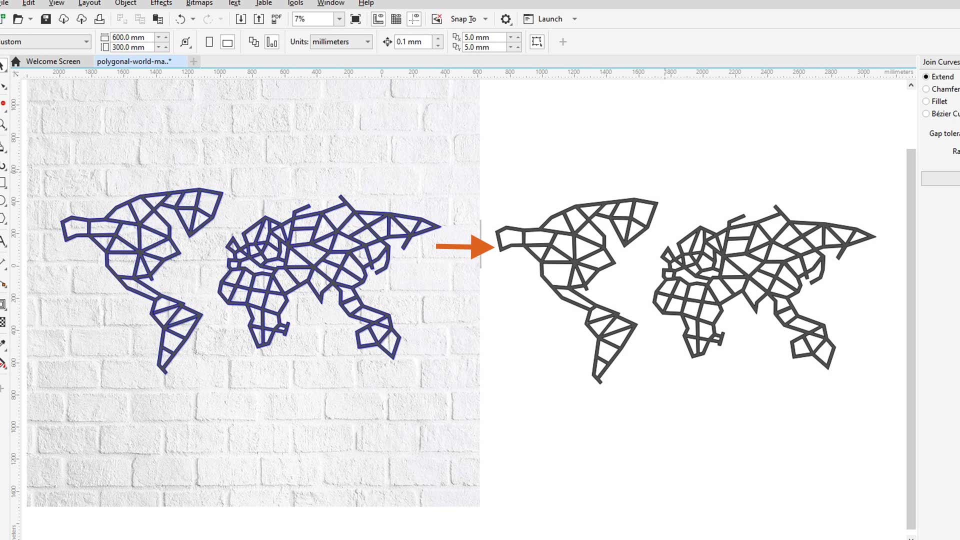
I started by creating a vector from picture. I wanted to created polygonal map (world map) to decorate my pc and cut it with vinyl machine. I used polyline tool to trace all lines of the map.
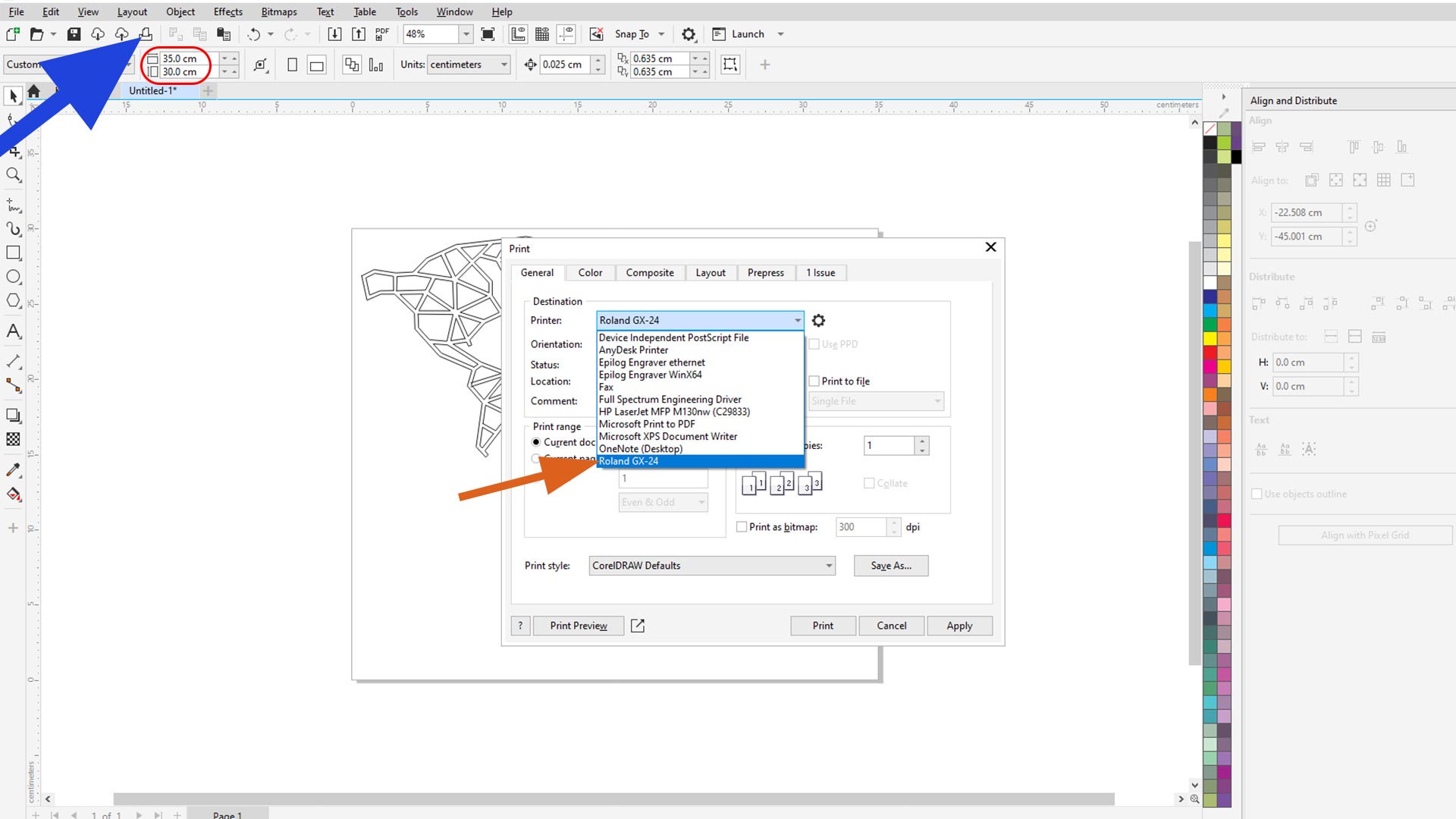
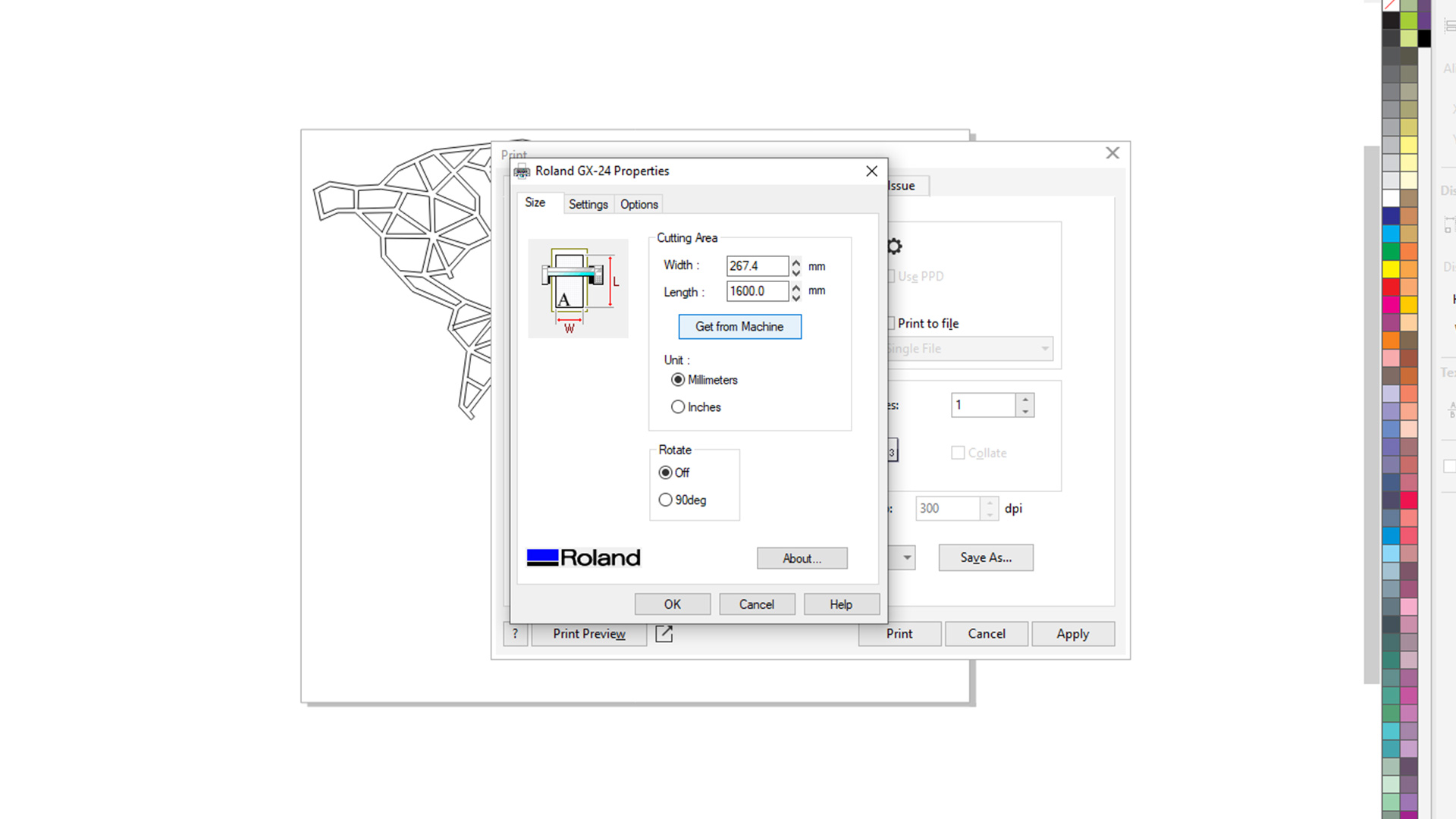
In oder to cut (cotnrol viny cutter) directly with my computer, I installed Roland plug-in. The plug-in depends up on the machine you are using.
I resized my design afterward. and connected my pc to Vinyl cutter.
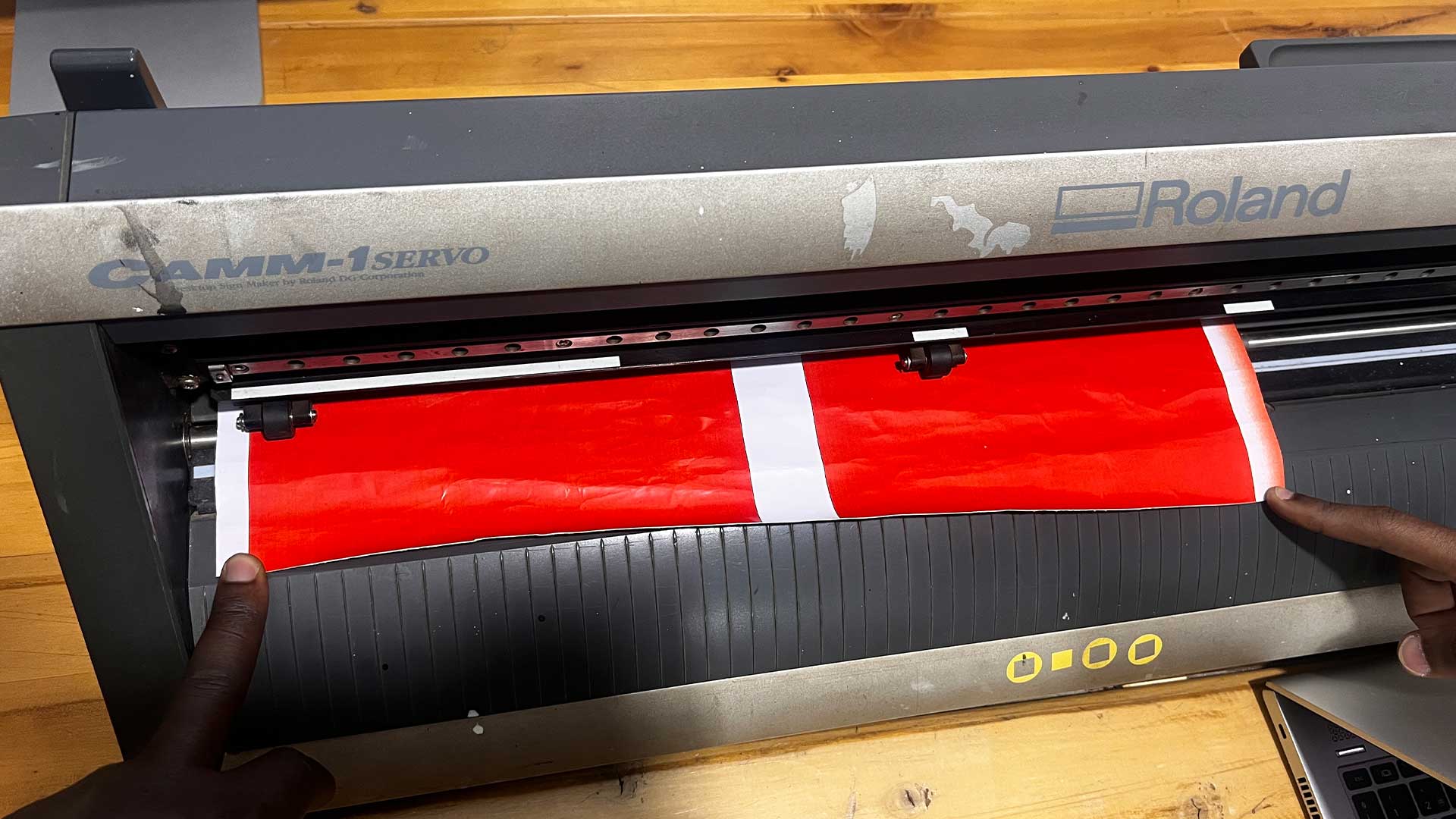
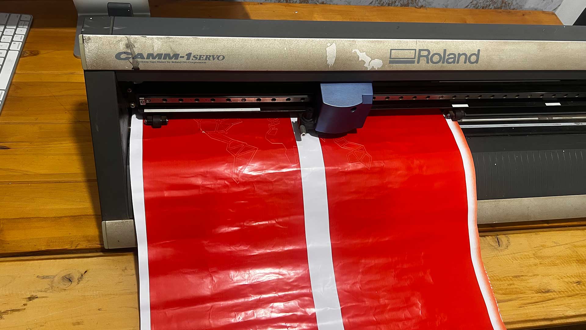
Next step is to load vinyl paper into machine. Make sure the paper is not tangled.
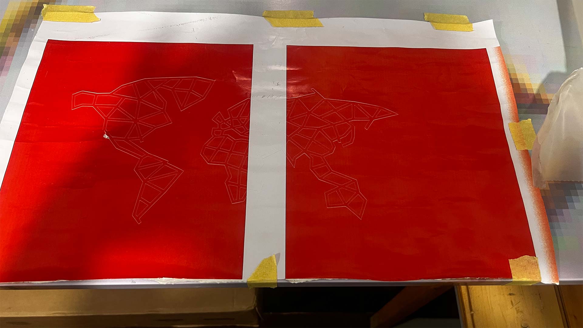
I sent the job afterward.
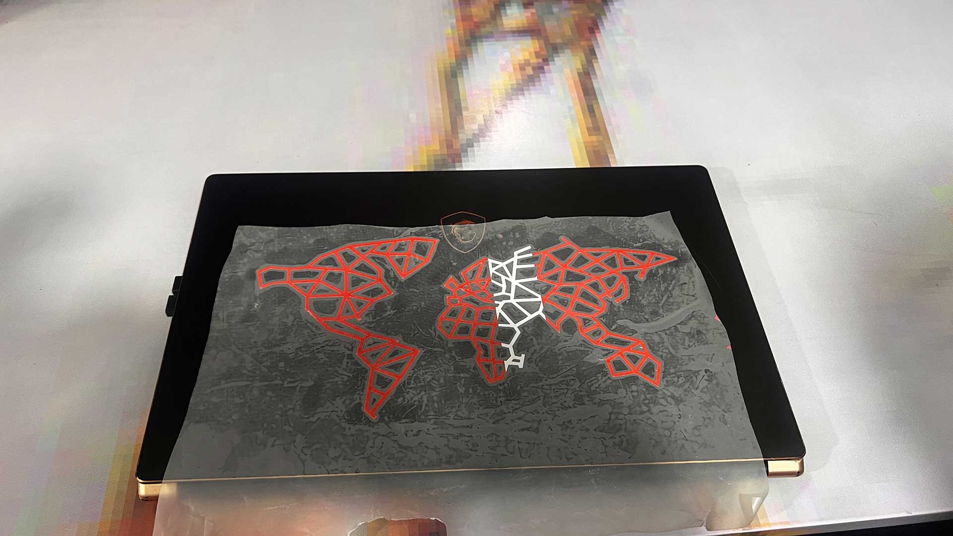
After cutting is complete, I placed the design on the table with table so that I can add transfer paper.
I added tranfer paper
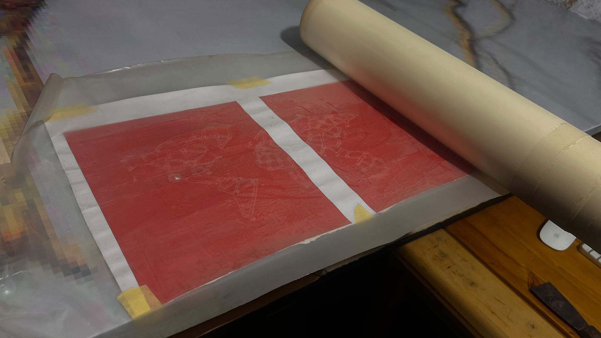
After adding tranfer paper, I removed the negavite (everyting except needed design)
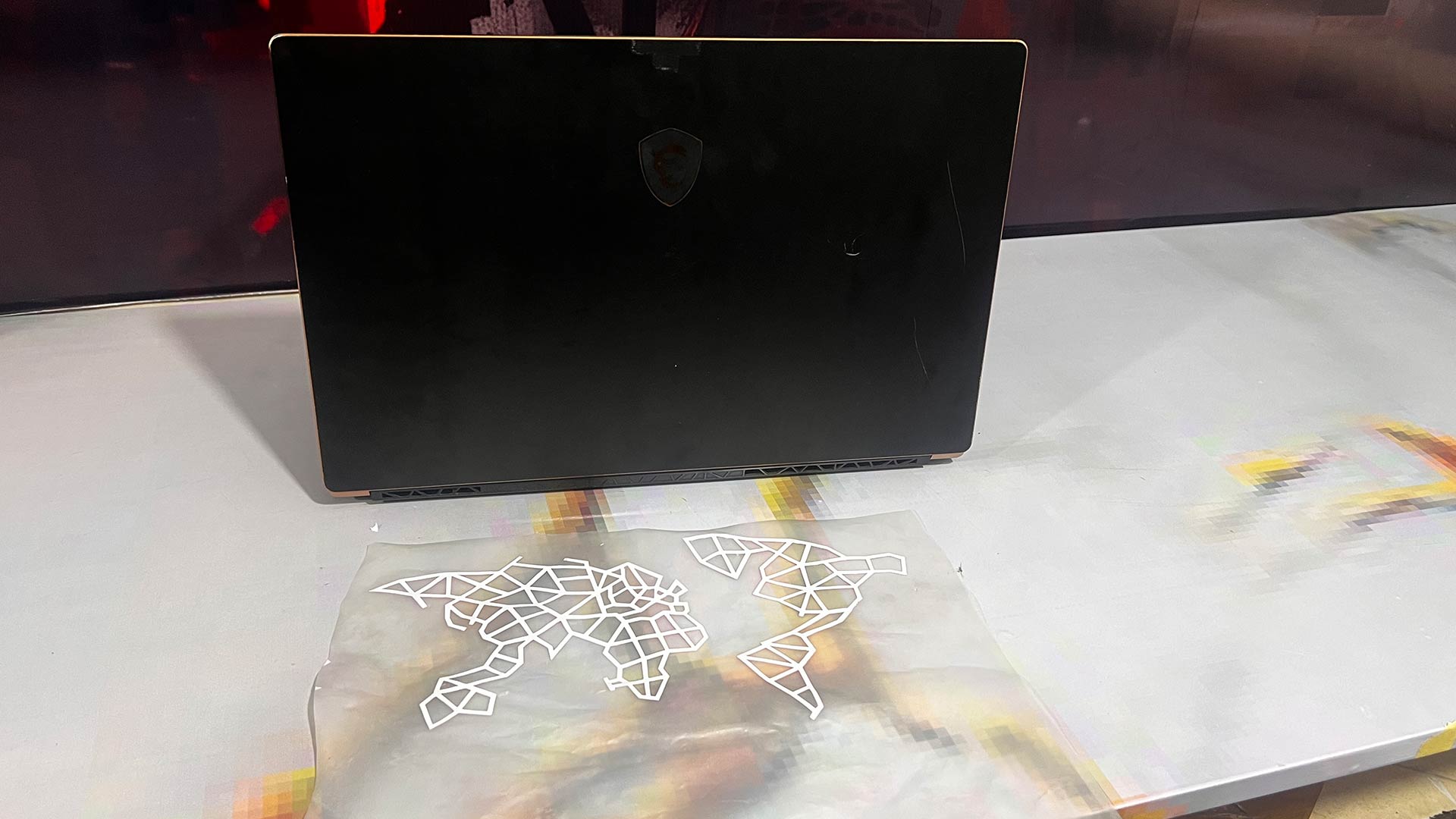
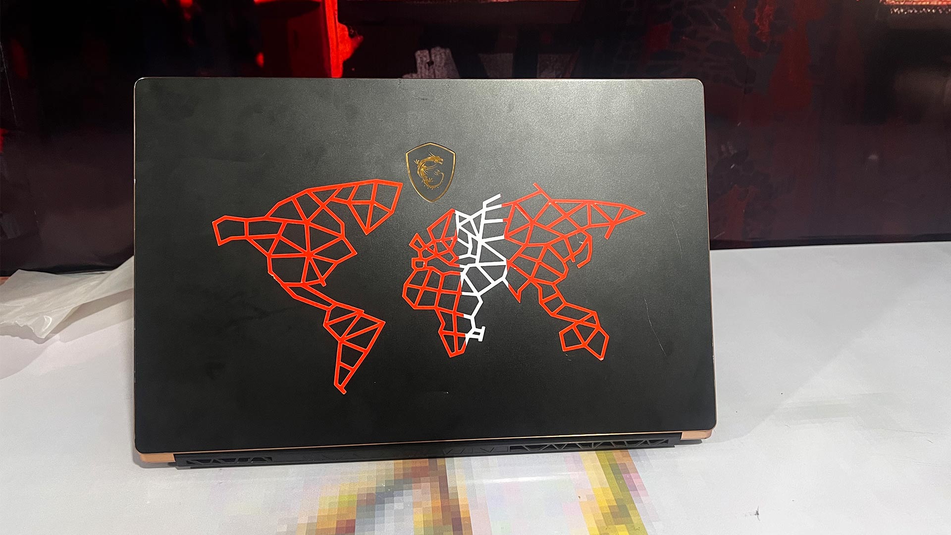
I sticked the tranfer paper on the back of computer
Final product
Download files
Here you will find the original files I designed and printed.
3D files for kit