Assignment Overview
Individual assignment:
Design and document the system integration for your final project
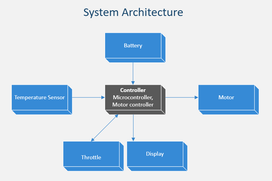
This assignment covers System Architecture that outlines all major subsystems and how they interact in an electric bike
System overview
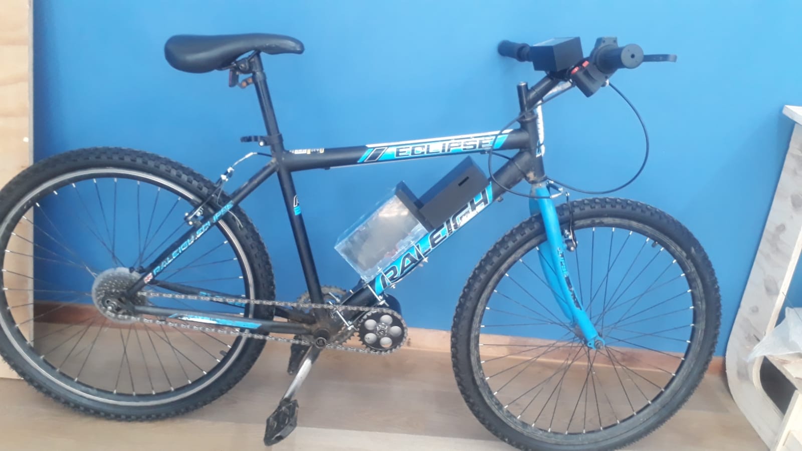
The E-Bike project integrates power electronics, mechanical systems, embedded control, and user interfacing to build a functional electric bicycle. The architecture consists of key systems: Power Supply, Motor Drive, Motor Control, User Interface, Safety Monitoring, and Mechanical Mounting.
Sub-systems
1. Power Supply System
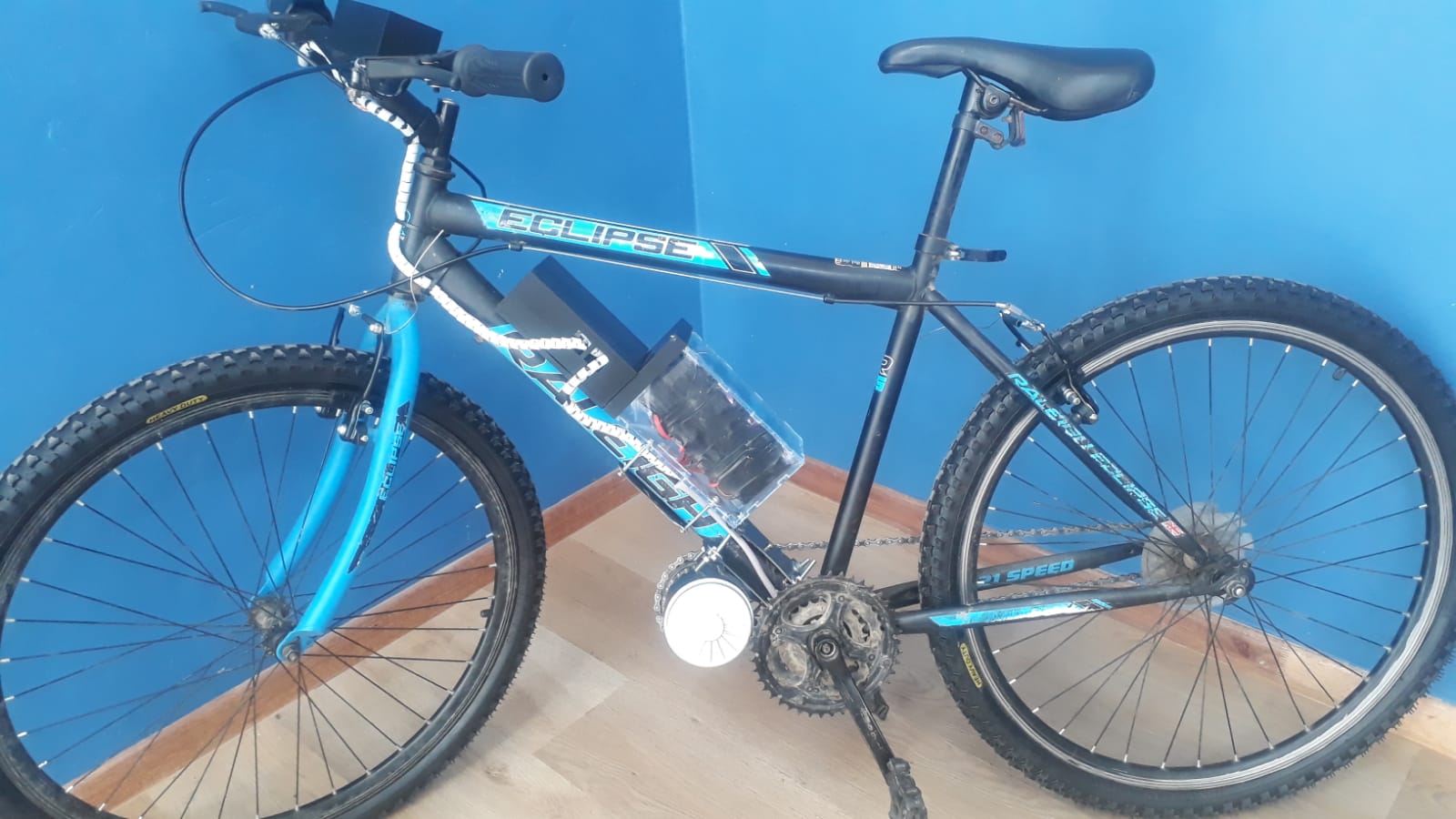
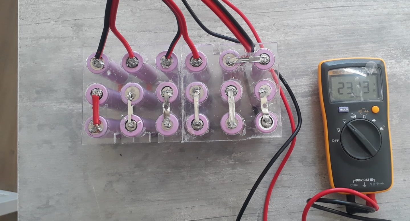
- Battery Pack (24V Li-ion): Provides the primary power source. Composed of multiple 3.7V cells connected in series and parallel to reach the desired voltage and current capacity. Custom-designed bracket that securely attaches the battery to the bicycle frame, preventing movement during rides.
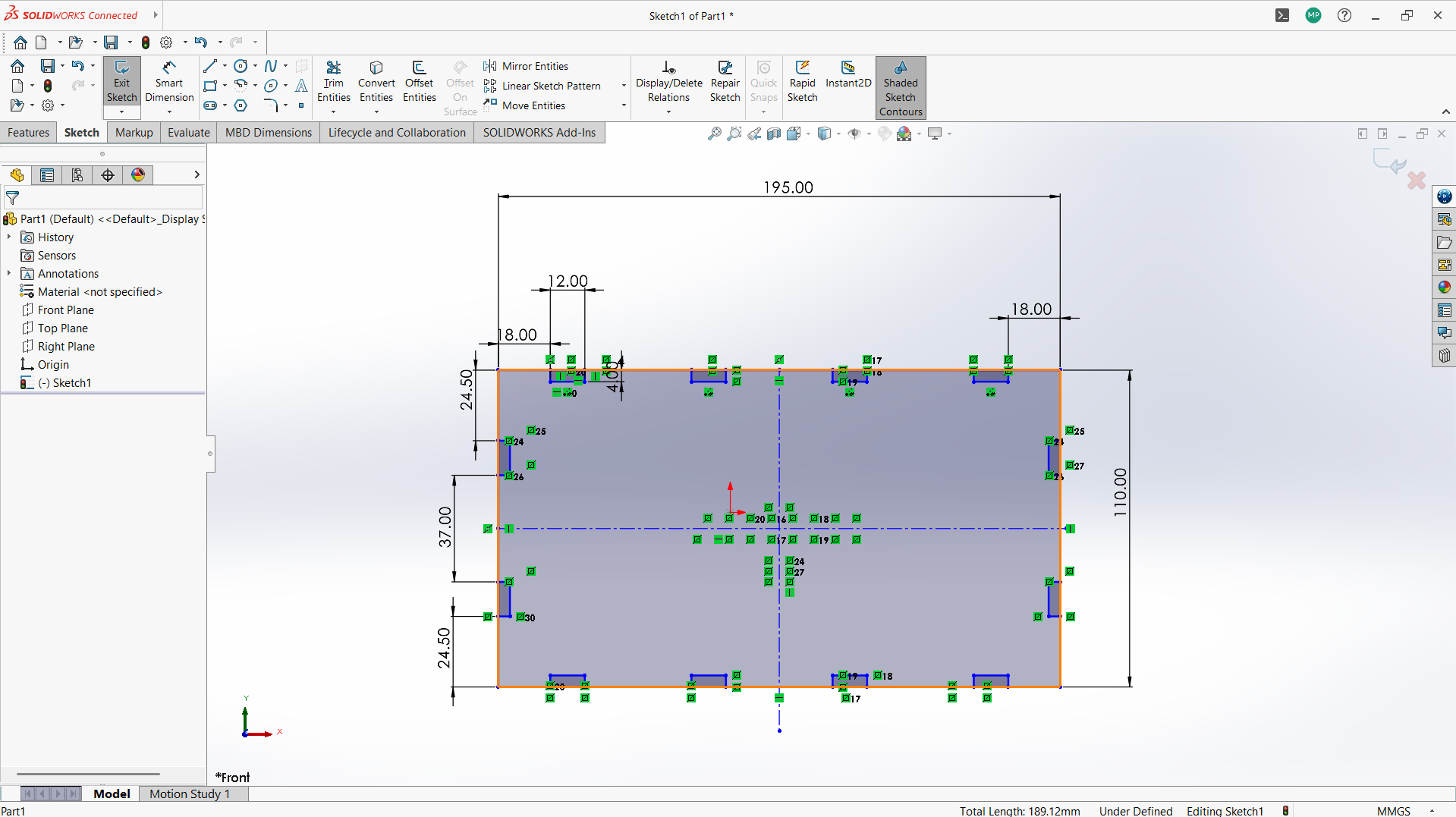
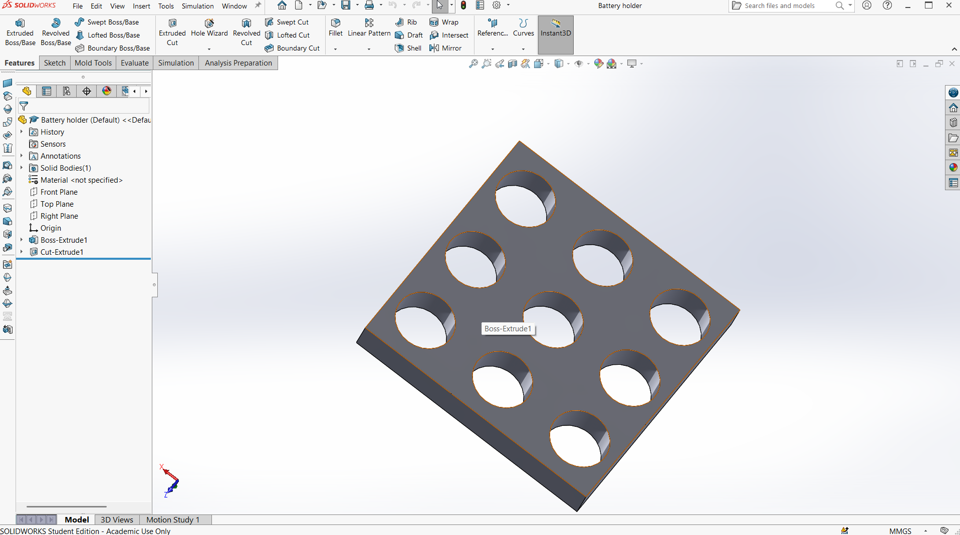
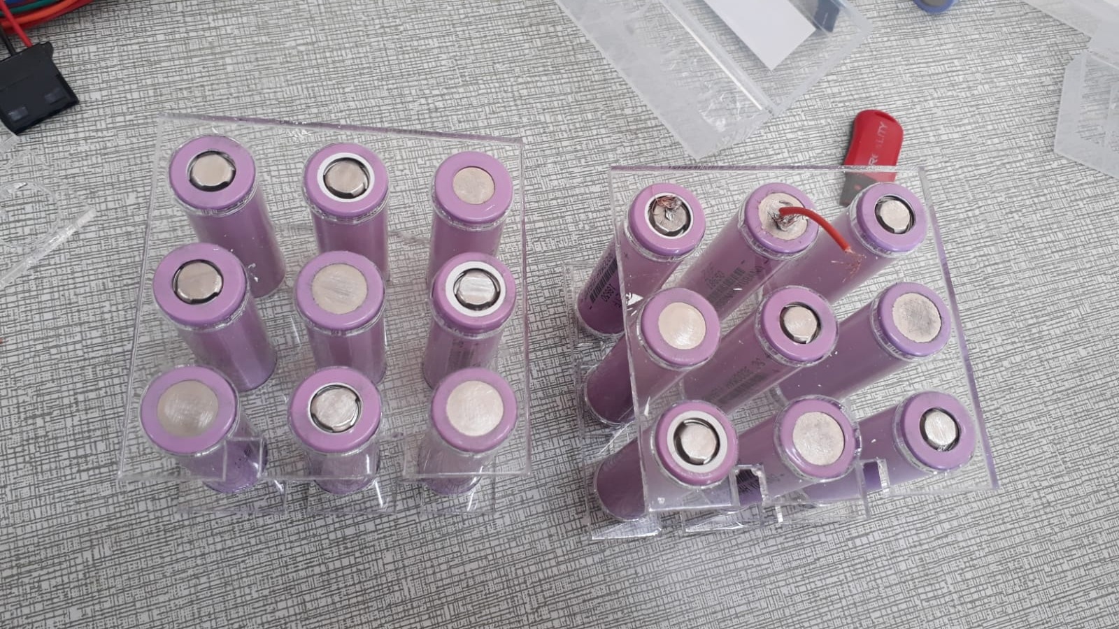
- Battery Cells Holder: Plastic grid layout for organizing the cylindrical cells, ensuring easy wiring and structural integrity.
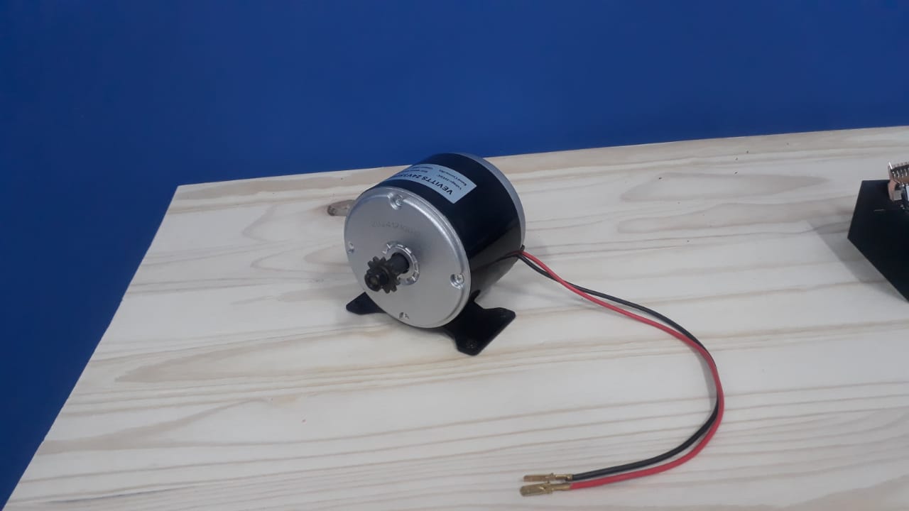
- Hub Motor: A DC hub motor mounted in a way to drive the rear wheel with a drive chain. It provides direct drive without transmission systems, enabling efficient power transfer and reduced maintenance.
- Temperature Sensors: Installed on controller to monitor MOSFET overheating. Automatically shuts off or limits power if temperature exceeds safety thresholds.
- Voltage Sensors: Continuously measure battery voltage to prevent deep discharge and ensure optimal performance.
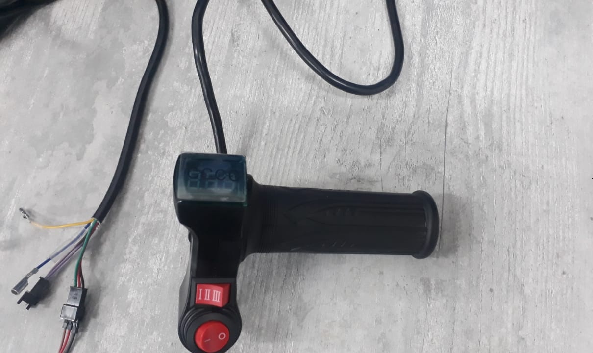
- Throttle: Analog 0–5V signal or Hall-effect sensor. User controls acceleration by twisting the handlebar throttle.
- LCD Display: Real-time display of speed, battery level, temperature, and power status. Also includes odometer functionality.
- Motor Controller: Custom PCB for DC motor control. Receives throttle and drives the motor accordingly.
- Outputs: High-current PWM signals for motor drive, safety interrupt signals.
- DC-DC Converter: Steps down the 24V battery voltage to 5V for microcontroller and display operation.
- Features: Soft start to avoid jerks, smooth braking, current limiting to protect motor and battery.
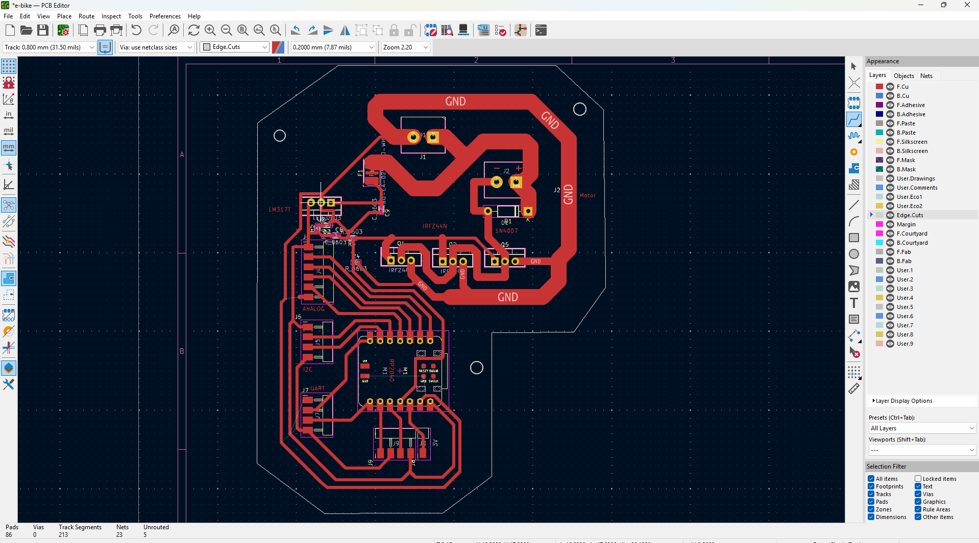
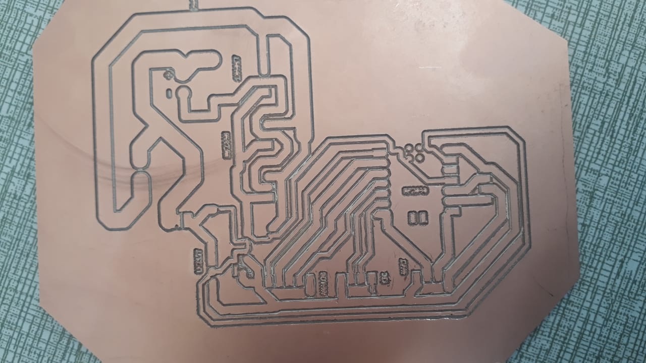
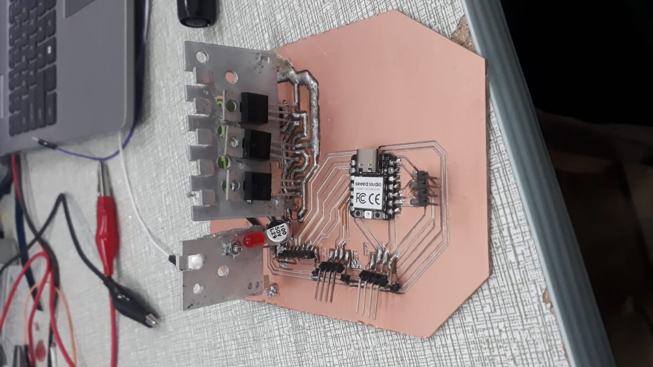
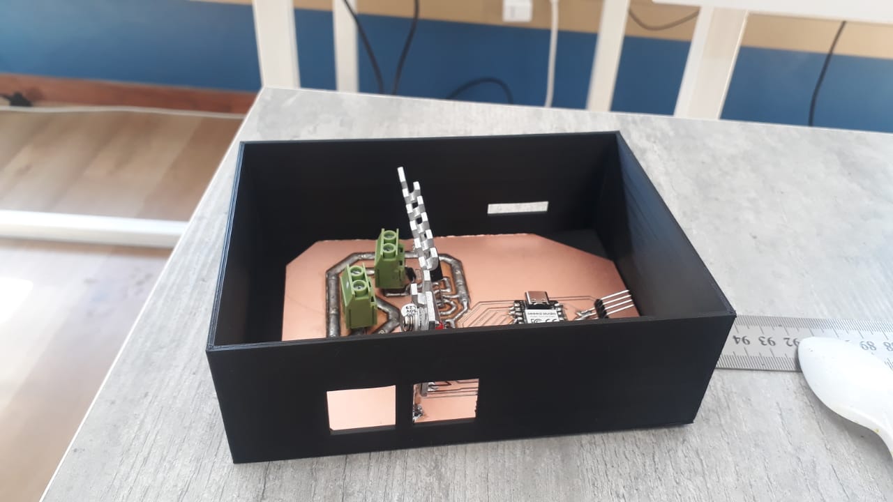
- Motor Driver PCB: Combines a microcontroller (e.g. Seeed Xiao RP2040) and IRFZ44 driver circuitry. Interfaces with sensors and display modules.
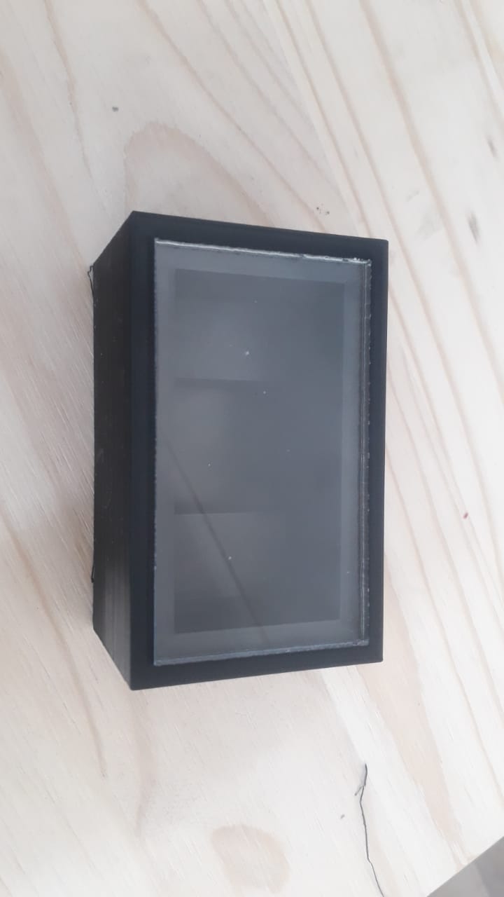
- Battery Enclosure: Waterproof case to house the battery pack. Mounted on the down tube.
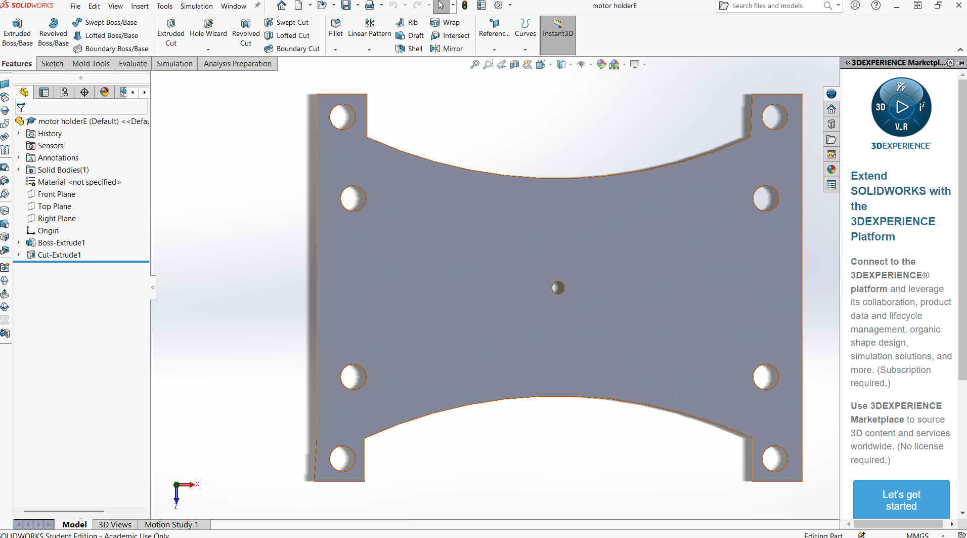
- Motor Mount: Reinforced dropouts and torque arms to hold the motor securely.
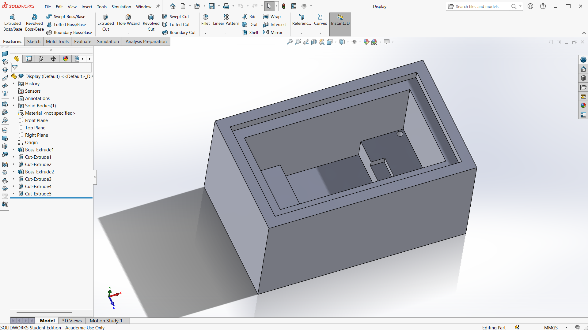
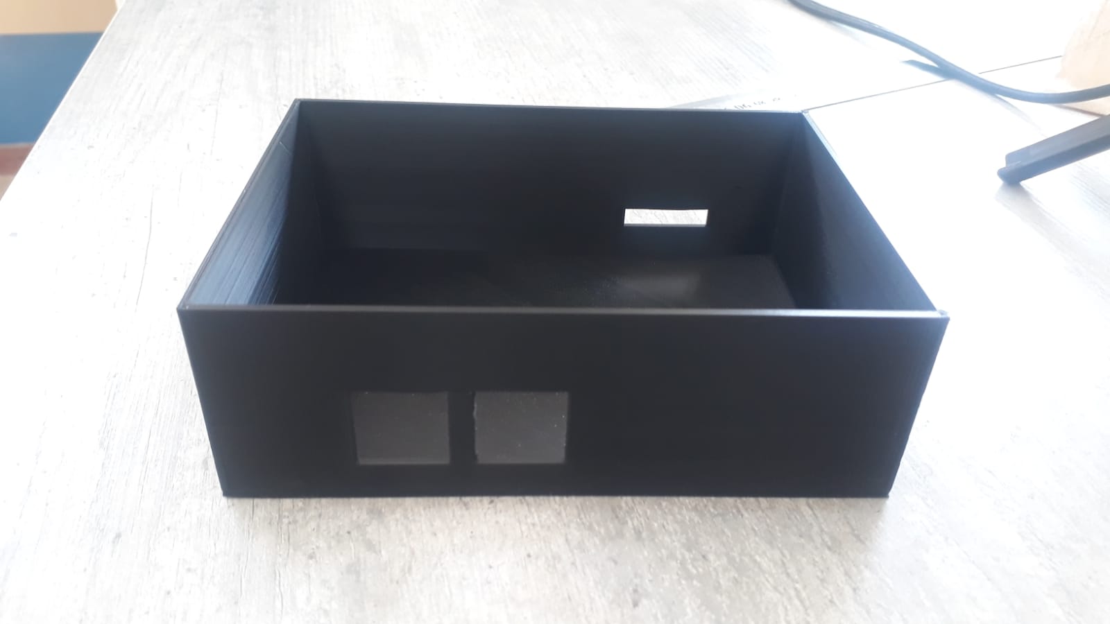
- Controller Mount: 3D-printed mounted to the frame. Ensures airflow and easy access.
- Wiring Management: Sleeving, zip ties, and routing channels to keep wires organized and safe from wear.
- Torque Arms: Prevent motor axle from rotating under torque. Essential for high-power hub motors.
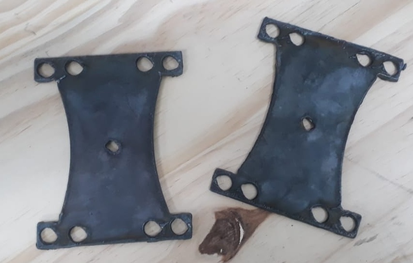
- Fasteners: Anti-vibration stainless steel bolts for mounting all components securely.
- Waterproofing: Rubber gaskets, silicone sealant, and conformal coating to protect electronics from moisture.
- All subsystem connected and assembled.