Interface and Application Programming
Group assignment:
Compare as many tool options as possible.
Document your work on the group work page and reflect on your individual page what you learned.
Group assignment link Group
Individual assignment:
Write an application for the embedded board that you made, that interfaces a user with an input and/or output device(s)
This assignment covers both output and input device communication with the interface. The devices are connected to micro-controller through breadboard as a switch.
Tha application send commands to the output devices and read data from input devices and display it on the interface.
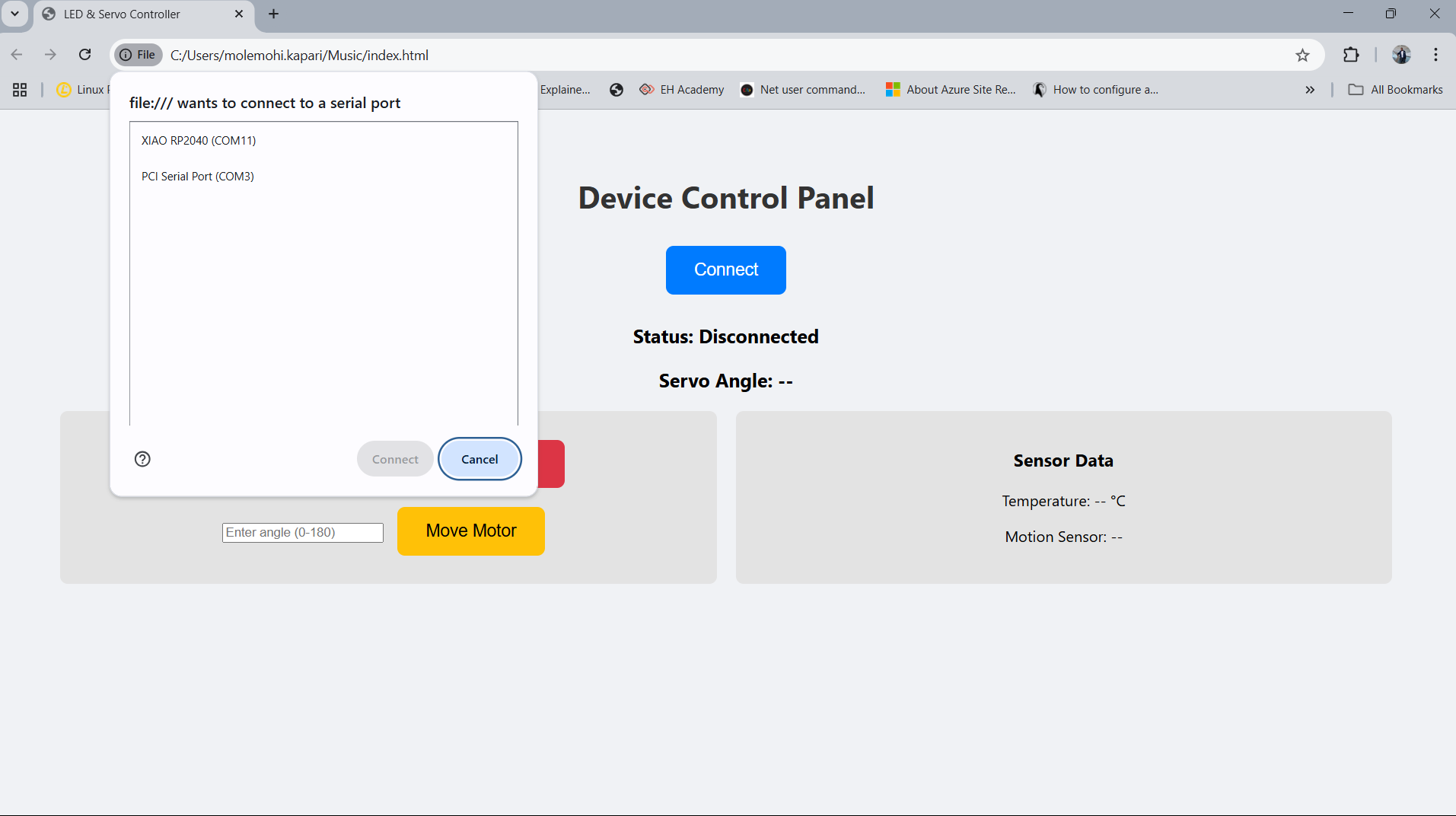
It firstly connect to the micro-controller using usb serial through web serial port.
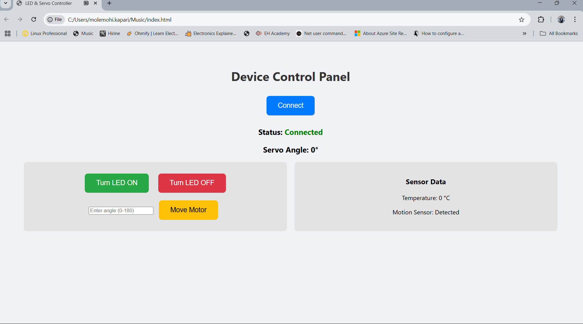
- Turns LED ON and OFF through the buttons
- Turns the servo motor in the specified angle entered on the interface text box
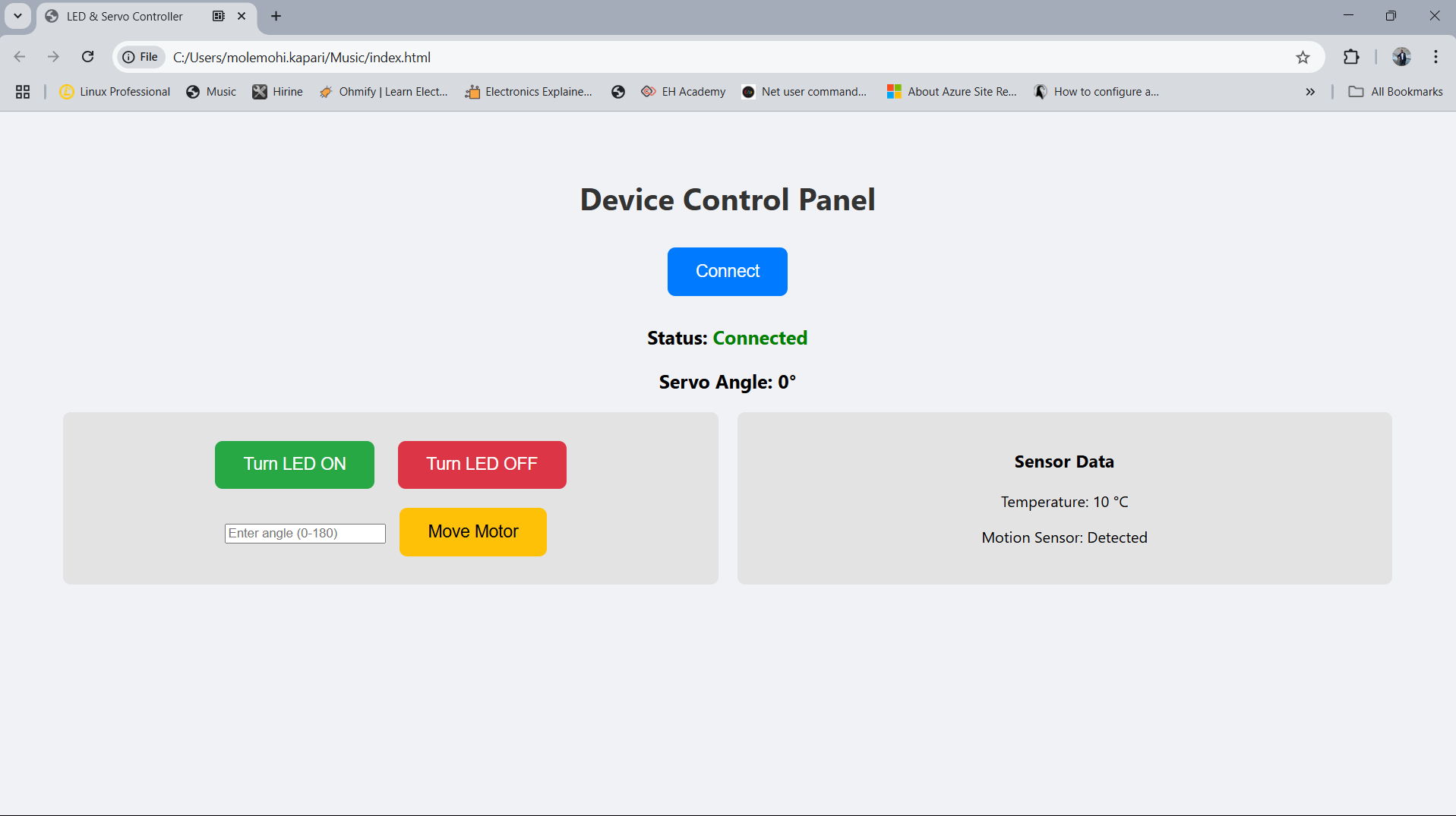
- Read temperature sensor and display the reading on the interface
- Read PIR motion sensor data and display on the interface
/*********
          Arduino IDE script
          *********/
          #include   // Library for I2C LCD (not used in this sketch but can be added for display functionality)
            #include               // Include Servo library to control servo motor

            // === Pin Definitions ===
            const int ledPin = A3;          // LED connected to analog pin A3 (used as digital output)
            const int pirPin = A1;          // PIR motion sensor connected to analog pin A1 (used as digital input)
            const int tempPin = A2;         // LM35 temperature sensor connected to analog pin A2
            const int servoPin = D9;        // Servo motor control pin (PWM capable)

            Servo myServo;                  // Create a Servo object
            int currentAngle = 0;           // Variable to track current servo angle

            void setup() {
              Serial.begin(9600);           // Initialize serial communication at 9600 baud rate

              pinMode(ledPin, OUTPUT);      // Set LED pin as output
              pinMode(pirPin, INPUT);       // Set PIR sensor pin as input

              myServo.attach(servoPin);     // Attach servo to the defined pin
              myServo.write(currentAngle);  // Initialize servo position to 0 degrees
            }

            void loop() {
              // === Read Motion Sensor ===
              int pirValue = digitalRead(pirPin);  // Read motion status (HIGH = motion detected, LOW = no motion)

              // === Read Temperature Sensor (LM35) ===
              // Convert analog reading to voltage, assuming 0.5V reference (adjust if using 5V ref)
              float voltage = analogRead(tempPin) * (0.5 / 1023.0);
              // Convert voltage to temperature in °C (adjusted by factor of 4 for calibration/simulation)
              float temperature = voltage * 10.0 * 4;

              // === Send Sensor Data Over Serial in JSON Format ===
              Serial.print("{\"angle\":");
              Serial.print(currentAngle);                // Include current servo angle
              Serial.print(",\"temperature\":");
              Serial.print(temperature, 1);              // Print temperature with 1 decimal place
              Serial.print(",\"motion\":\"");
              Serial.print(pirValue == HIGH ? "Detected" : "None");  // Include motion status as string
              Serial.println("\"}");

              // === Check for Incoming Serial Commands ===
              if (Serial.available()) {
                String command = Serial.readStringUntil('\n');  // Read the incoming command until newline
                command.trim();                                 // Remove leading/trailing spaces

                // Command "1" turns the LED ON
                if (command == "1") {
                  digitalWrite(ledPin, HIGH);
                }
                // Command "0" turns the LED OFF
                else if (command == "0") {
                  digitalWrite(ledPin, LOW);
                }
                // Command starting with "m" sets the servo angle, e.g., "m90" sets it to 90 degrees
                else if (command.startsWith("m")) {
                  int angle = command.substring(1).toInt();     // Extract angle from command
                  angle = constrain(angle, 0, 180);             // Constrain angle to valid range
                  myServo.write(angle);                         // Move servo to specified angle
                  currentAngle = angle;                         // Update current angle variable
                }
              }

              delay(1000);  // Wait 1 second before repeating loop (controls update rate)
            }
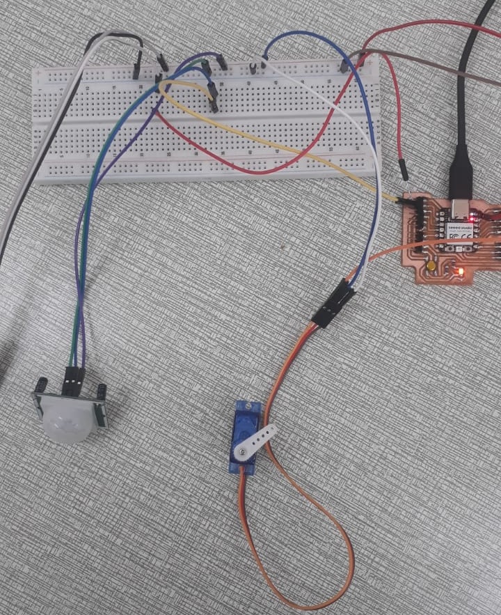
- Before and After Connection
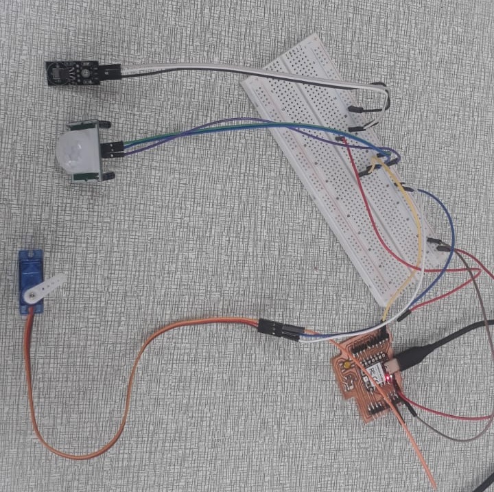
The images below show the physical state of the project after all components were properly connected. Initially, only the micro-controller was set up without external components. After connecting the PIR motion sensor, temperature sensor, servo motor, and LED, the system was ready for data acquisition and interaction.

Servo Motor Angle Demonstration
The servo motor in this project is controlled via serial commands. When a command like m30 is sent, the servo
rotates to the given angle, and similarly, m180 rotates it to 180°. This behavior is verified through both the physical
servo movement and serial feedback.


Temperature Sensor Readings
The system includes an analog temperature sensor connected to pin A2. The sensor outputs 10mV/°C, so an analog-to-digital conversion is required. The following formula was used to scale the reading:
float voltage = analogRead(tempPin) * (5.0 / 1023.0); // Convert analog reading to voltage
float temperature = voltage * 100.0;                 // Convert voltage to temperature in °C
Below are screenshots showing real-time temperature readings printed in the Serial Monitor. These values are also packed into a JSON structure and sent over serial for possible integration with a web interface or desktop application.
Project Connections and Components
The setup includes the following components:
- Arduino-compatible micro-controller (Xiao RP2040)
- PIR motion sensor (for motion detection)
- Analog temperature sensor
- Servo motor (angle control via serial input)
- LED (indicator that can be turned ON/OFF remotely)
Project Demonstration Video
This video demonstrates the full functionality of the system. It shows motion being detected, temperature readings being sent over serial, servo movements based on input, and LED control via serial commands. It serves as a live verification of the implementation.
Code and Interface Files
The following files are included as part of the project:
- HTML File – A web-based interface for interacting with the Arduino via serial.
- Arduino Code File – Contains the full sketch used in this implementation.