Mechanical design
Group assignment: - Design a machine that includes mechanism+actuation+automation+application
- Build the mechanical parts and operate it manually
- Document the group project and your individual contribution
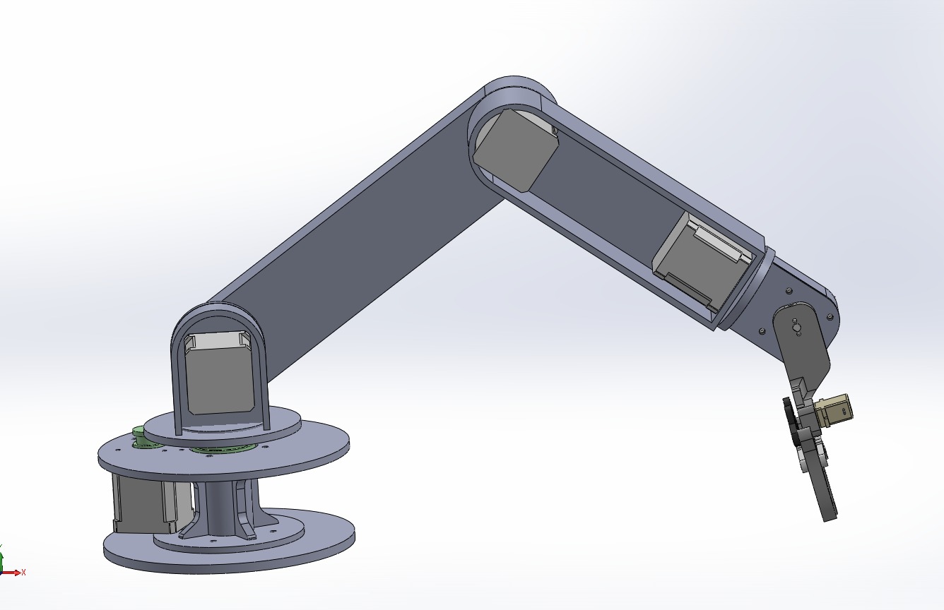
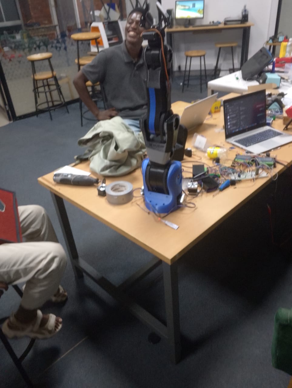
In this assignment we were working on the development of the robot arm for the group.
For machine design, we built a 5-axis robotic arm which will be controlled using web interface control panel.
Other team members handled the mechanical structure and electronics, I was in charge of writing the firmware and developing the interface to control the robot.
Group link
My Role: Assisting in Mechanical Assembling & Control Interface Designing
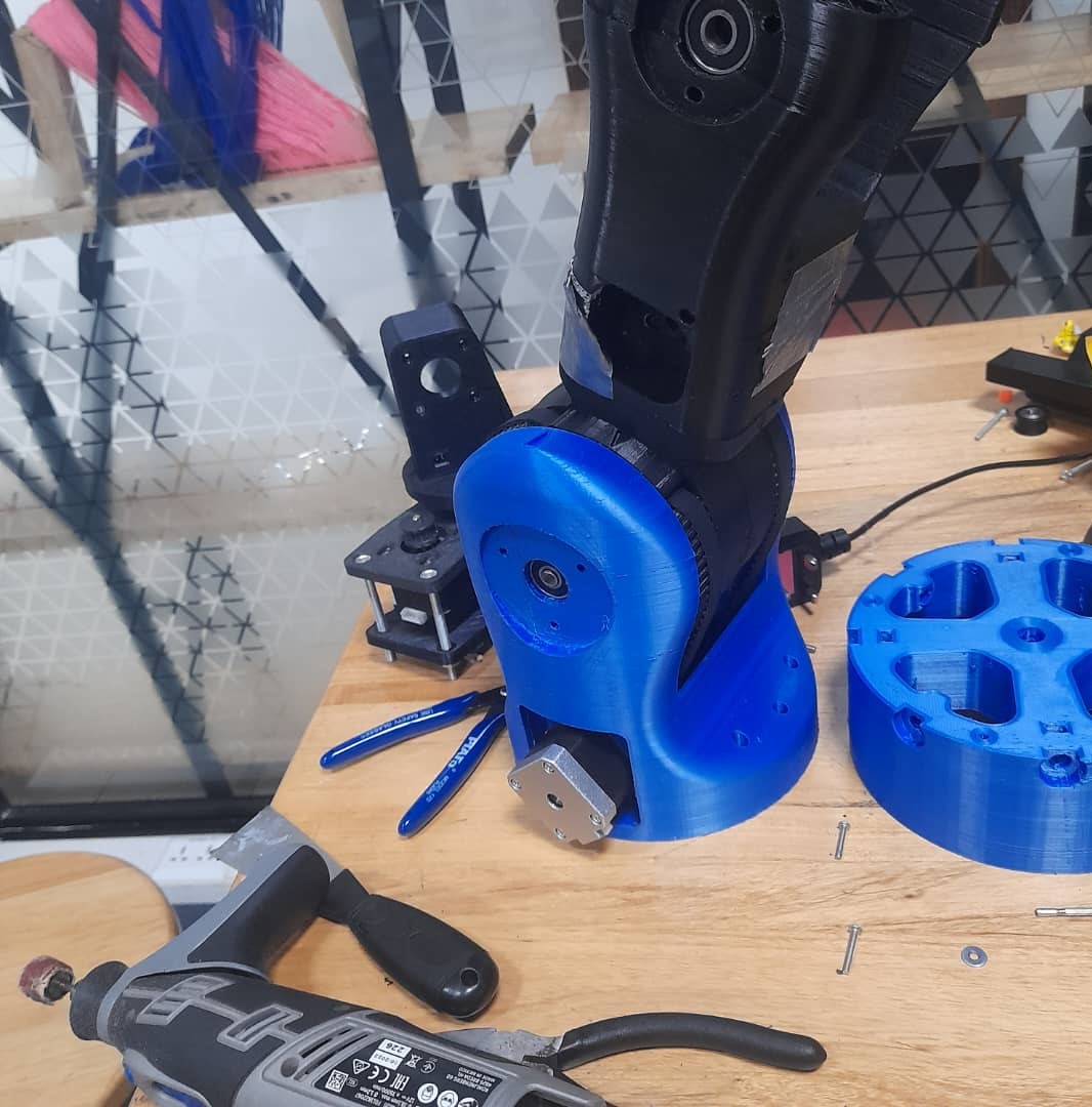
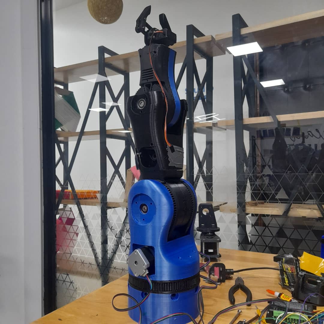
- Mechanical Assembly:
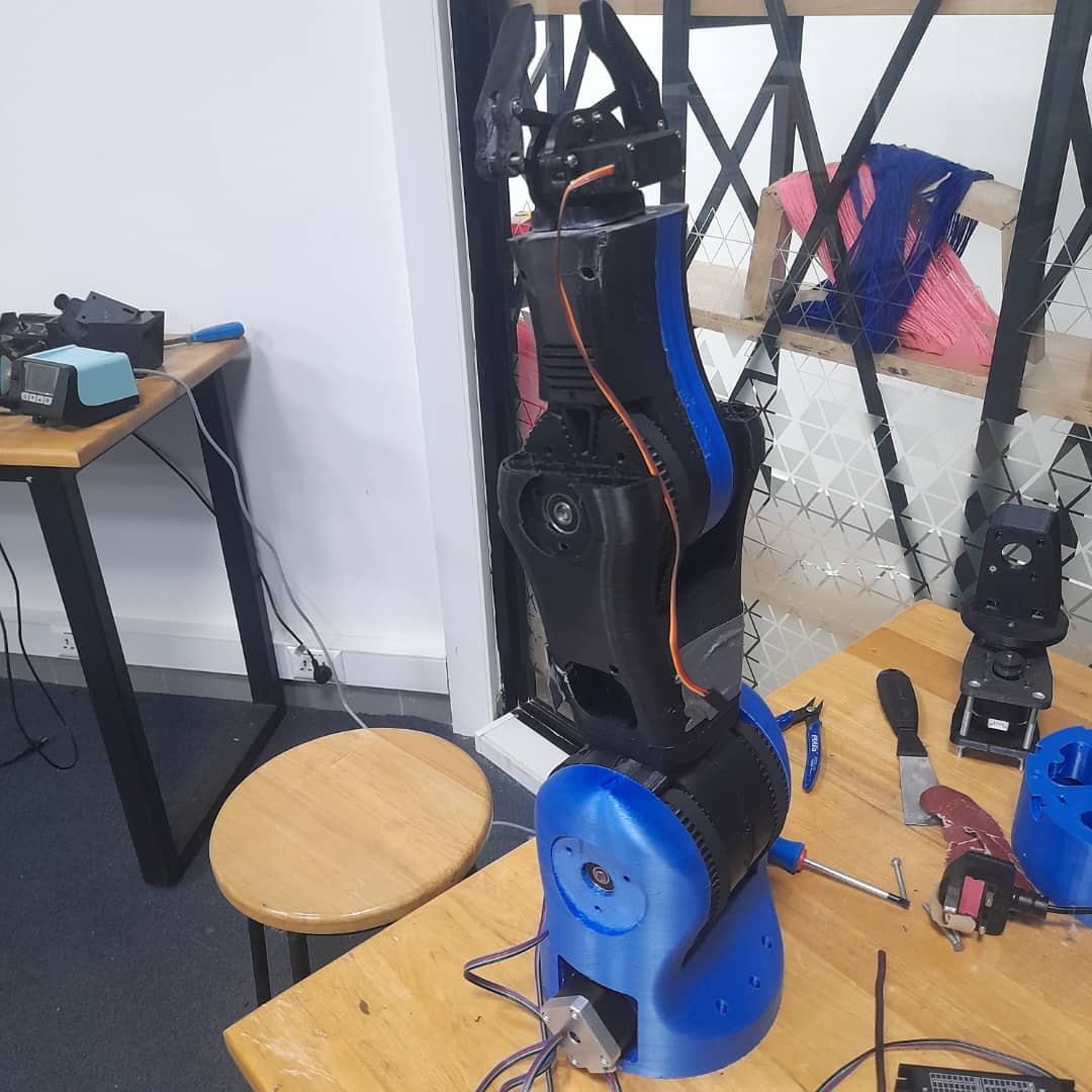
- Assisted in assembling robotic arm joints: base, shoulder, elbow, wrist, and gripper.
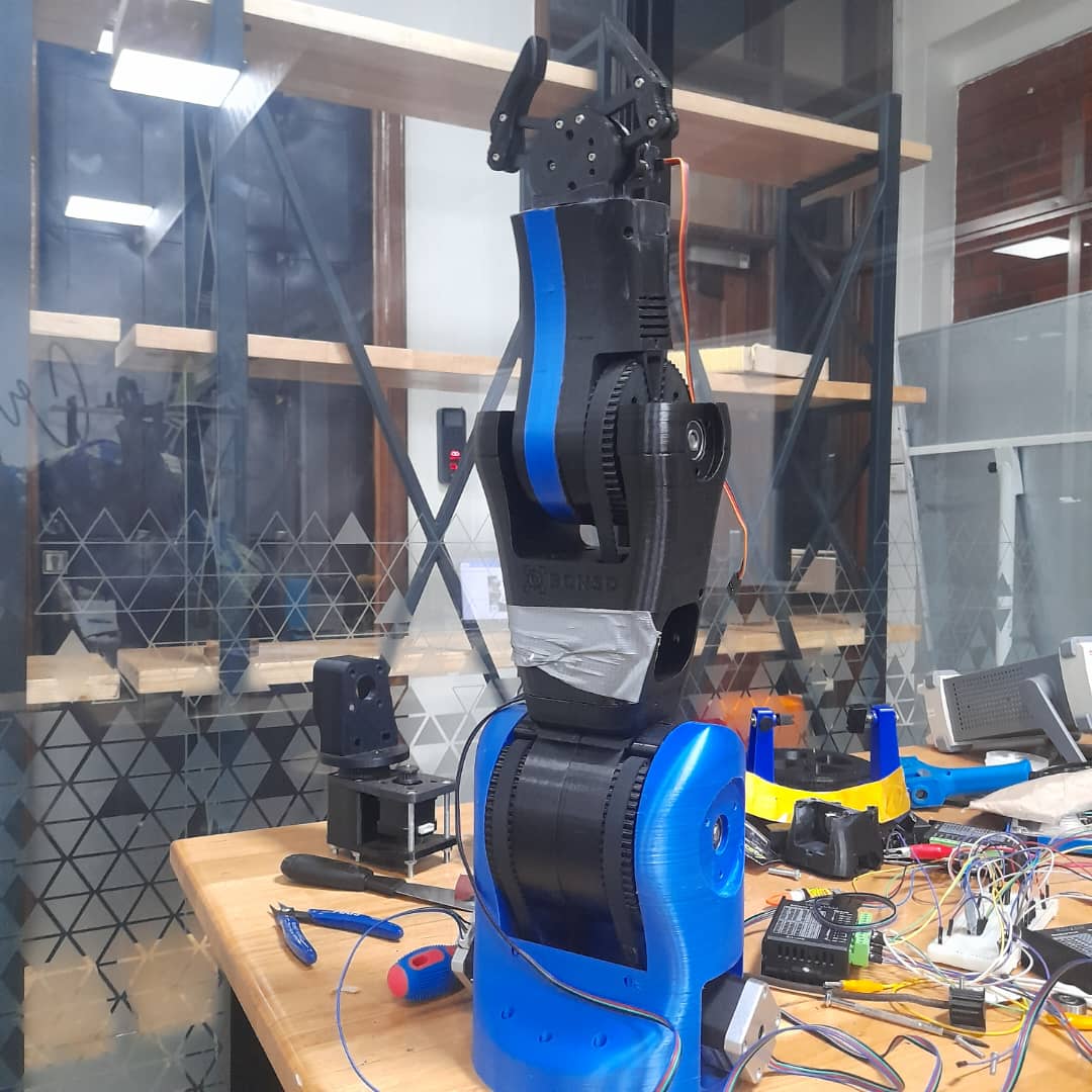
- Mounted motors and ensured structural alignment for smooth movement.
- Performed tuning and mechanical tests to verify joint performance.
- Control Interface Designing and firmware:
Interface preview
Firmware Code- Designed a manual control panel using Web serial communication.
- Mapped controls to microcontroller I/O pins for each axis.
- Labeled and tested the interface for usability and responsiveness.
The Core Features we Implemented:- Multi-axis stepper control via serial interface
- Angle-based motion mapping (0–180°) with step conversion
- Session-based position memory with support for save and playback
- Looped playback feature with adjustable timing between steps
- Motor reset function to bring all motors to 0°
Challenges- Serial Command Parsing: Since the interface was based on comma-separated strings, splitting and validating inputs reliably was critical to prevent misexecution.
- Angle to Step Conversion: Each motor used a specific number of steps per revolution, requiring custom scaling (e.g., 1° ≈ 5.68 steps for 28BYJ-48 with gear ratio).
- Position Memory: EEPROM was avoided to preserve lifespan, so all positions were stored in volatile memory during runtime and lost on power-off.
- Looped Playback Timing: Introducing a custom delay between motor sequences helped simulate coordinated movement but required precise state tracking.
- Safety Reset: A manual reset command was implemented to avoid mechanical overextension by returning motors to their safe base (0°) position.
-
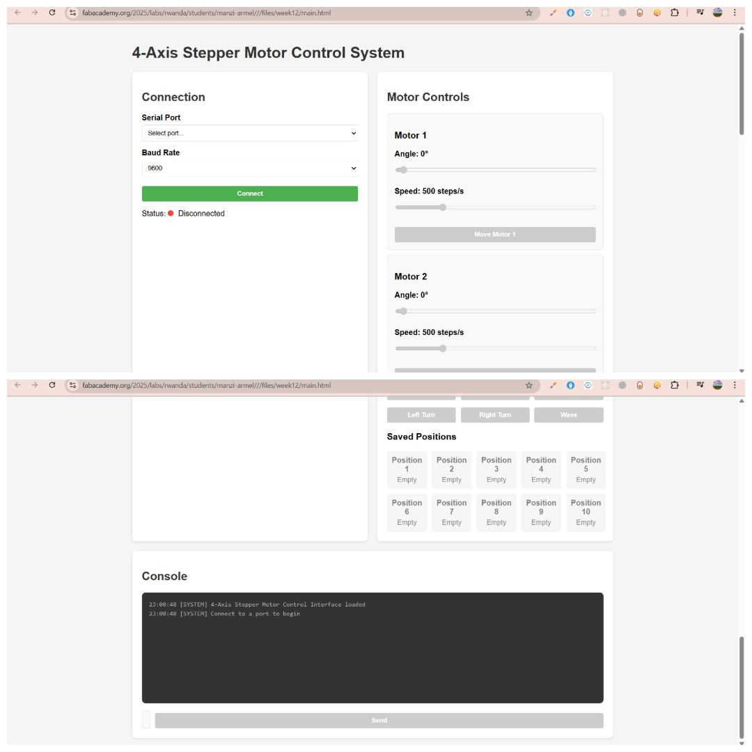
User Interface (UI) Overview
- Angle Adjustment: Set the desired motor angle using a slider.
- Speed Control: Define movement speed in steps per second.
- Move Command: A dedicated “Move Motor” button for each axis to execute commands.
The 4-Axis Stepper Motor Control System features a streamlined, web-based interface optimized for real-time motor control and precise position management. The interface is intuitive, responsive, and accessible via Wi-Fi, offering comprehensive control over each motor’s angle and speed.
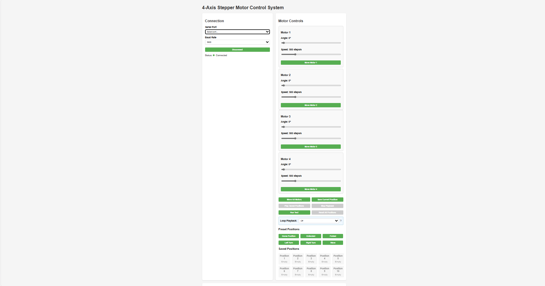
Main UI Sections 1. Connection PanelSelect a serial port and baud rate, then connect. Real-time connection status is shown using clear visual indicators.
2. Motor ControlsEach of the four stepper motors includes:
Quick-save and recall up to 10 preset motor positions. Custom labels such as “Left Turn,” “Right Turn,” and “Wave” help with easy identification and reuse.
4. Console OutputDisplays real-time system feedback, including command logs and status messages for monitoring performance and troubleshooting.
- Collaboration & Documentation:
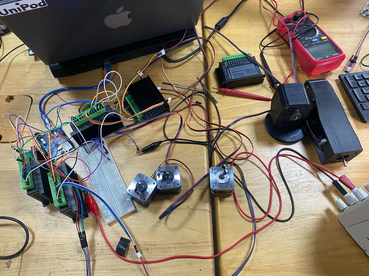
- Worked with the electronics team to wire and test the control panel.
- Participated in debugging and system integration.
What I have learned from this project.
Learning Outcomes 1. Mechanical Design & Fabrication- Learned how to design a multi-joint robotic arm with degrees of freedom for pick-and-place tasks.
- Gained experience in using CAD tools like SolidWorks for 3D modeling and Assembly.
- Developed hands-on skills in digital fabrication (3D printing, assembly).
- Understood mechanical constraints like torque, joint limits, and structural integrity.
- Learned to select suitable motors (stepper and servo) based on torque and precision requirements.
- Gained practical experience with stepper motor drivers.
- Understood the wiring and power requirements of a multi-motor system.
- Explored techniques for managing load and motor heat dissipation.
- Developed skills in embedded programming using Arduino/ESP32.
- Understood how to translate manual operations into automated sequences.
- Learned basic motion planning and joint coordination.
- Experienced how to combine mechanical, electrical, and software components into a working system.
- Understood debugging practices across subsystems mechanical misalignment, electrical faults,load balancing and code errors.
- Gained project management skills: planning, documentation, testing, and iterative improvement.
- Understood how robotic arms are applied in real-life scenarios such as manufacturing and lab automation.
- Reflected on the limitations of the current model and ideated improvements.
- Learned to operate the arm manually and compare its performance with the automated mode.
- Collaborated effectively in a multidisciplinary team by taking ownership of specific components.
- Practiced documenting work clearly for group reports and individual portfolios.
Files for codes Interface preview
Firmware Code