Week 7 assignment
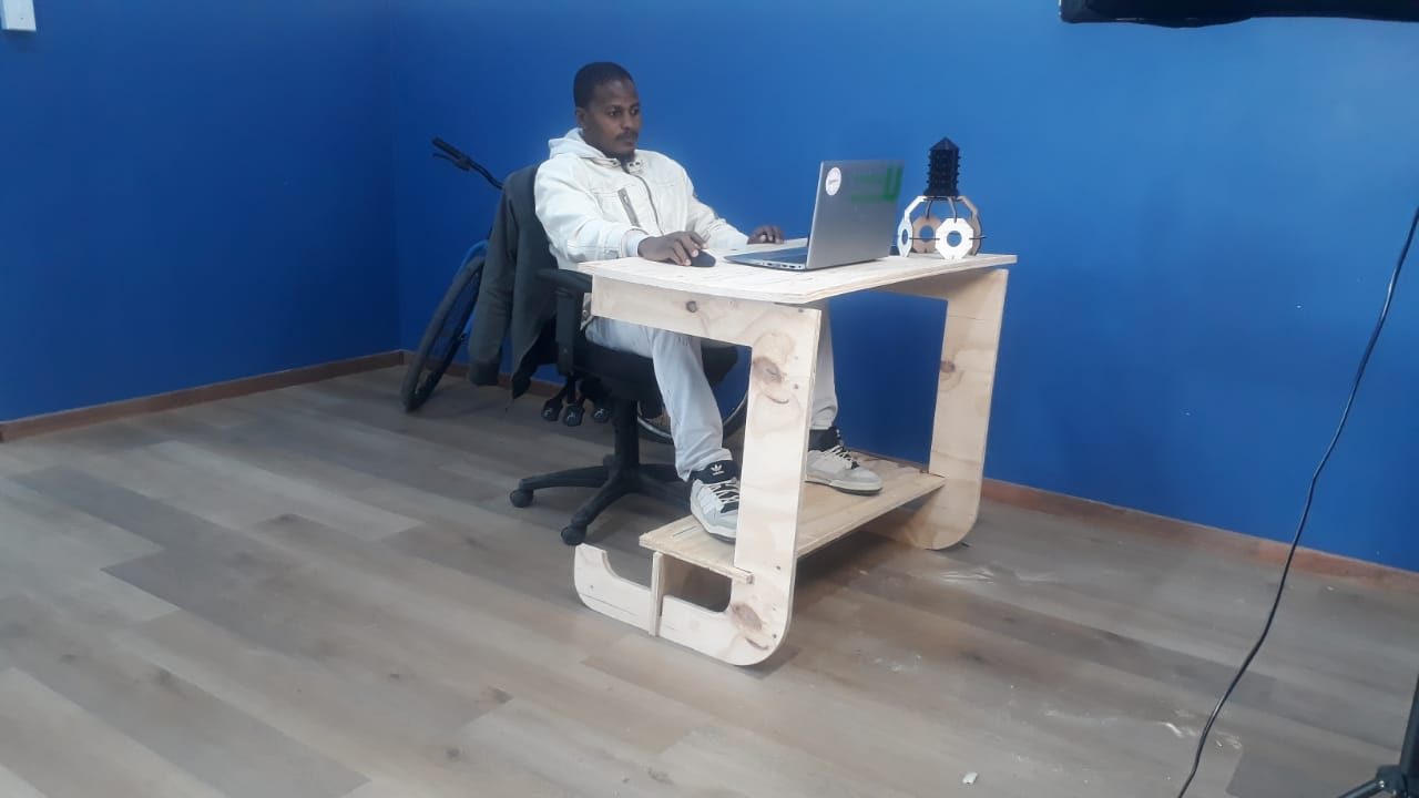
In this we covered computer controlled cutting, focussing on making something big that is combined using joints. I have designed a laptop table with foot rest that will produced using wood. I have designed it using SolidWorks as the designing tool and created 3D parts that will provide a final view of the table. The part will be produced using CNC router and be assembled using the joints.
This is the link for group assignment: Group assignment
Individual assignment
To design in SolidWorks, I opened the application and created new part from the display. This is where the project for the parts will be handled.
Select part.
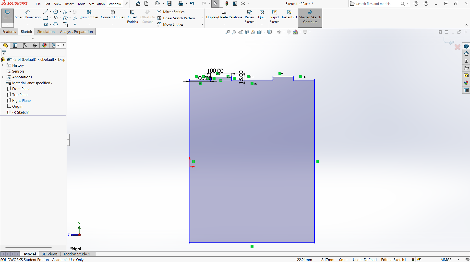
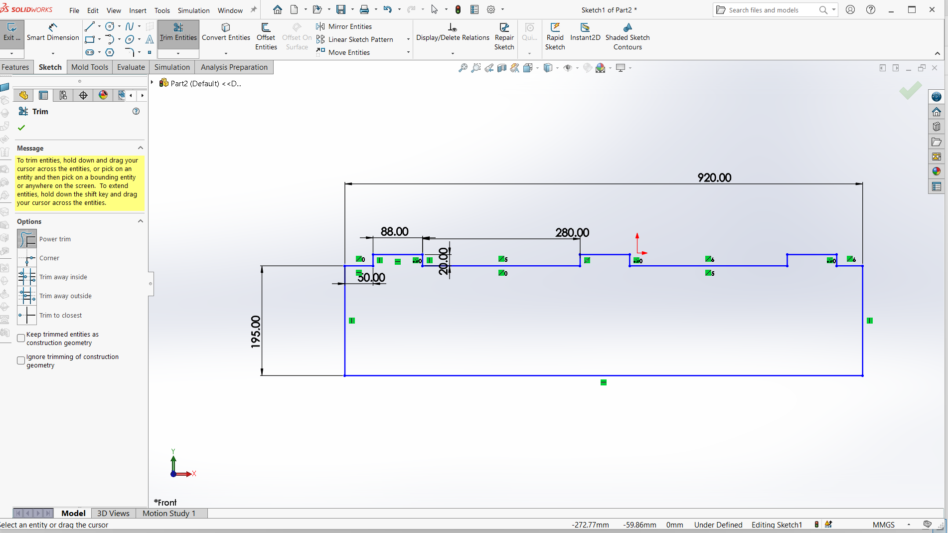
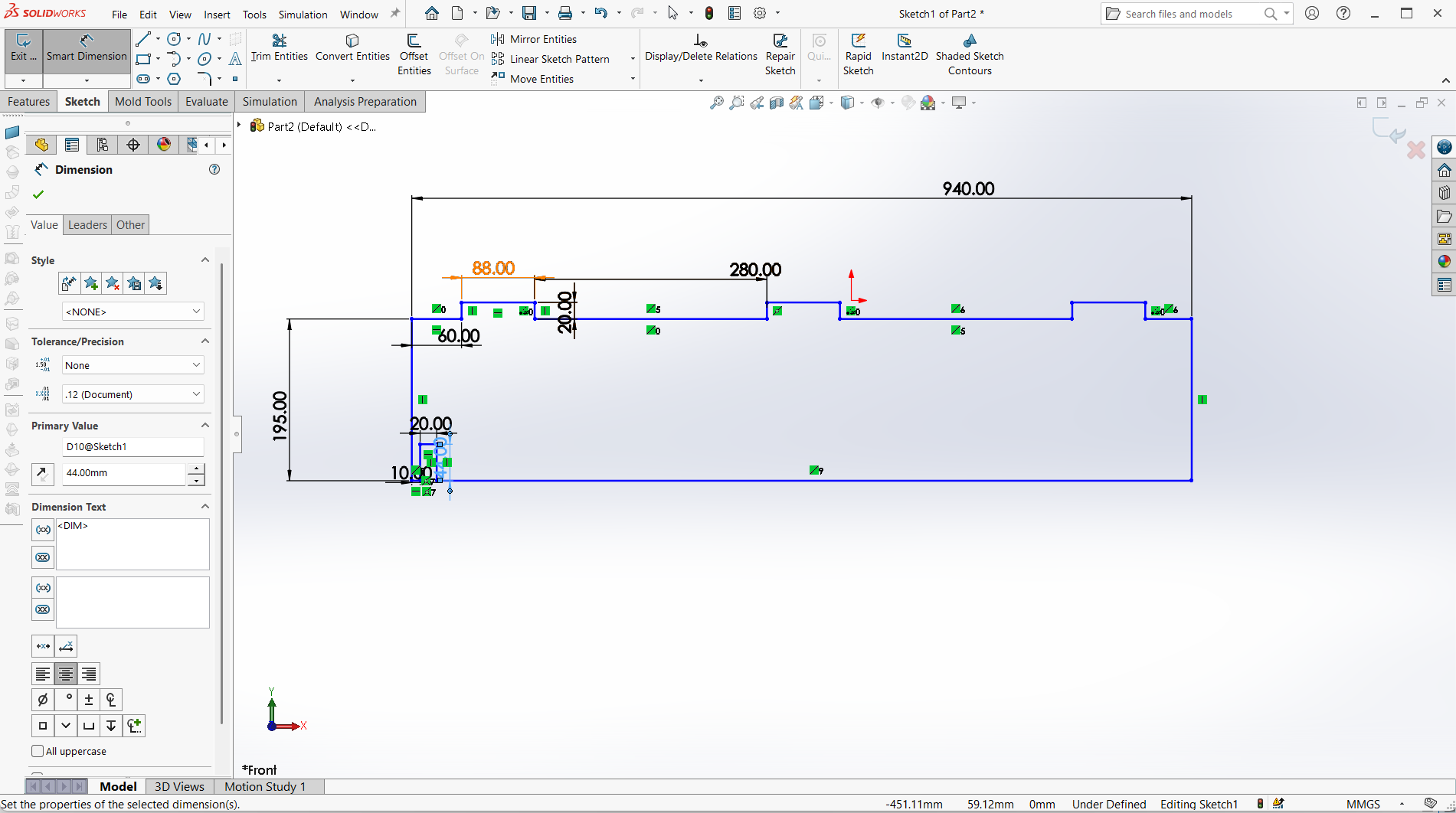
Below is the design of the legs which is designed in way to fit to the respective joints. The joint depth is 10mm, width is 100mm. Some measurements are shown on picture below.
Creating joints
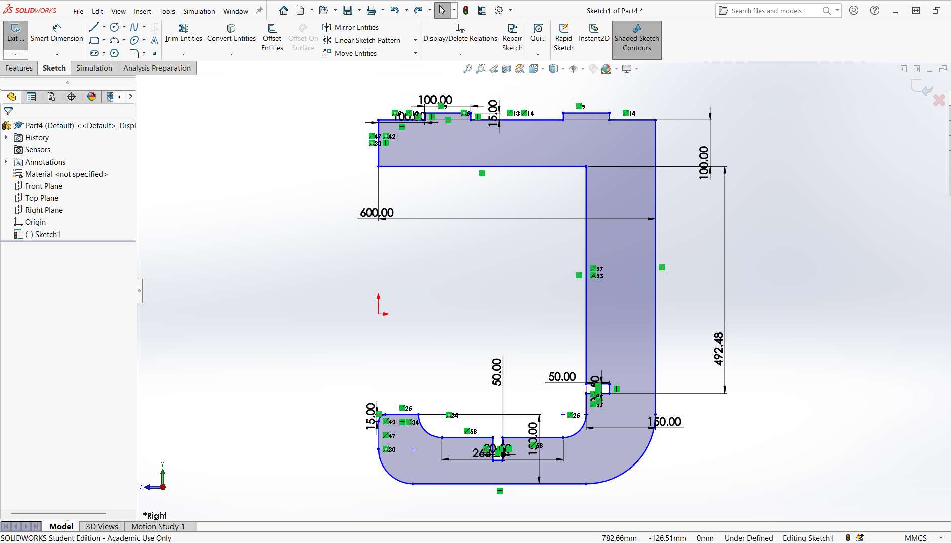
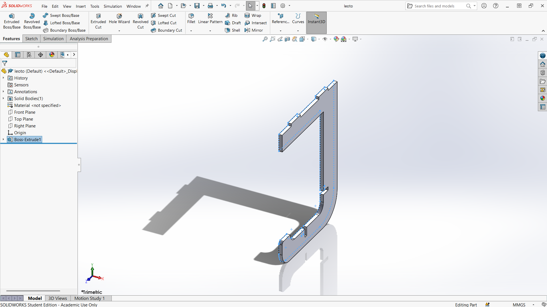
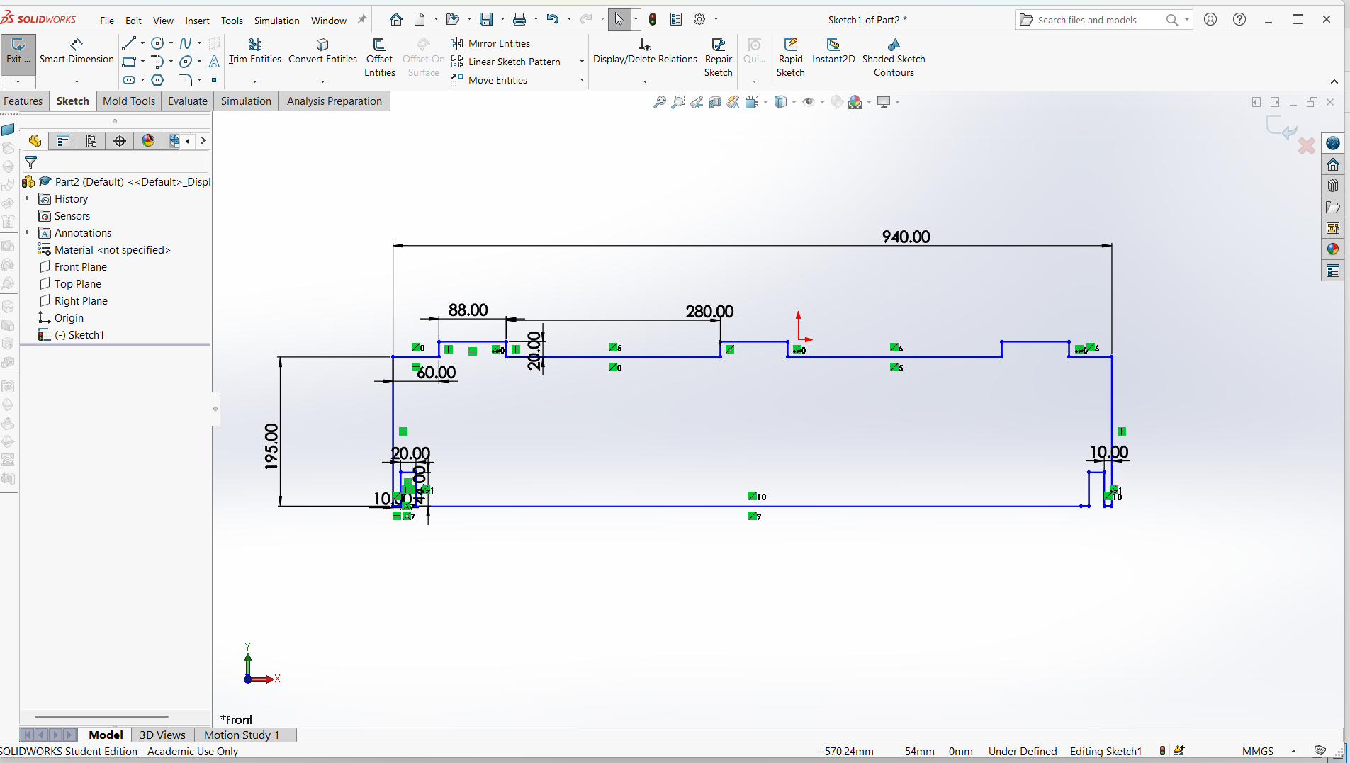
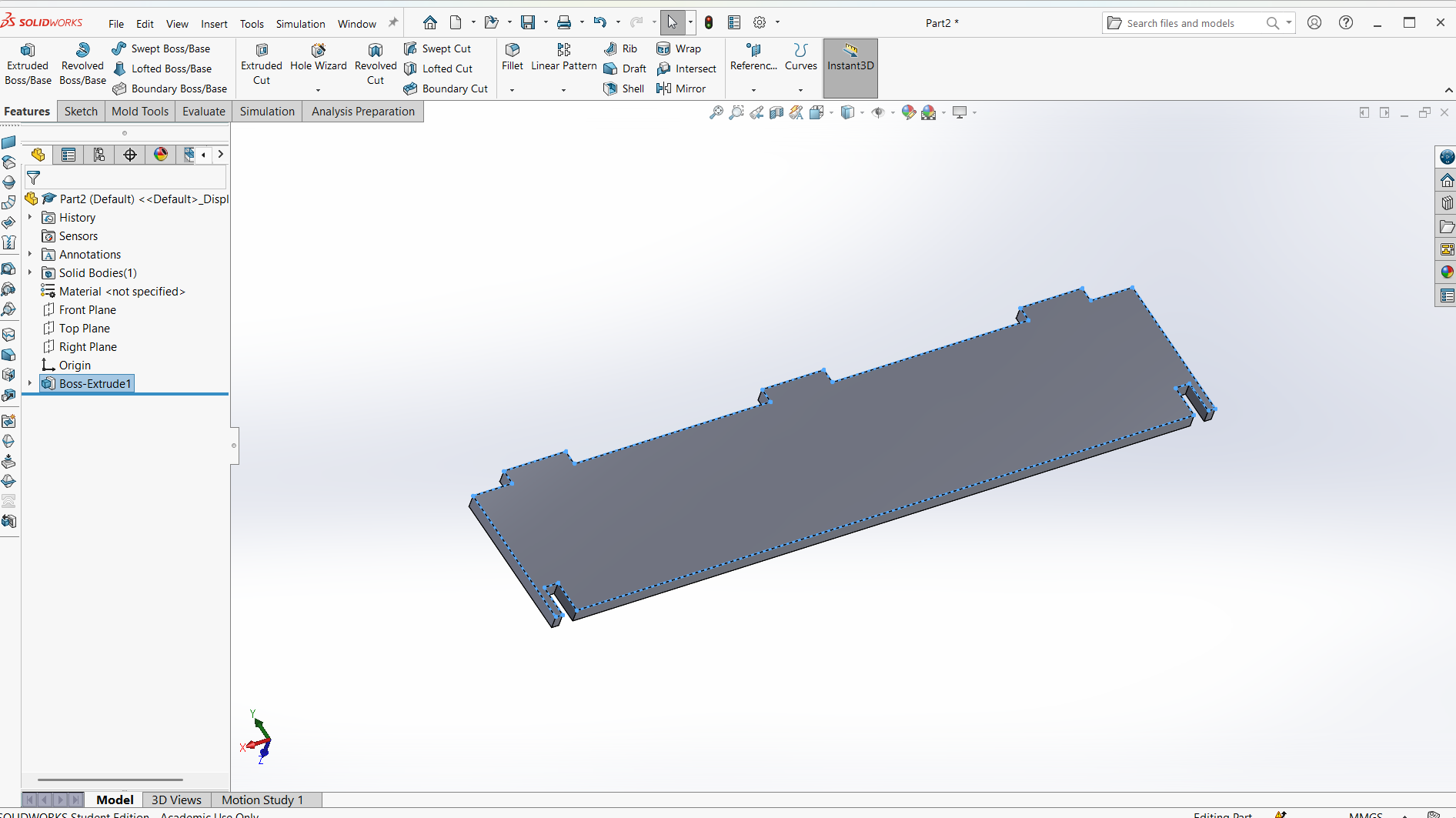
Final leg.
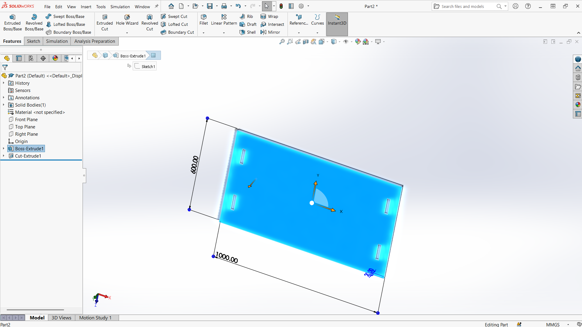
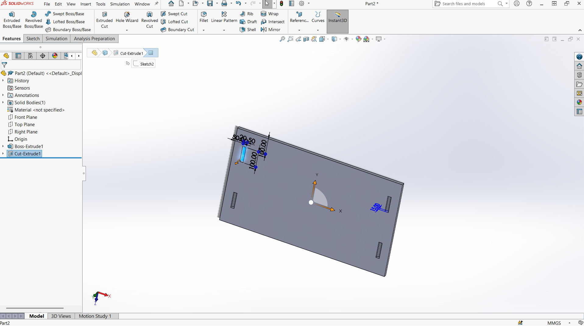
Top
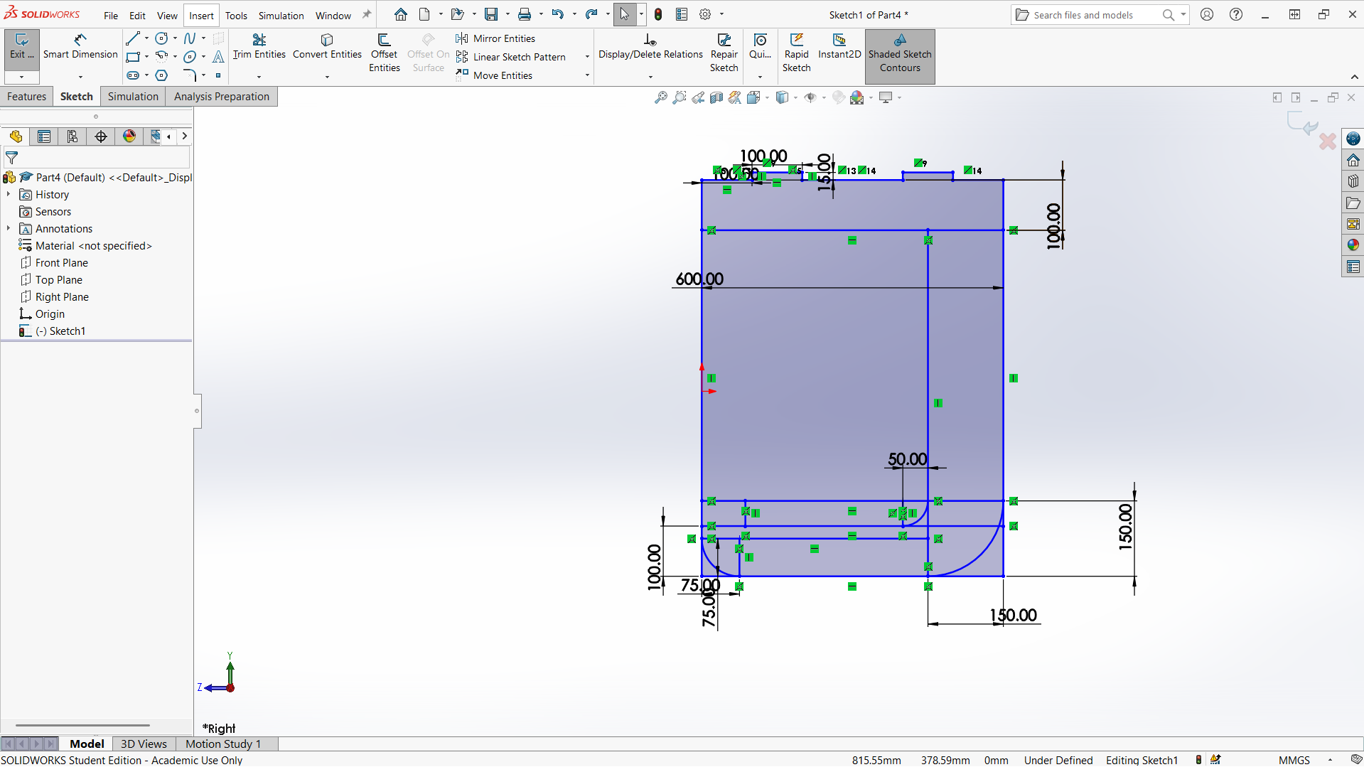
Creating top with length of 1000mm and width of 600mm. The depth of the joint is also 15mm to allow the leg joint fit well. The width of the joint is 20mm for smooth joining.
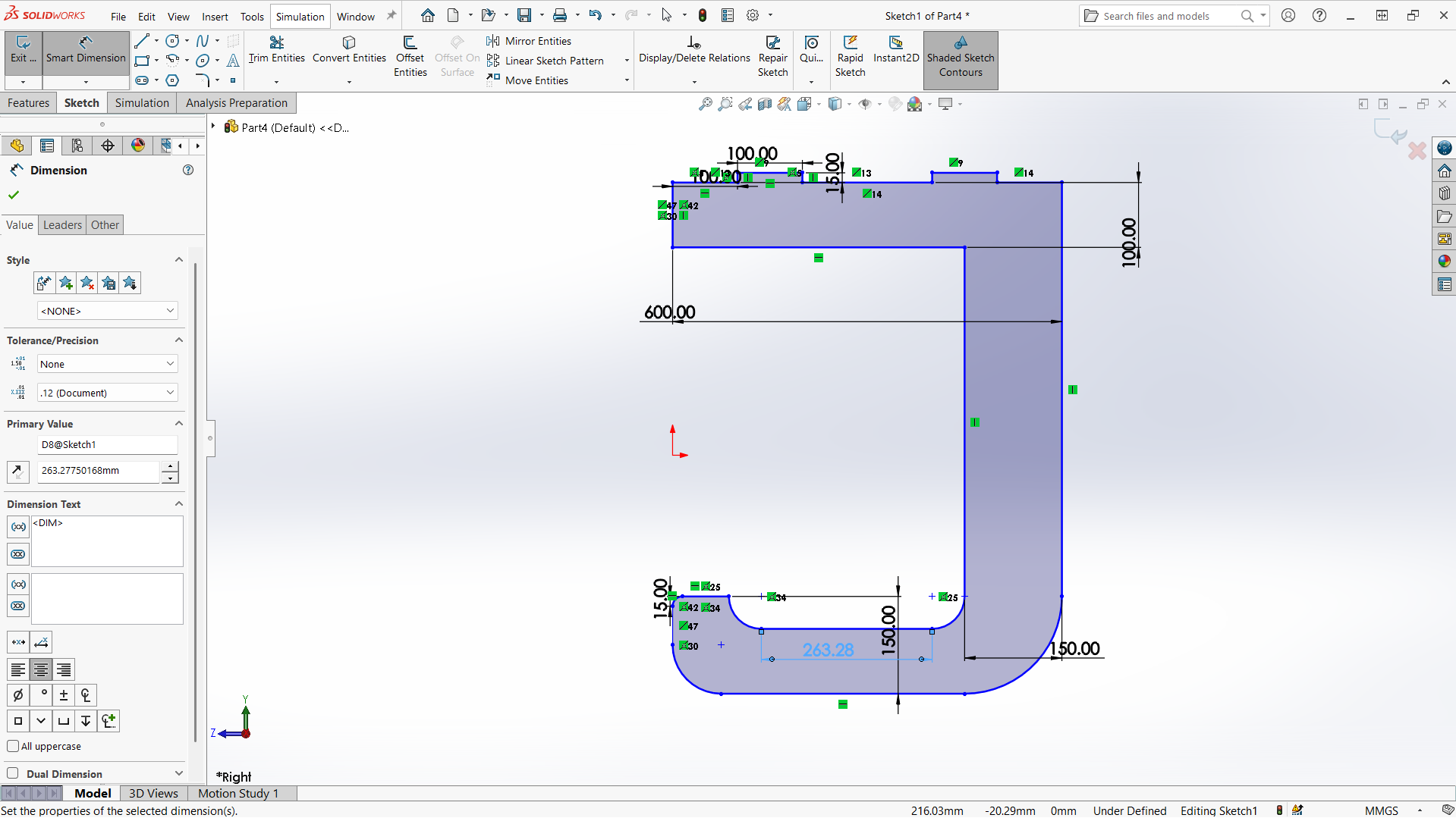
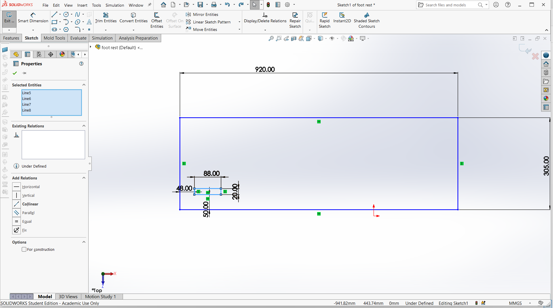
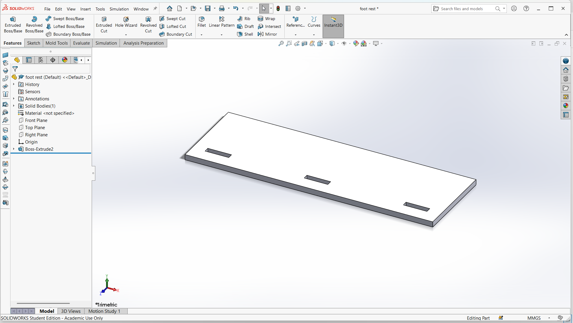
Foot rest
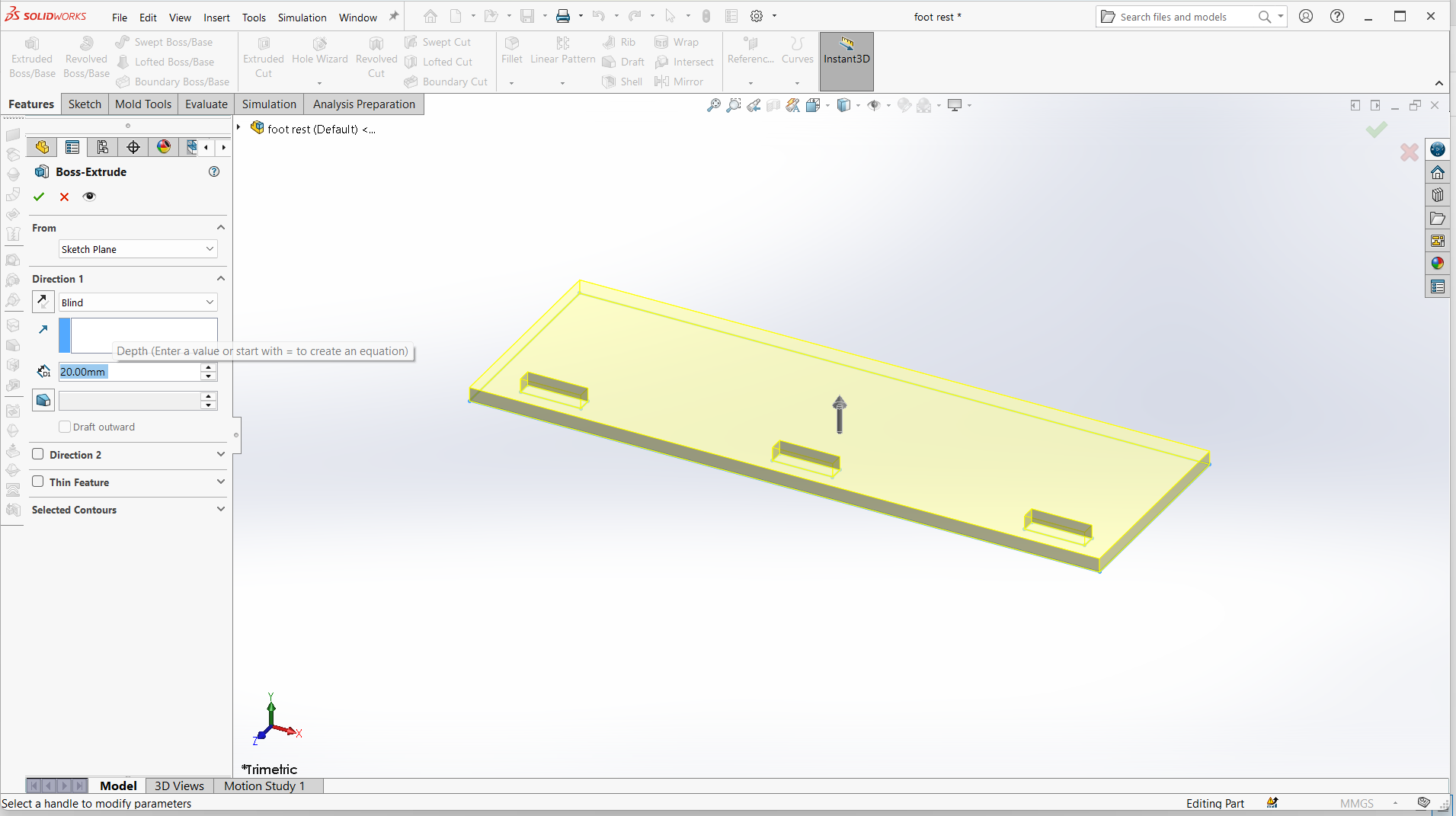
Foot rest is designed using top and support for the foot rest.
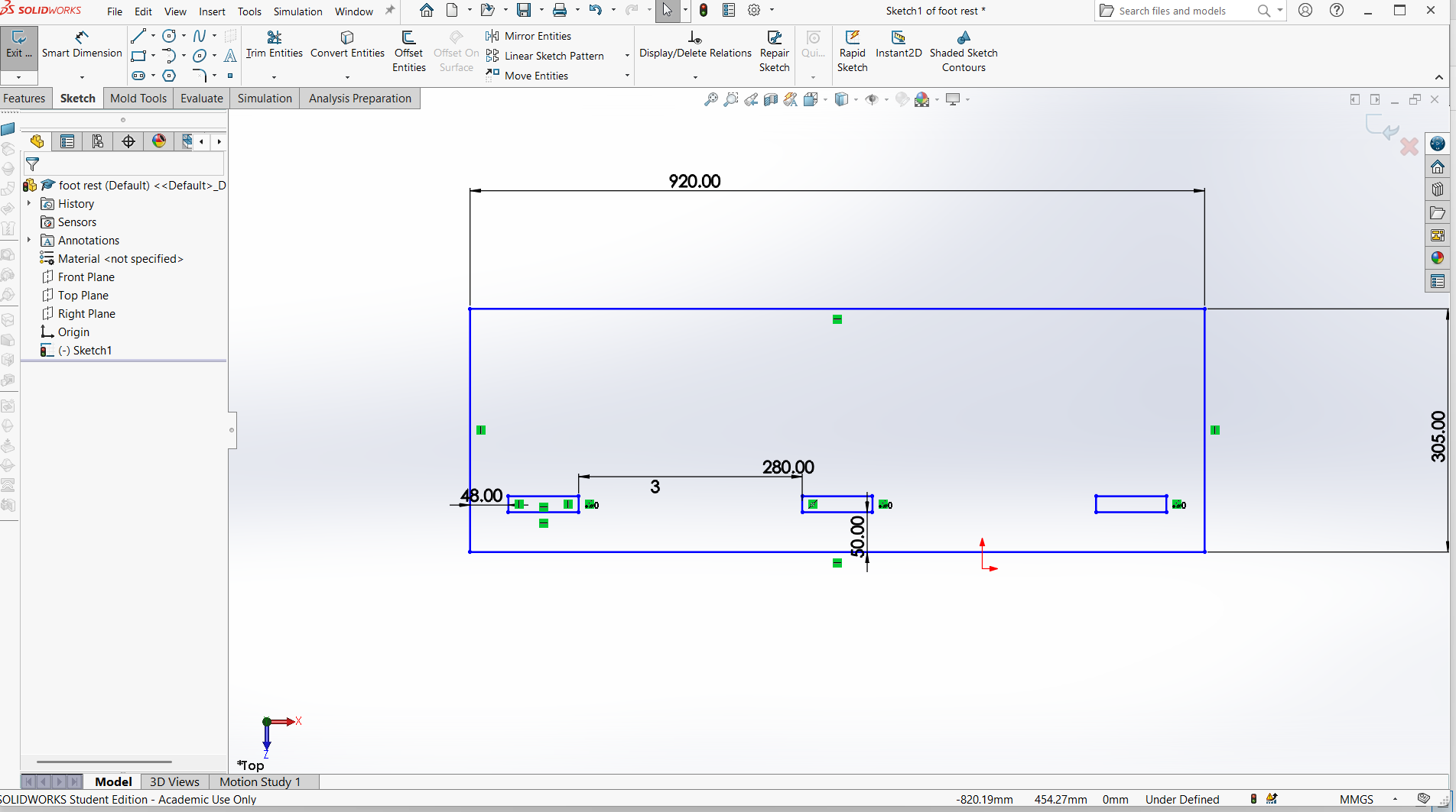
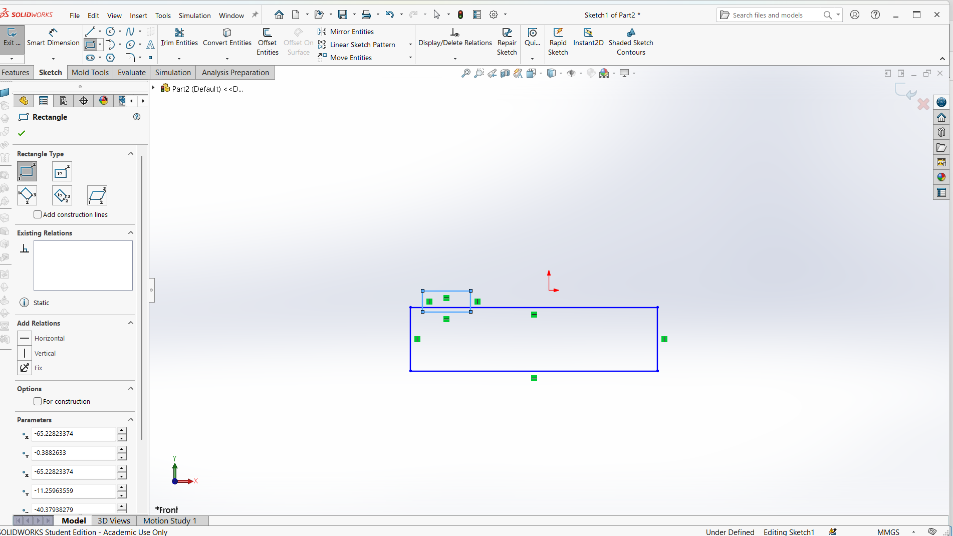
I have designed using rectangle tool to design both top and support with tabs and joints.
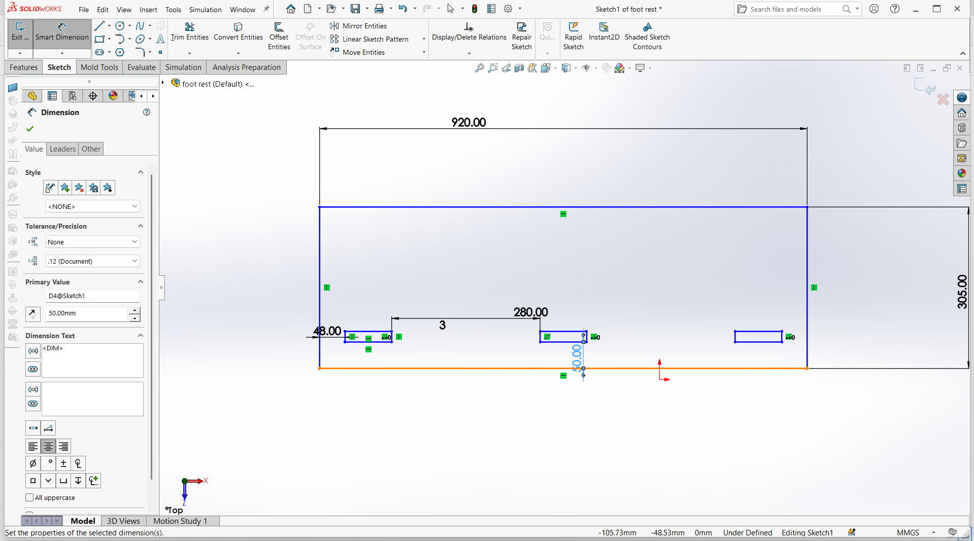
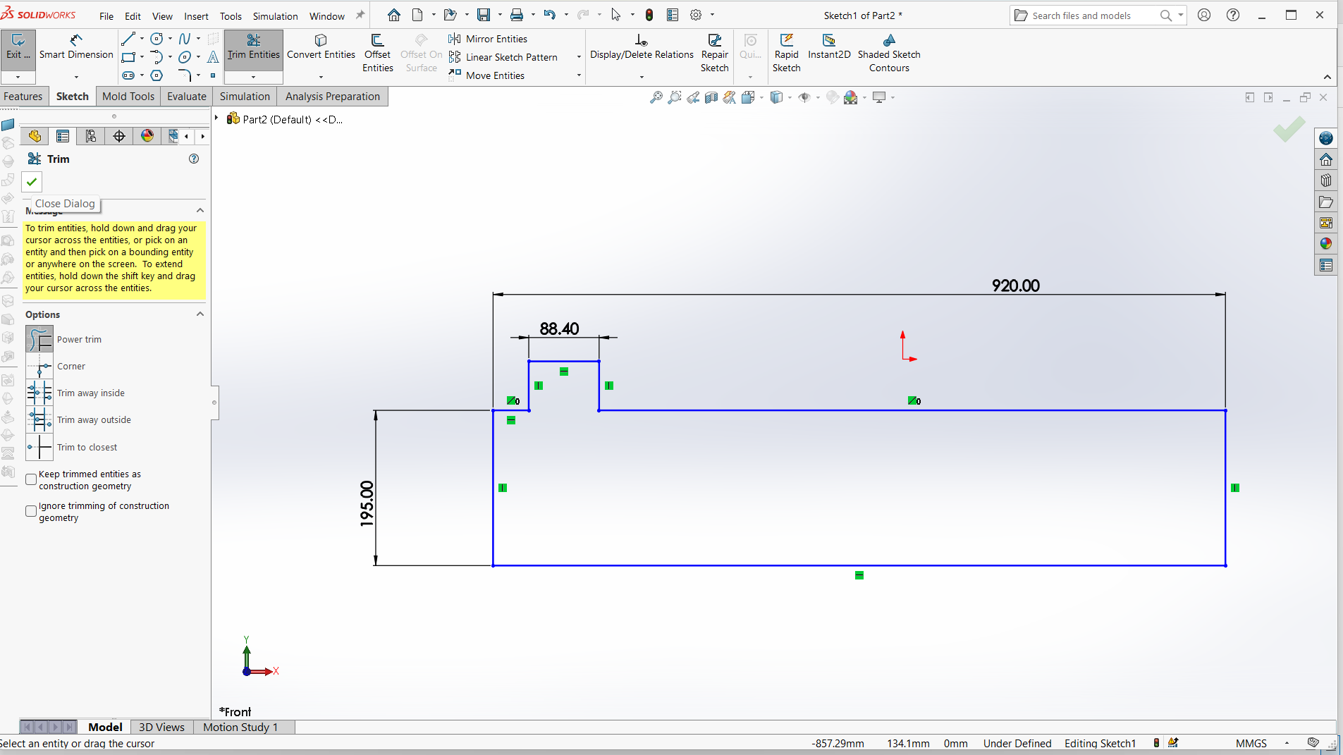
Made small for the pocket hole and the tabs to join.
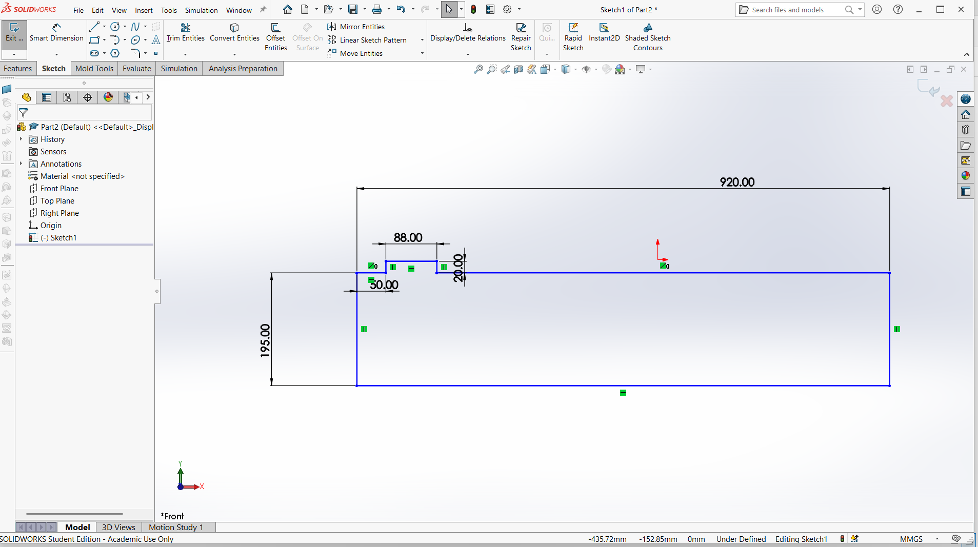
Trim the unwanted line to make one object.
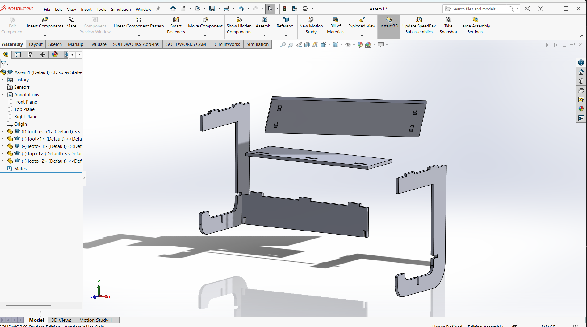
Assembling parts from designs.
In SolidWorks, an assembly is a file type (.SLDASM) that allows you to bring together multiple parts (.SLDPRT) to create a functional product or mechanism.
Assemblies let you define how parts fit and move relative to each other using mates, and they can include sub-assemblies (assemblies inside assemblies).
Basic Steps to Create an Assembly in SolidWorks
1. Start a New Assembly
- Go to File > New > Assembly.
- Choose your template and click OK.
- Click Insert Components from the CommandManager or go to Insert > Component > Existing Part/Assembly.
- Browse to and select the part(s) you want to insert.
- Click to place the component into the graphics area.
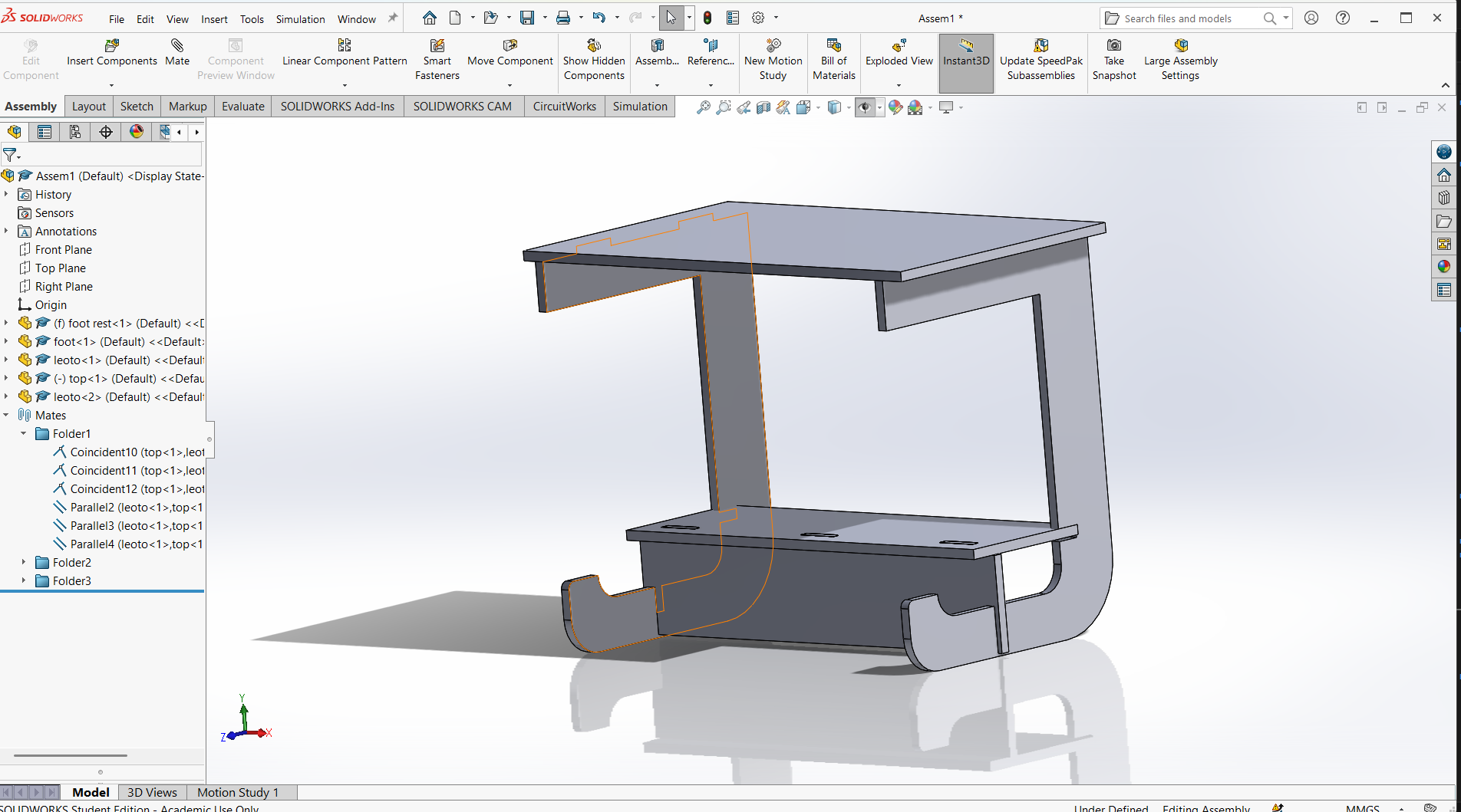
Mates define how components are aligned and connected. Use Mate from the Assembly toolbar.
Common mates:
- Coincident: Faces, edges, or planes touch each other.
- Concentric: Cylindrical features share the same center.
- Distance: Sets a fixed gap between components.
- Angle: Fixes an angle between parts.
- Use the Move Component or Rotate Component tools to adjust parts before mating.
- Dynamic dragging helps to test motion and find conflicts.
- You can create an assembly from parts, save it, and insert it into another assembly.
- This helps manage complexity and organize your design.
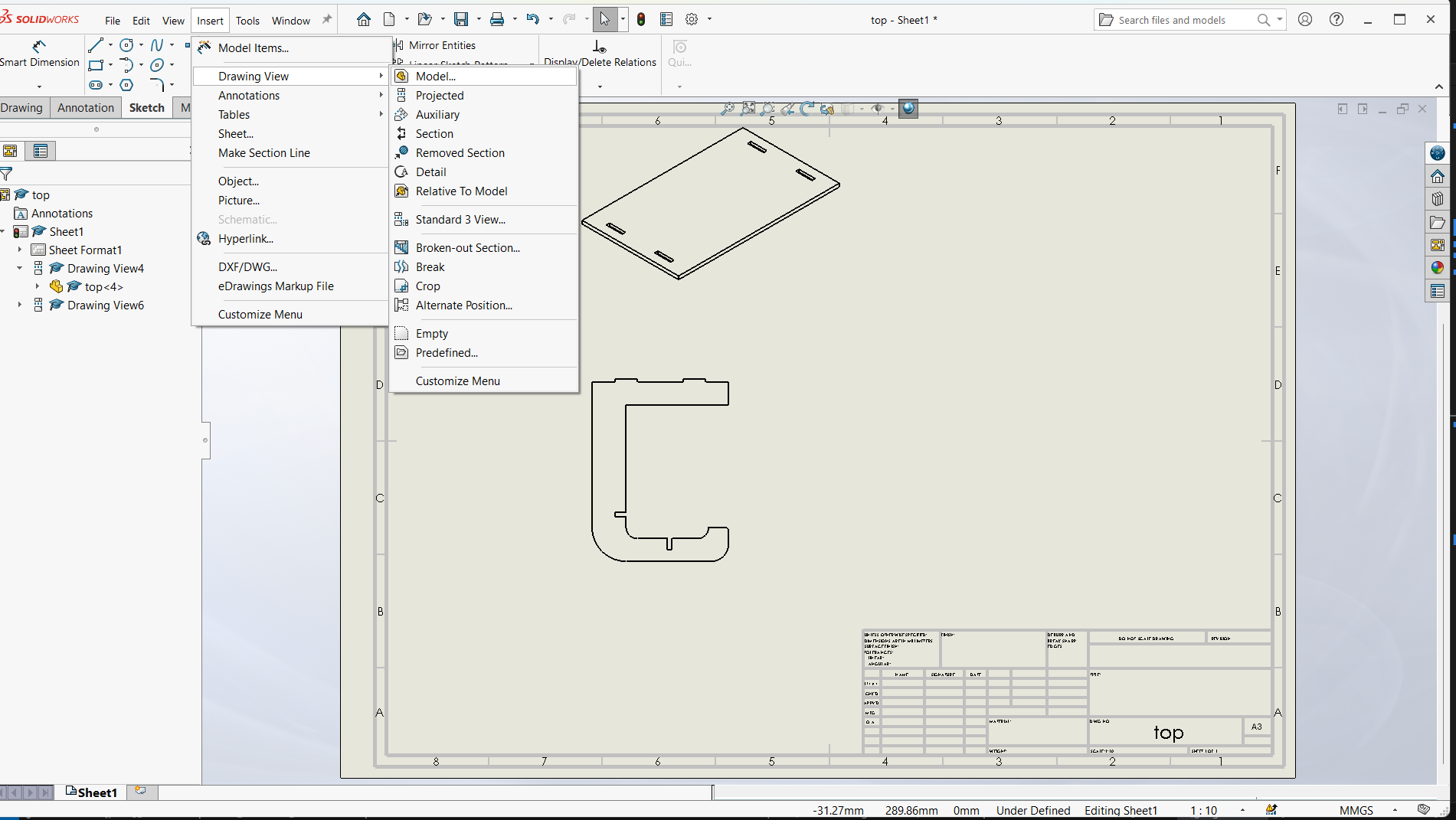
Export DXF from a Drawing View
Steps to follow
- Create a Drawing:
- Go to File > New > Drawing
- Select a drawing
- Select sheet format/size
- Go to view model, then browse to select the parts
- Drop on the work space of the sheet
- Save the Drawing as DXF:
- Go to File > Save As > DXF
- Choose what views or sheets to include
- Click Save
- Launch Aspire.
- Click "Create a New Project".
- Set your material size, thickness, and Z-zero position (top or bottom of material).
- Import vectors/images (SVG, DXF, PDF, bitmap for tracing).
- For 3D carving, import or create 3D models as components.
- Switch to the Toolpaths tab on the right sidebar.
- Click "Set Material" to confirm material settings.
- Profile Toolpath – Cut along vector lines (inside/outside/on).
- Pocket Toolpath – Clear areas inside closed vectors.
- Drilling Toolpath – For simple vertical hole drilling.
- V-Carve / Engraving Toolpath – For detailed text or engraving.
- Inlay Toolpaths – For precision-fit parts.
- Roughing Toolpath – Removes bulk material.
- Finishing Toolpath – Fine, detailed pass for 3D models.
- Moulding Toolpath – Along a 2D profile with a 3D shape.
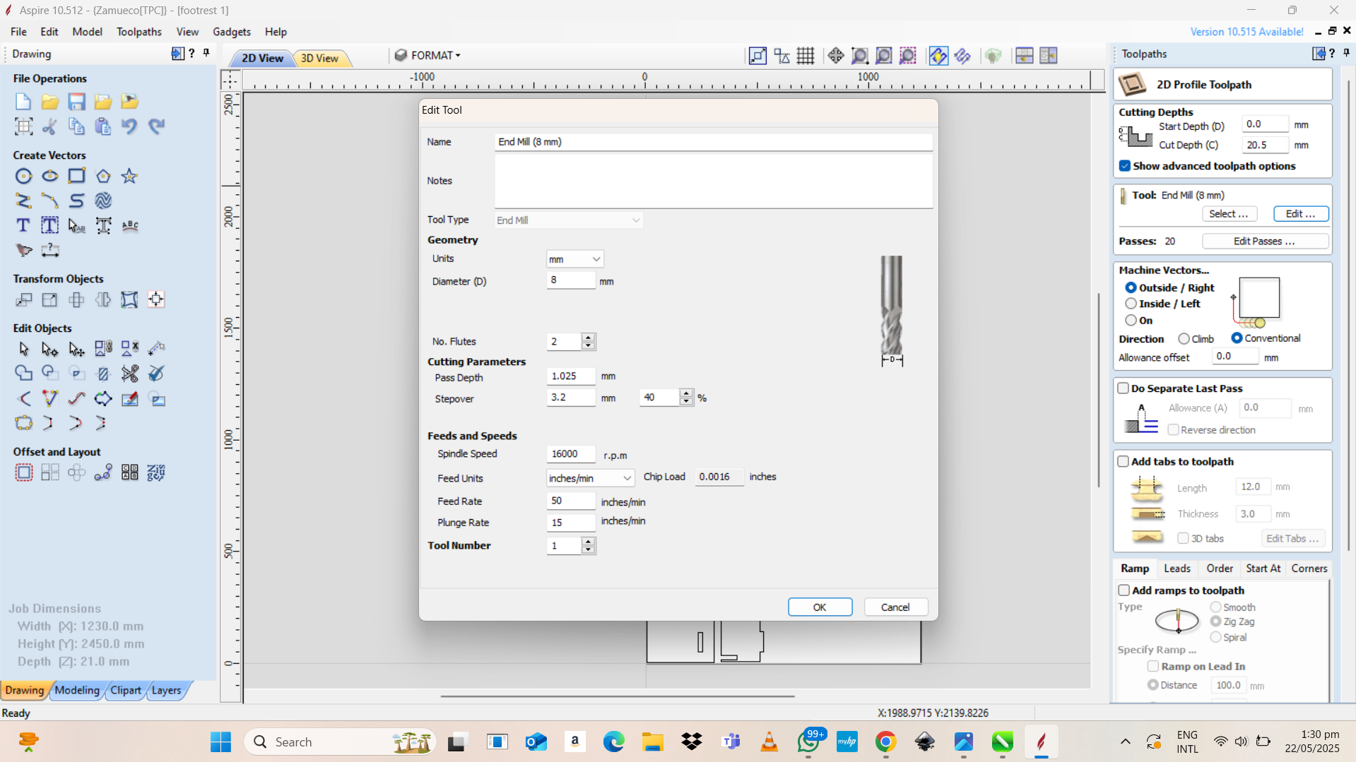
- Select a tool from the tool database (e.g., end mill, ball nose).
- Set parameters:
- Cut depth (20.5mm)
- Pass depth (20mm)
- Feed rate (1.025)
- Spindle speed (16000)
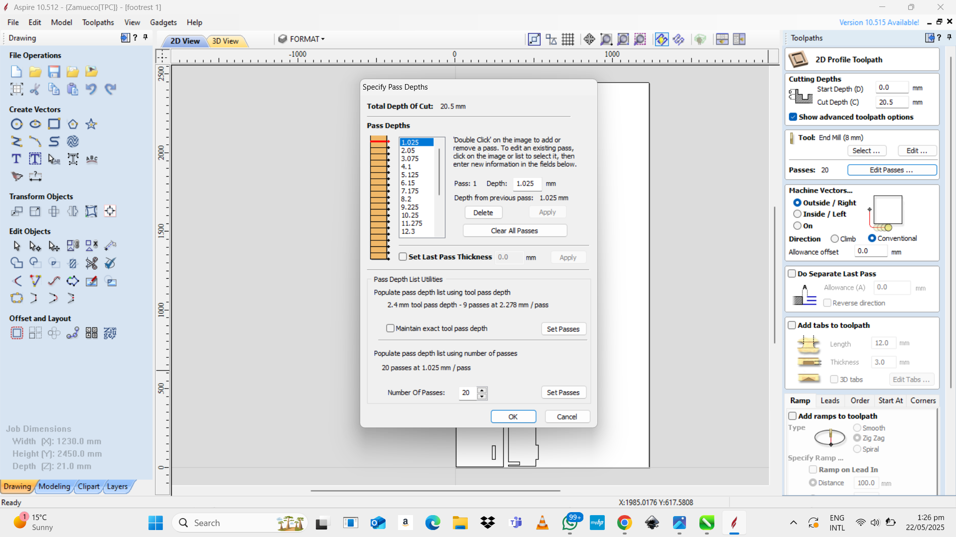
- Add tabs if needed (to hold cut-out pieces in place).
- Use ramping or leads for smoother cuts.
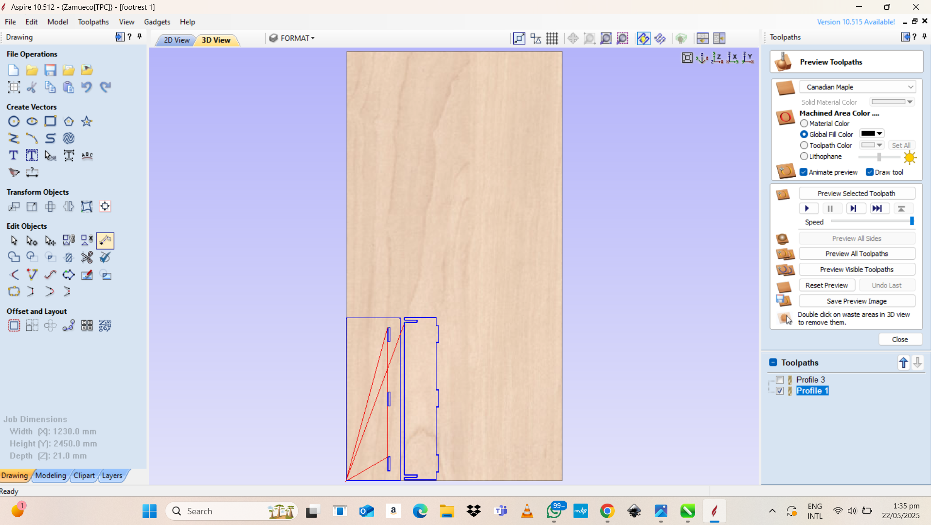
- Click "Preview Toolpath" to simulate the cutting.
- Adjust as needed if the results are not satisfactory.
- Click "Save Toolpath".
- Select your post-processor (depends on your CNC machine).
- Save the file in the appropriate format (e.g.,
.tap,.nc, etc.).
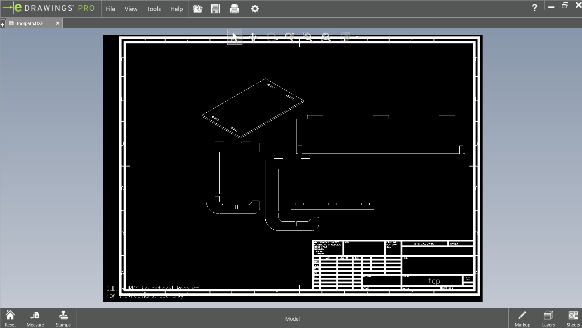
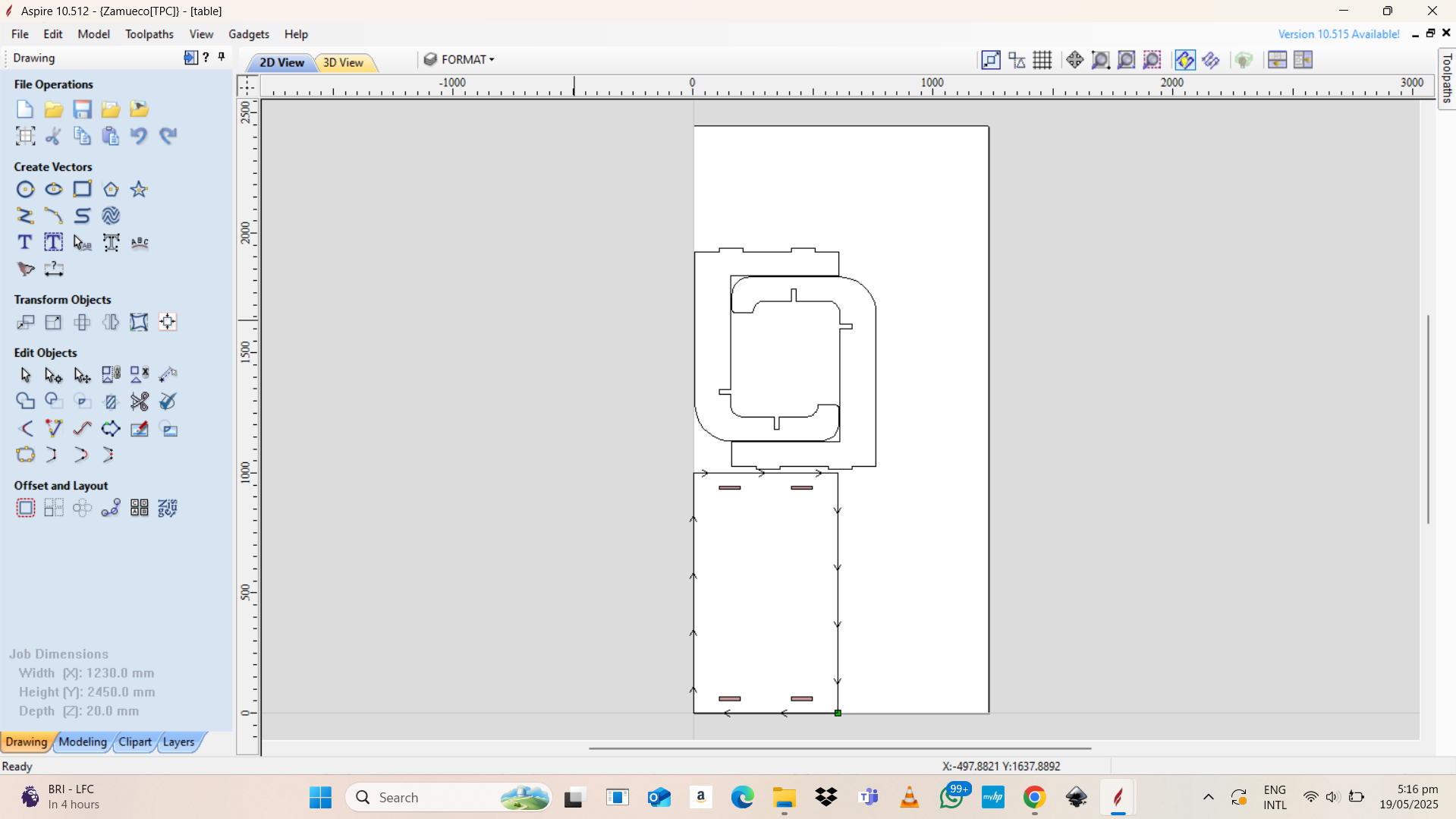
After I have saved the file in .dxf file to be used to create the tool-path in Aspire.
Aspire is a software that brings together all of the 2D & 2.5D tools and functionality available in Cut2D and VCarve with added 3D design tools enabling you to create 3D relief models and machine them with 3D machining strategies.
Aspire is the software that I used to generate the g-code for CNC router for cutting.
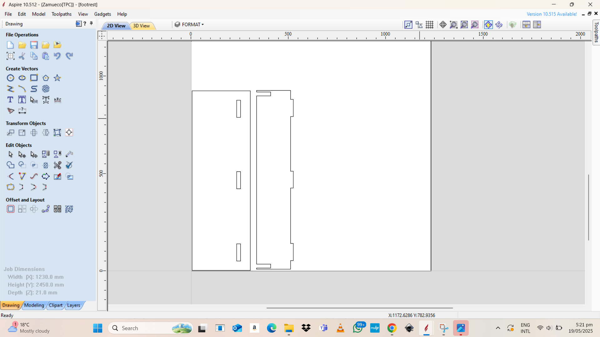
I imported the .dxf file into Aspire then selected the joint where the CNC machine will engrave and cut.
Steps to generate g-code and toolpath in Aspire
How to Generate Toolpaths in Aspire
1. Start a New Project
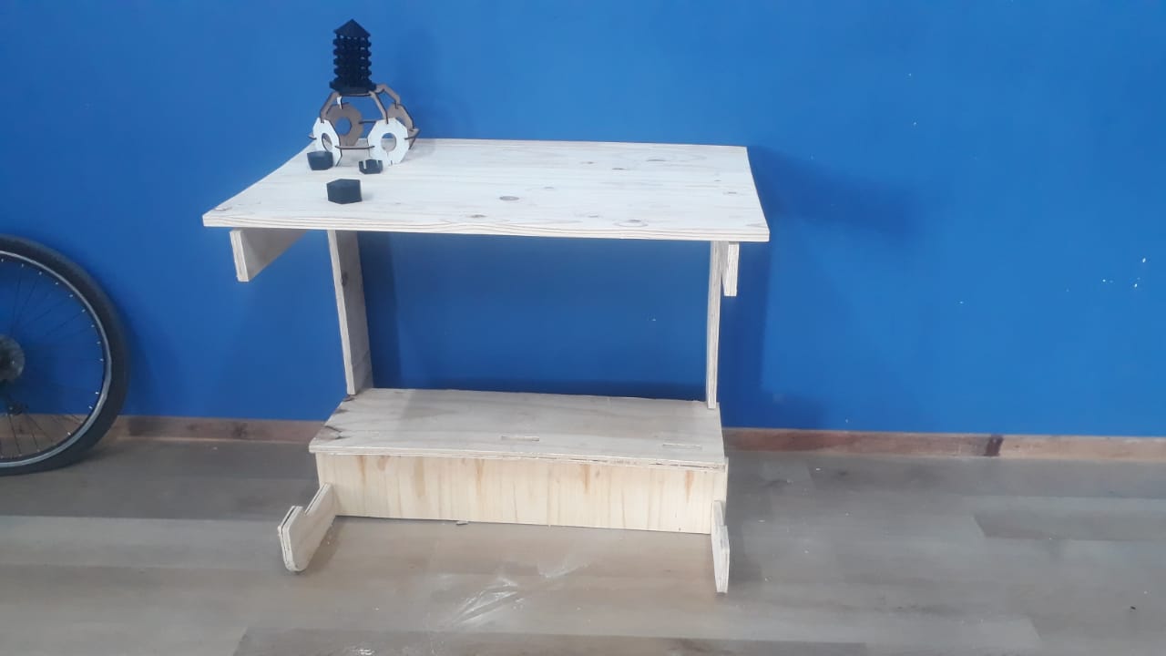
Final product
Below are the design files for the parts
Foot rest topFoot rest support
Table Foot
Table Top
Table Assembly