3D Printing and Sacnning
In this page there is a link for the week 5 group assigment which is on 3D printing and scanning.
The purpose was to test the design rules for the 3D printers we have. I have made a dsign rules for printer in the lab.
Group assigment
Individual Assignment
Design and 3D print an object (small, few cm3, limited by printer time) that could not be easily made subtractively
Matrix Lattice Design and 3D Printing Using FreeCAD
In this section, I present how I used FreeCAD to design a customizable lattice matrix structure suitable for 3D printing. The aim was to explore how to make object that is not easy to make subtractively.
I began the design process in FreeCAD by selecting the Part Design Workbench. Here’s the step-by-step breakdown:
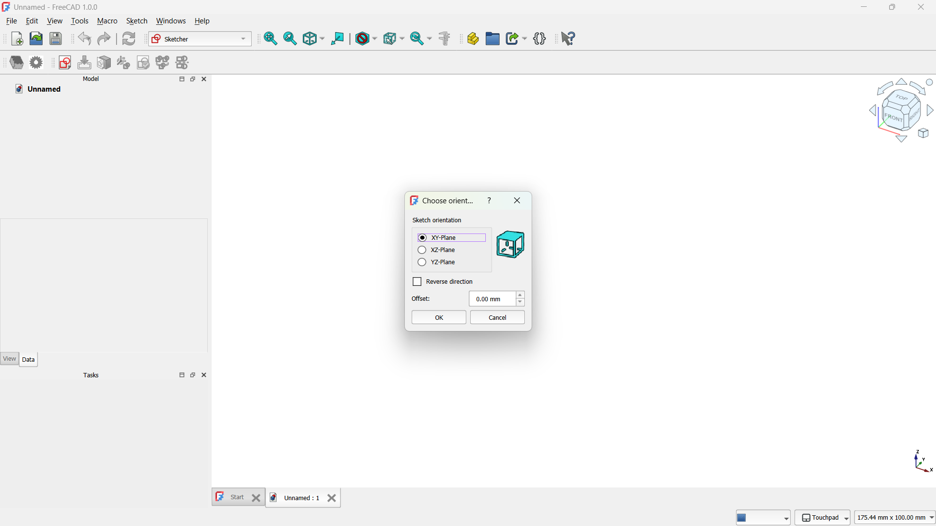
- Step 1: Create a New Body and Sketch
- Click Create New and select the Part Design workbench.
- Create a new body and then a new sketch on the XY plane.
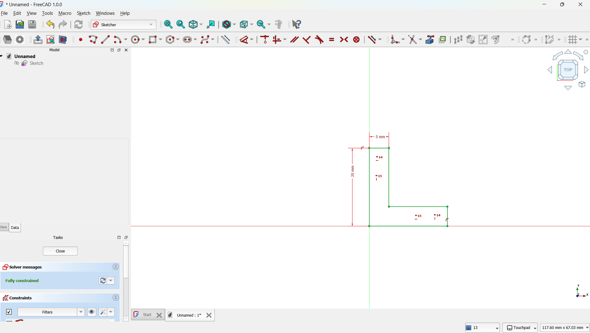
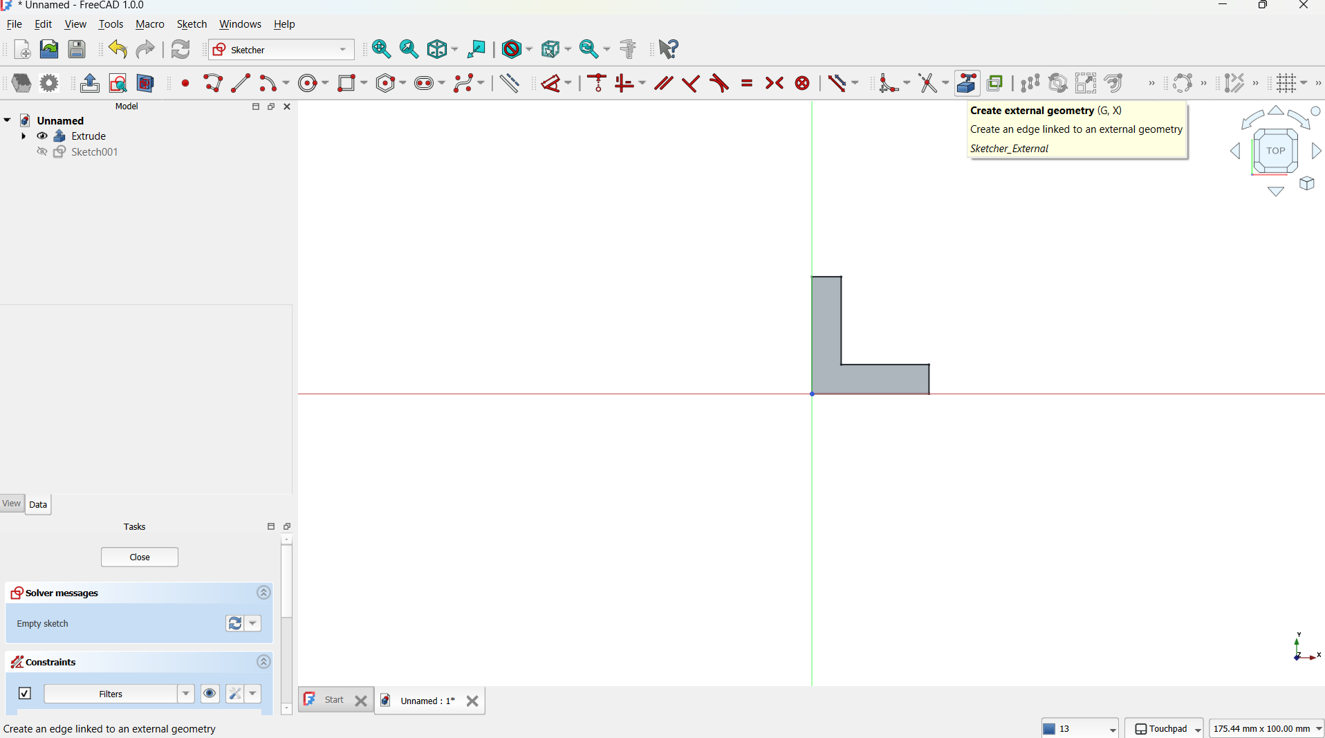
- I drew a simple "L" using polyline tool which served as the unit cell of the lattice. This shape was fully constrained using dimension and symmetry tools. - Step 2: Pad the Sketch into 3D
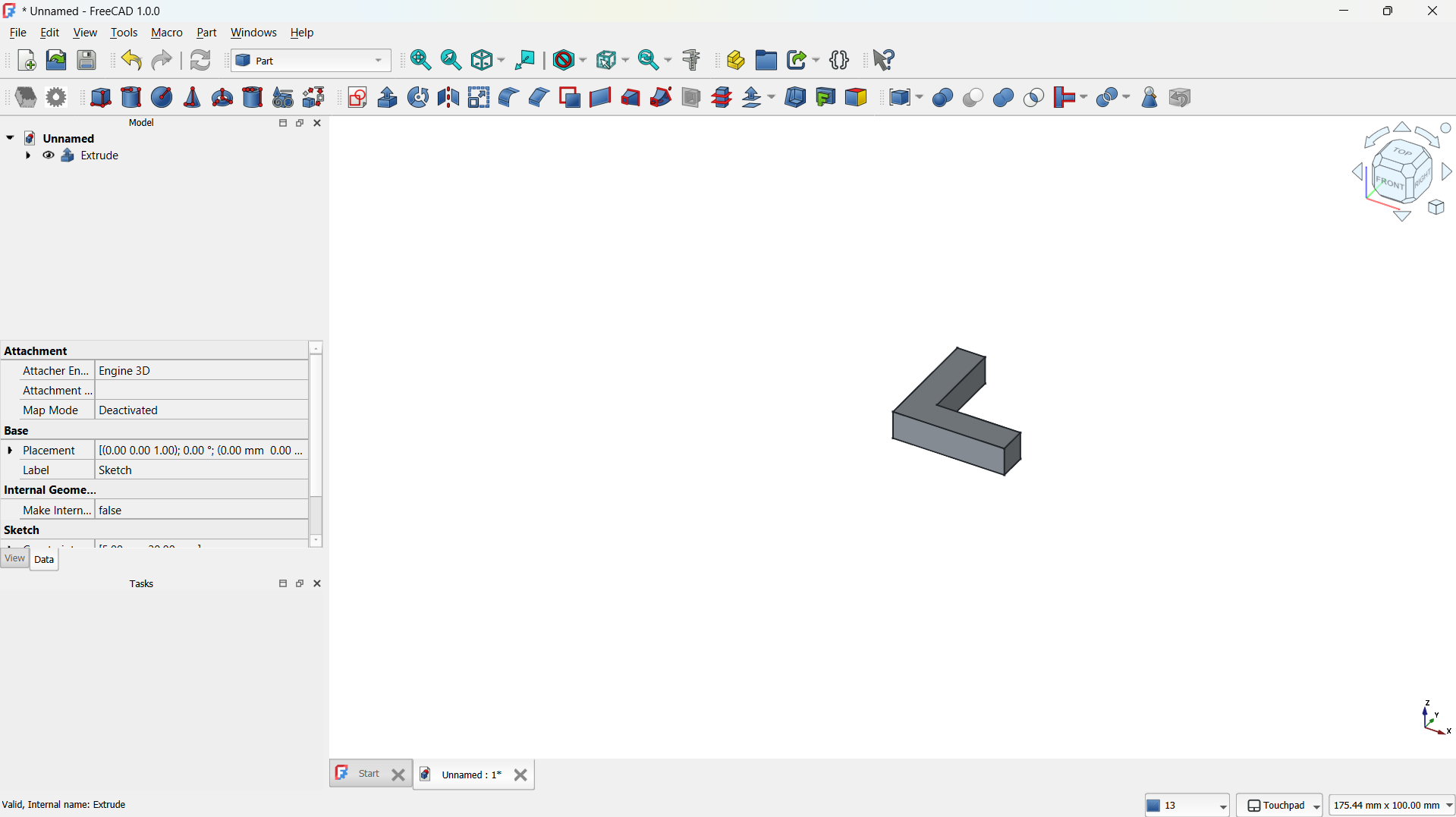
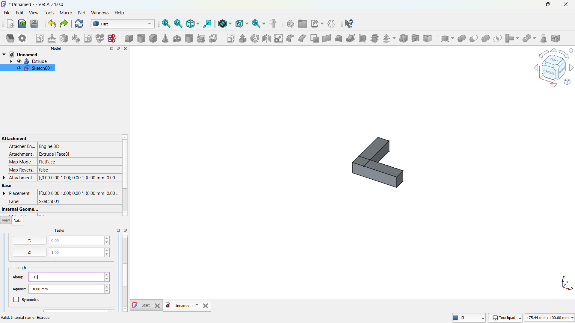
- I used the Extrude tool to extrude the sketch to a desired thickness (e.g., 5 mm), transforming the 2D shape into a 3D object.
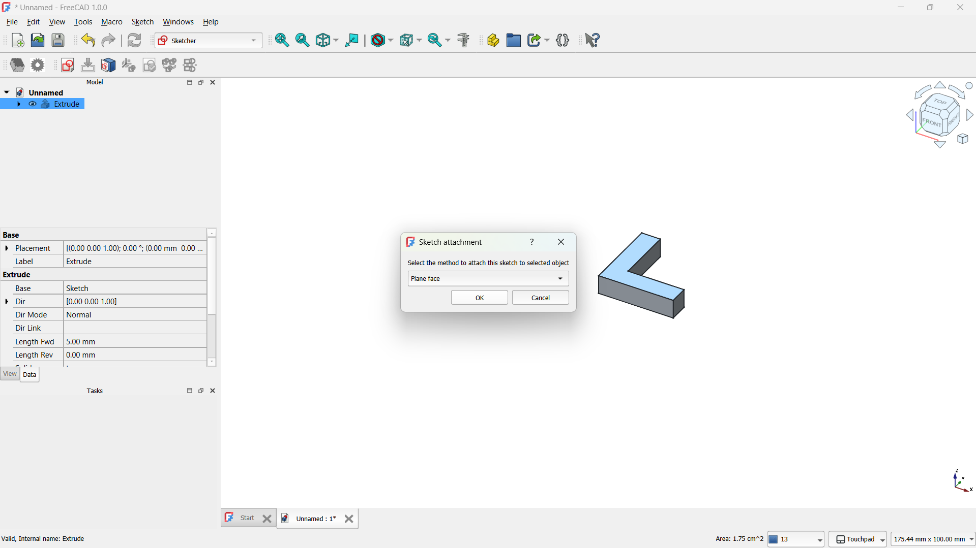
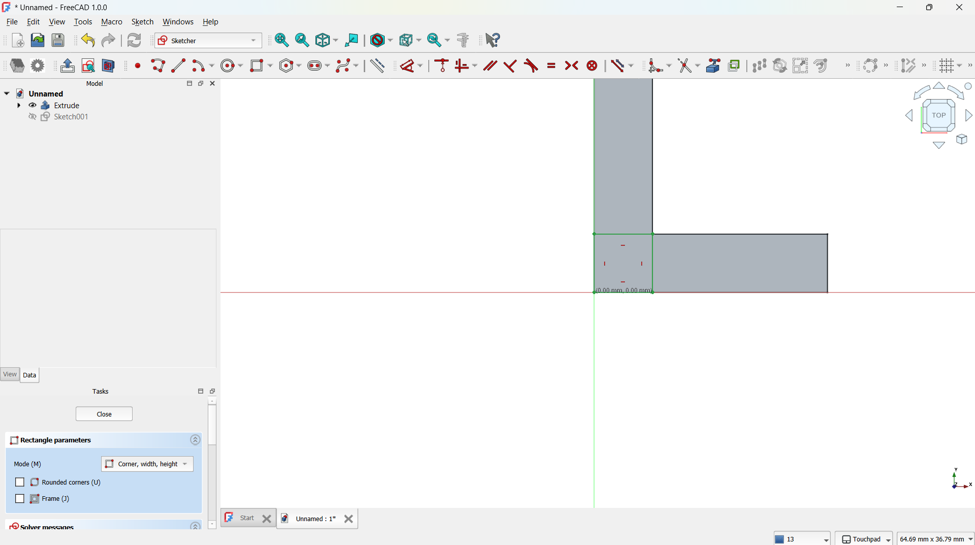
-Created a new sketch on the face of the "L".
-And made a square at the corner of the "L" to extrude into 3-point "L" using geometry tool and created the square at the corner of "L".
-Then extruded into 3 point "L".
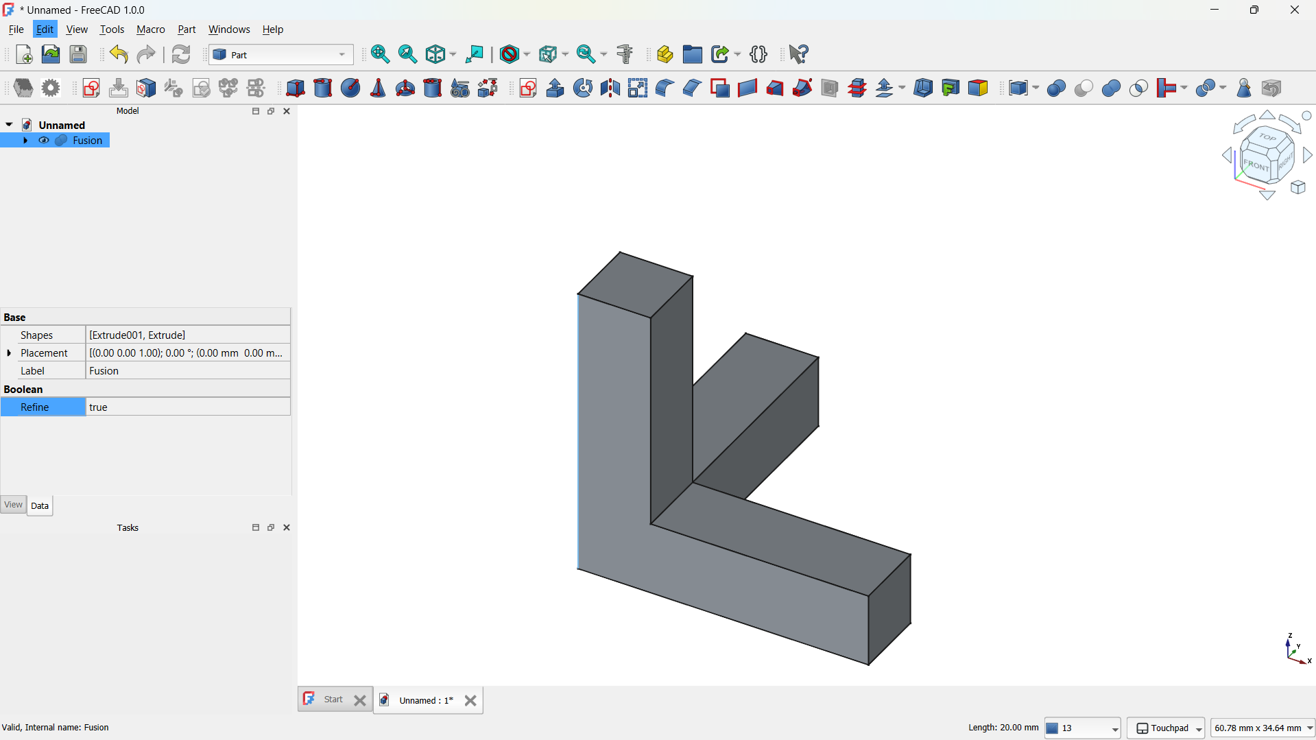
- This became the base unit of my lattice matrix.
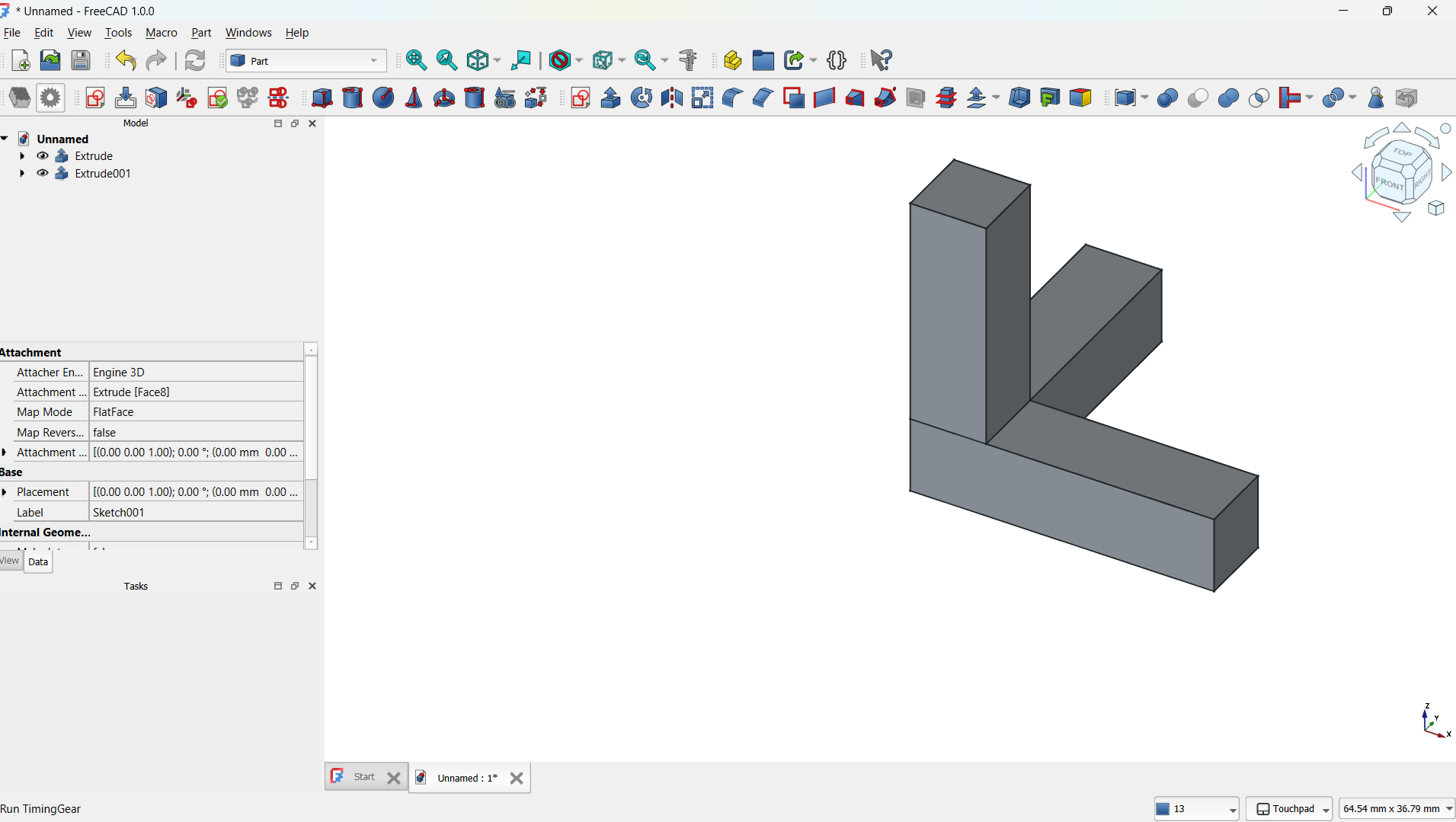
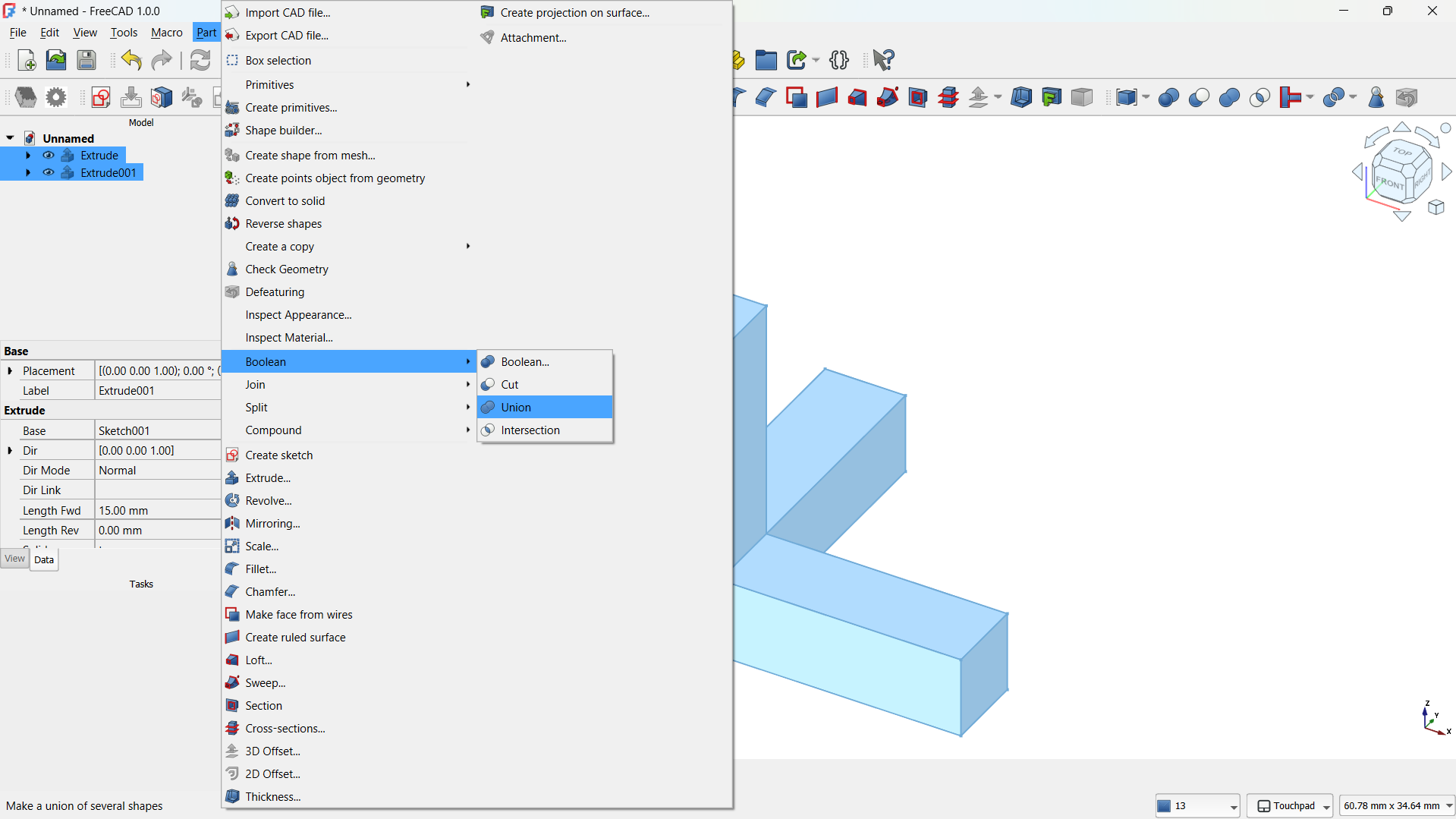
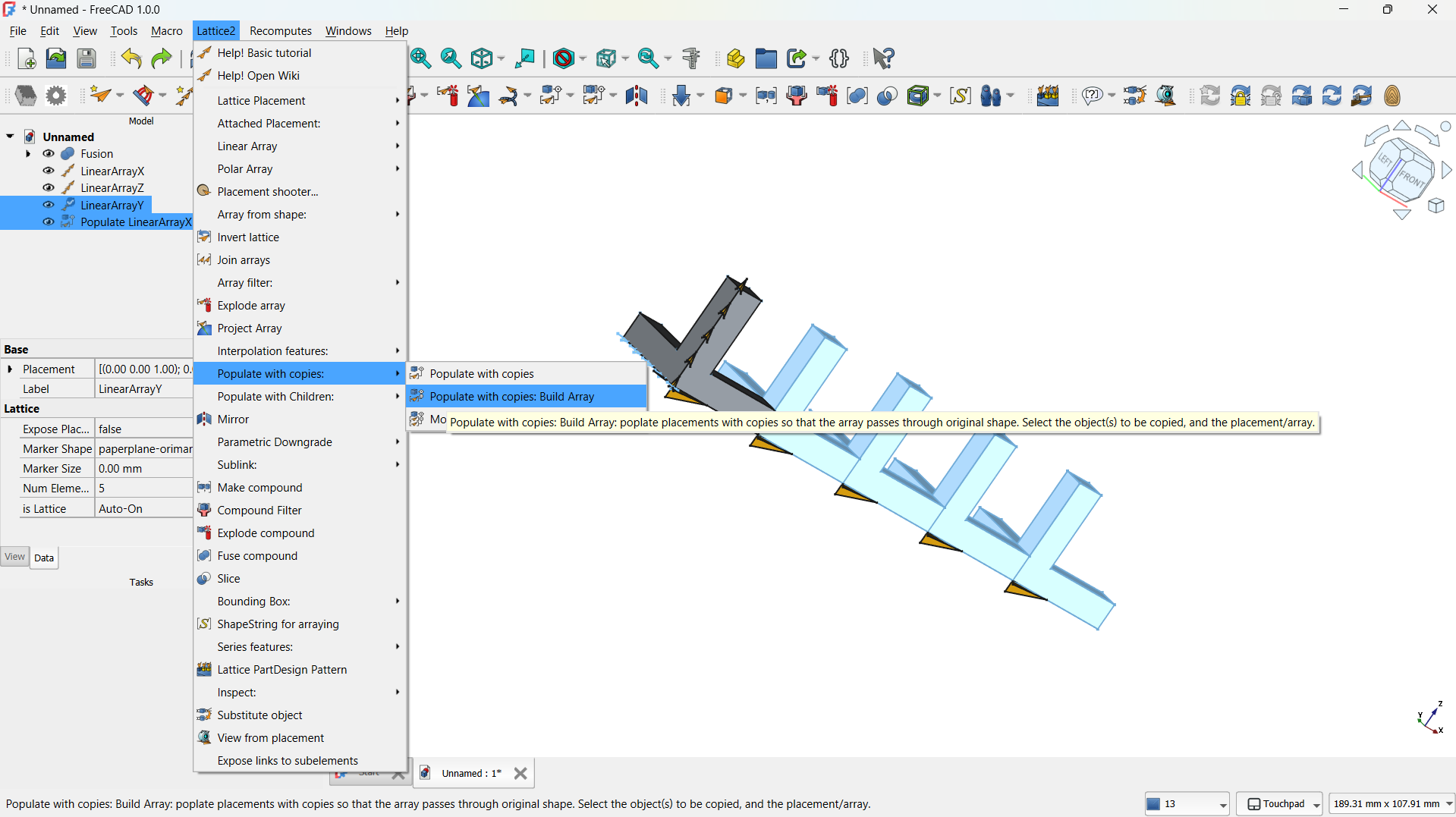
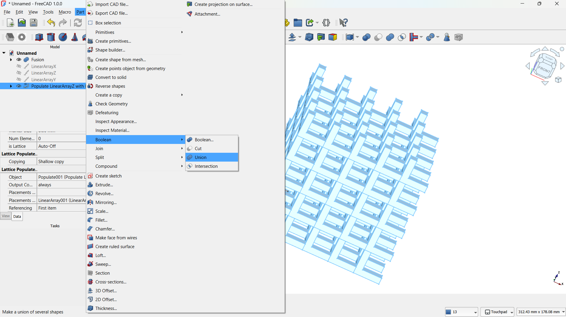
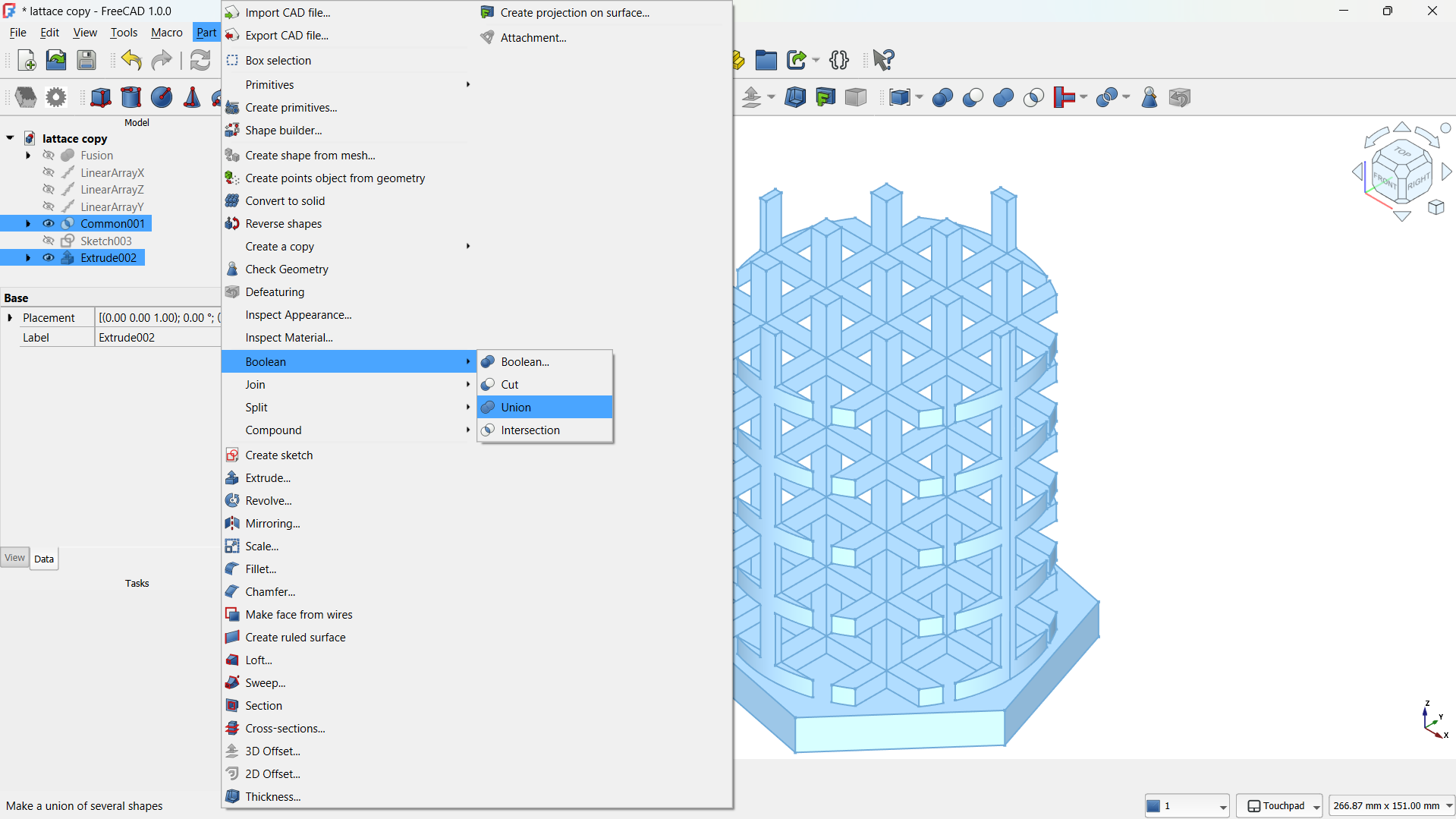
- Then joined using Part>Boolean>Union tool. - Step 3: Create a Lattice with Array Tool
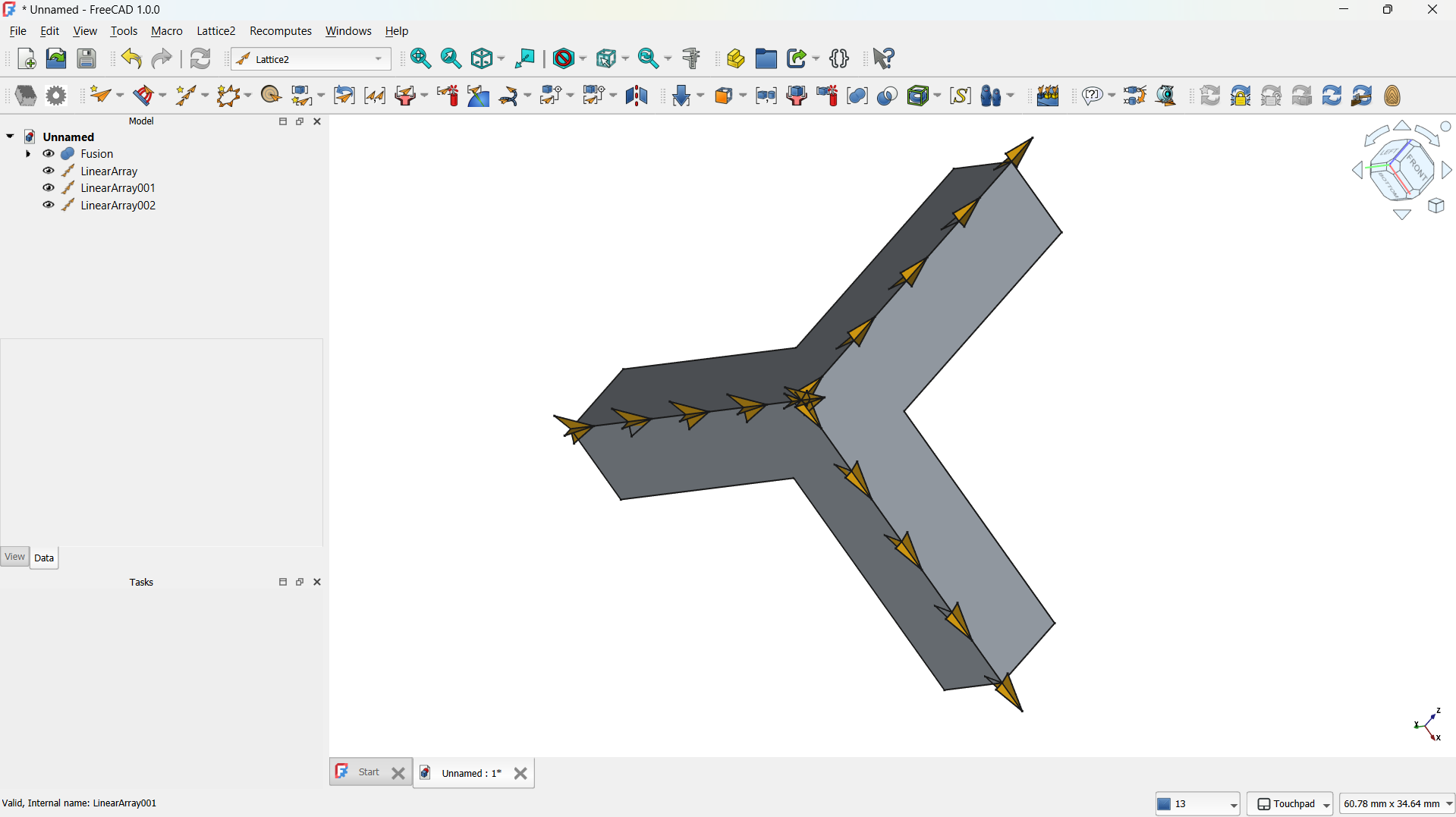
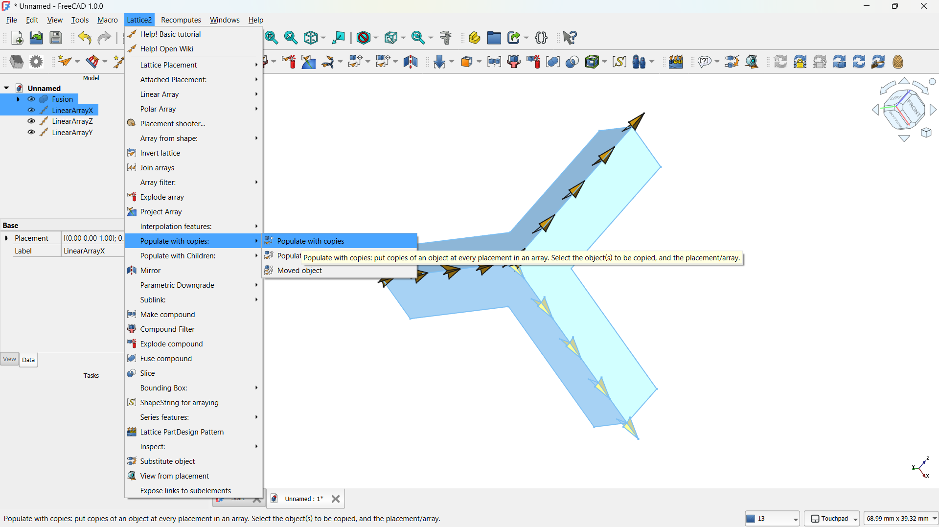
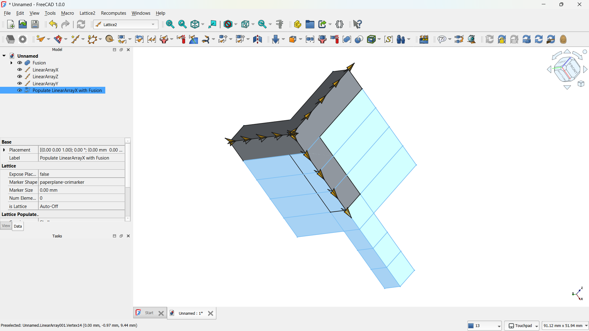
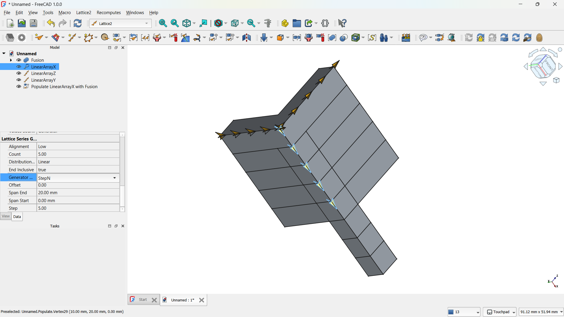
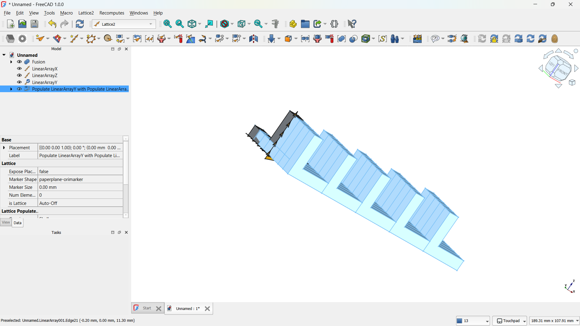
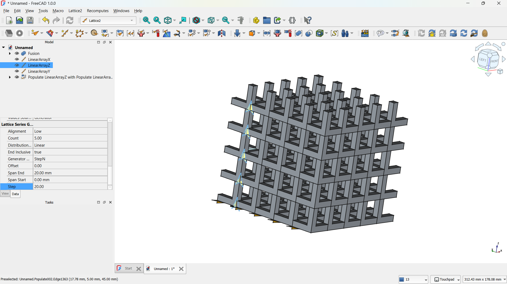
- I switched to the Lattice Workbench and selected the Array tool.
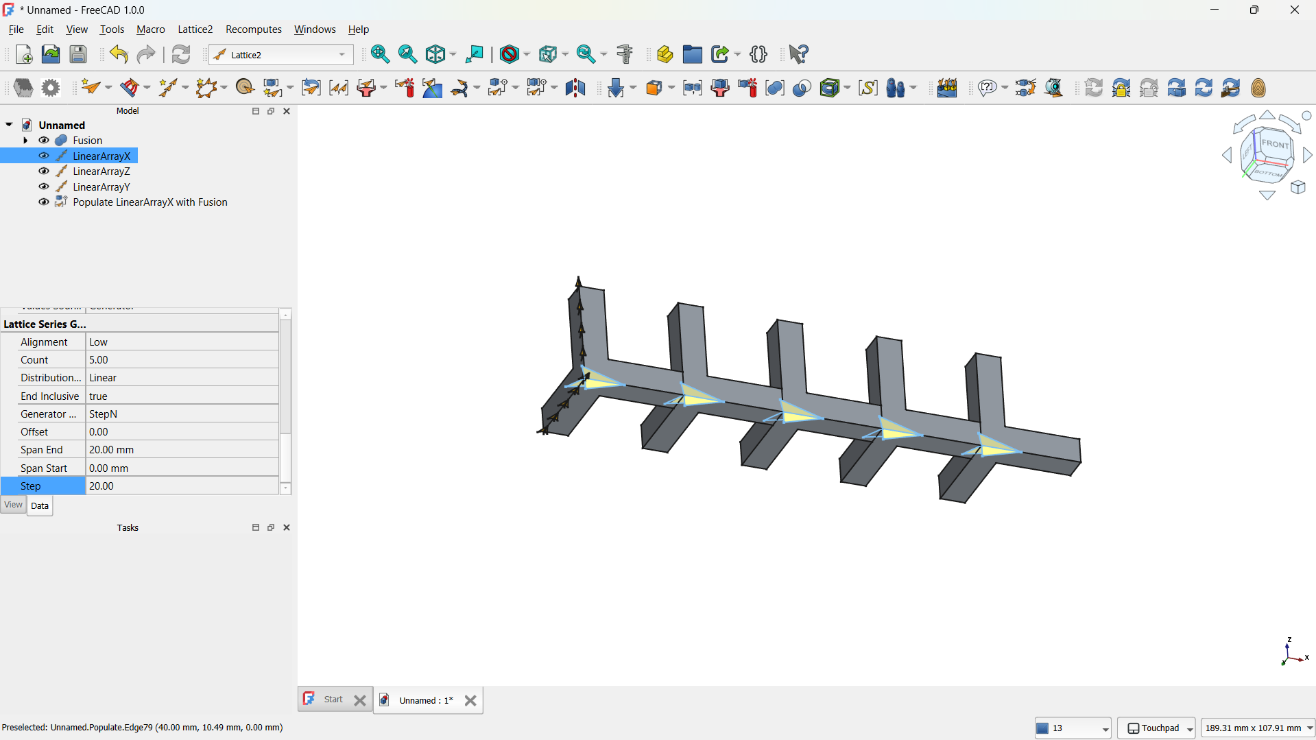
- I created a Linear Array to make direction of the copies (5) and the spacing between them (e.g., 20 mm).
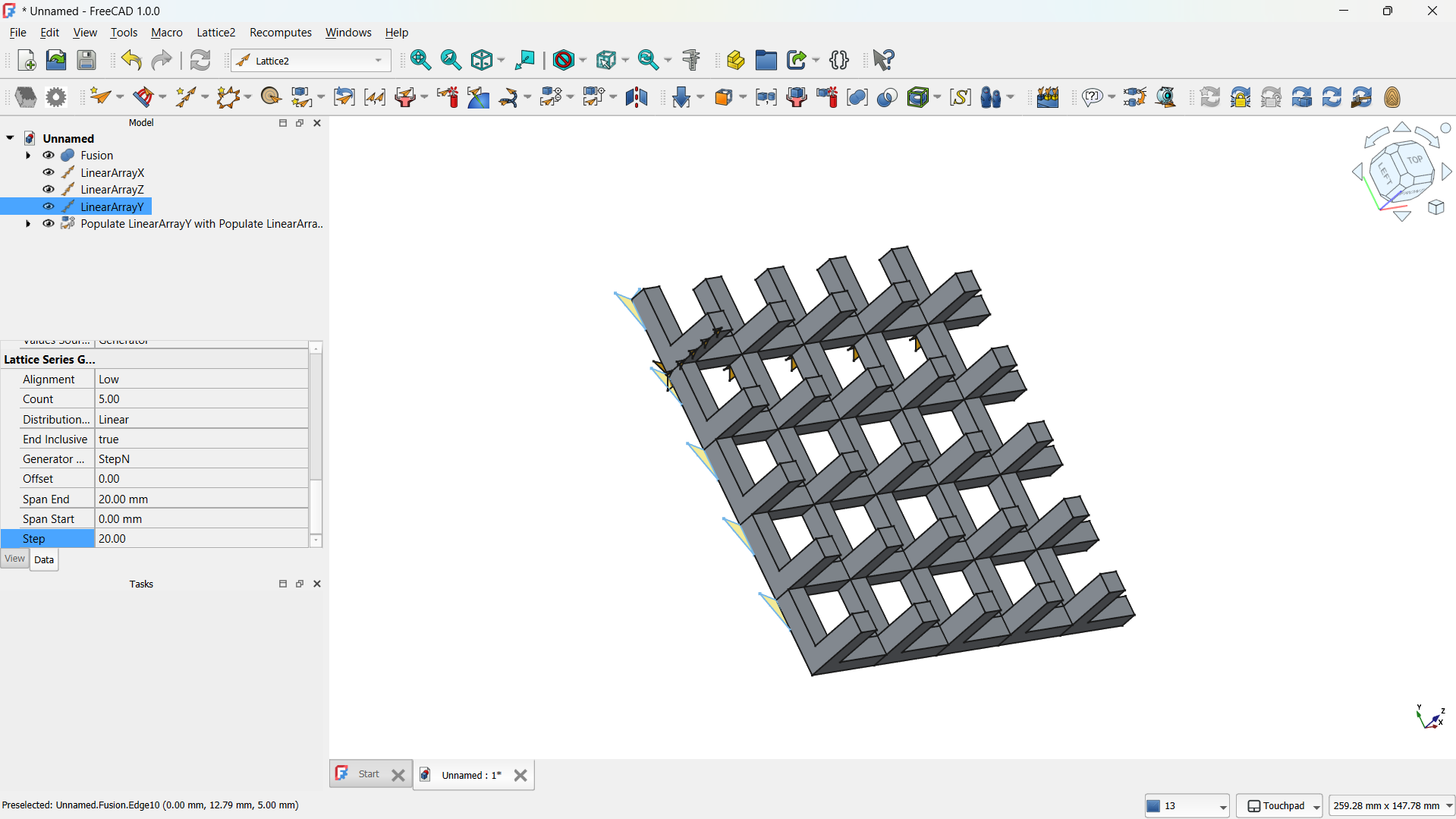
- This produced a repeating matrix of the L unit.
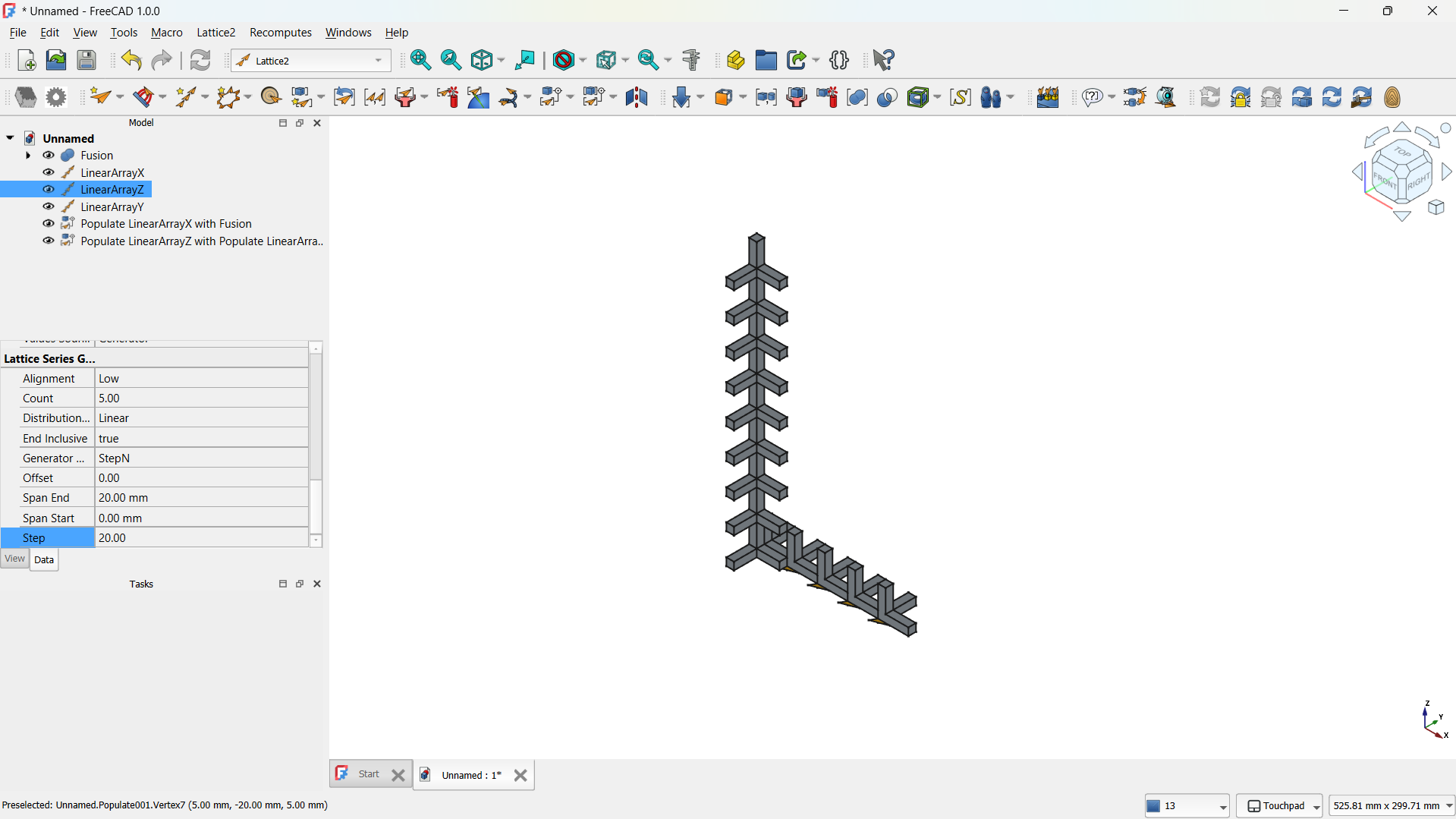
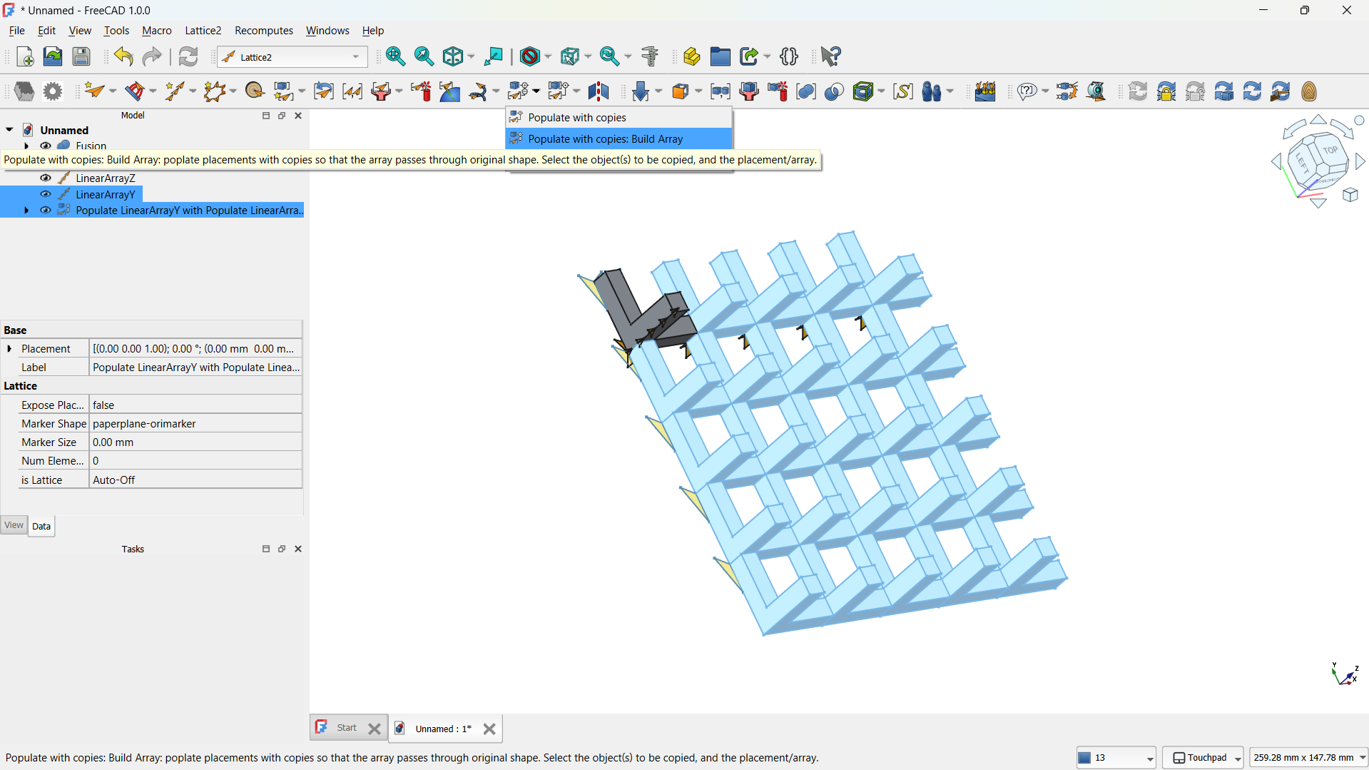
-The step repeated for both "L" shapes.
-The hole lattice joined using Boolean>Union tool. - Step 4: Adding a cylinder
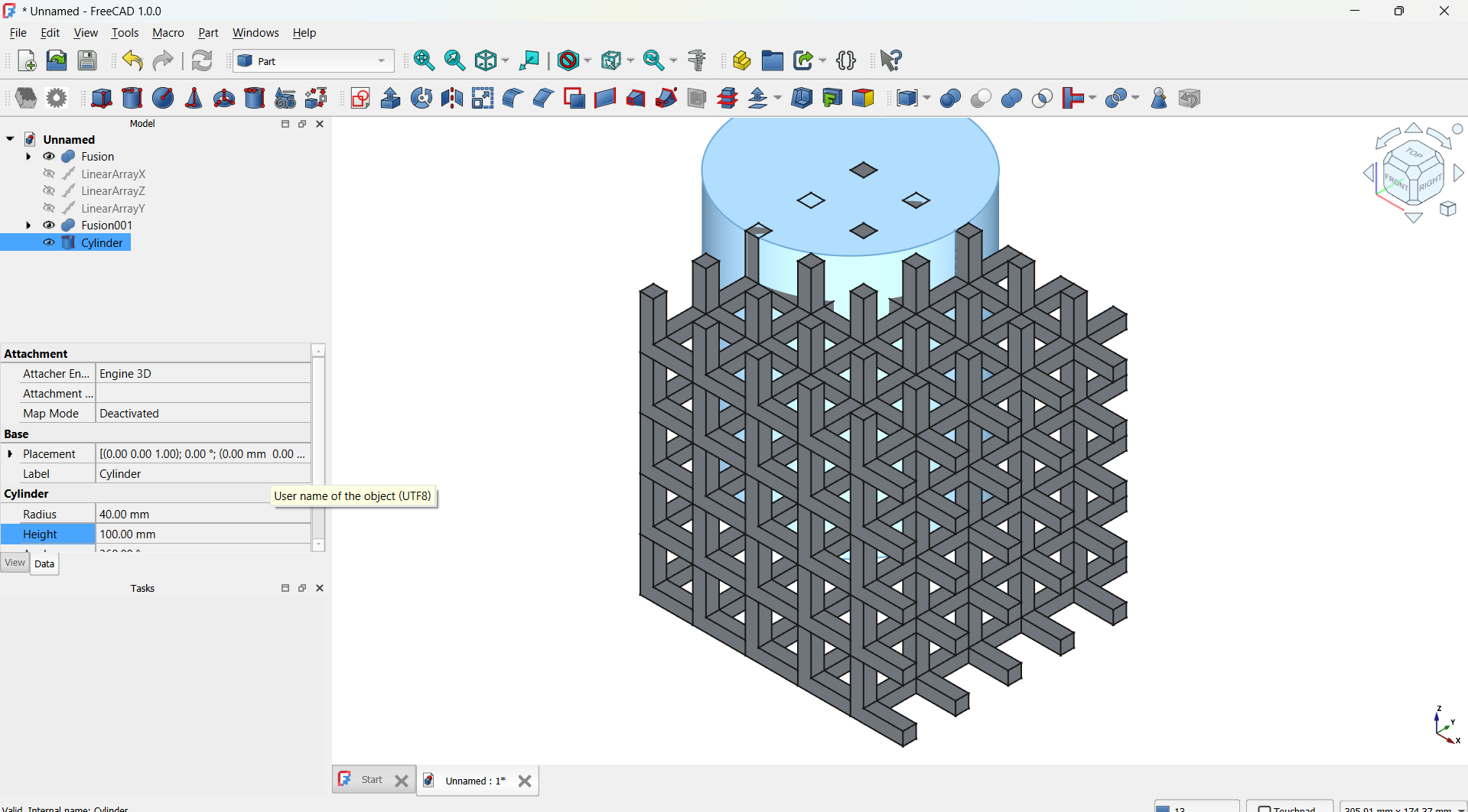
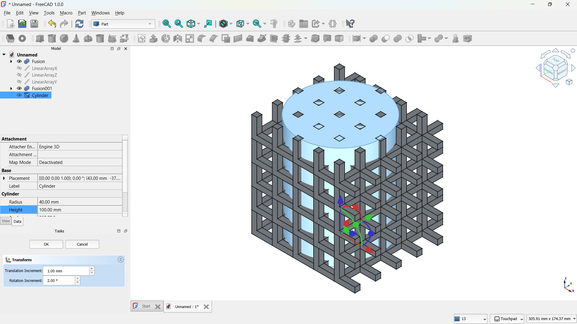
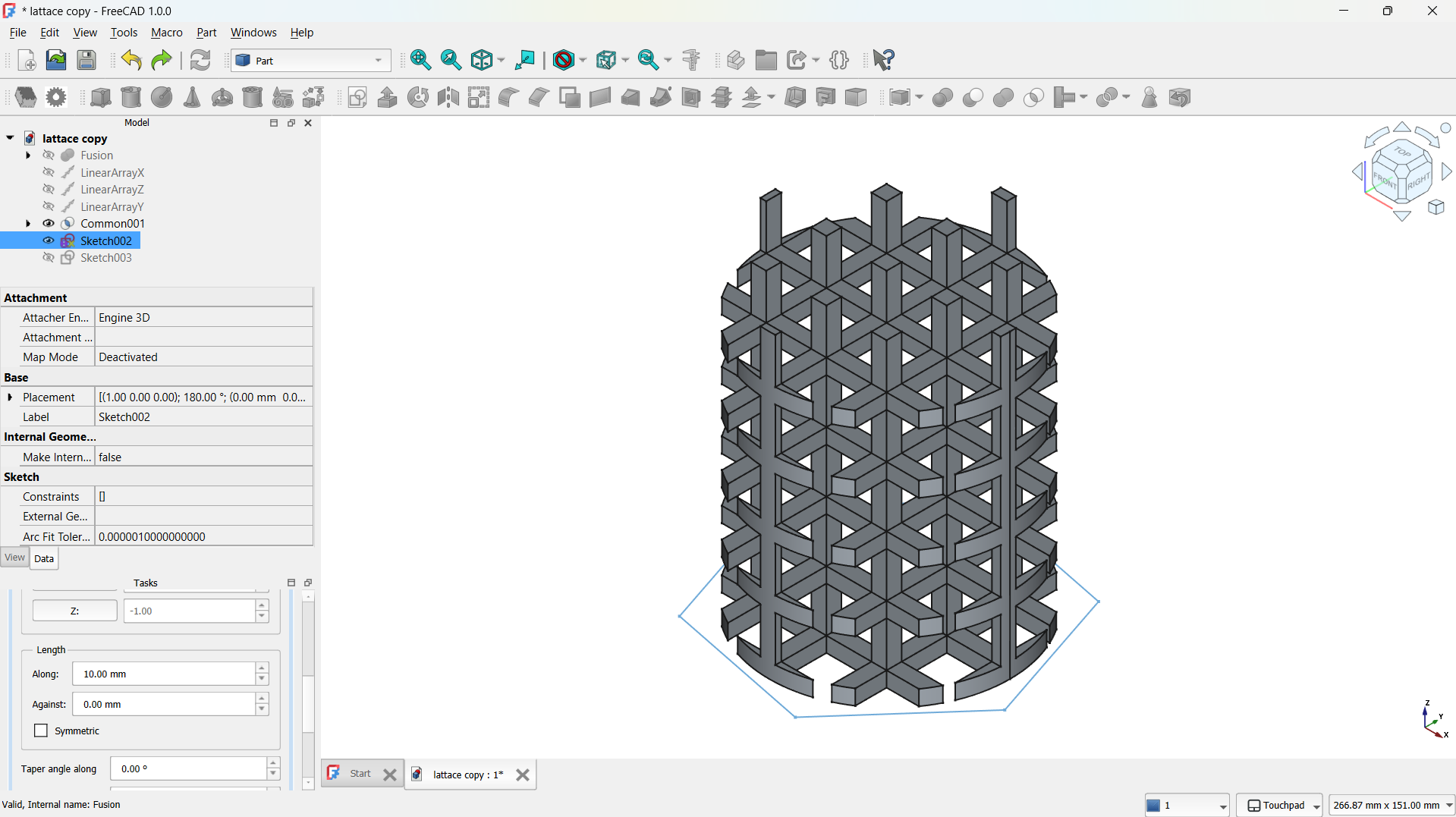
I have added a cylinder form the shapes with radius: 40mm, height: 100mm.
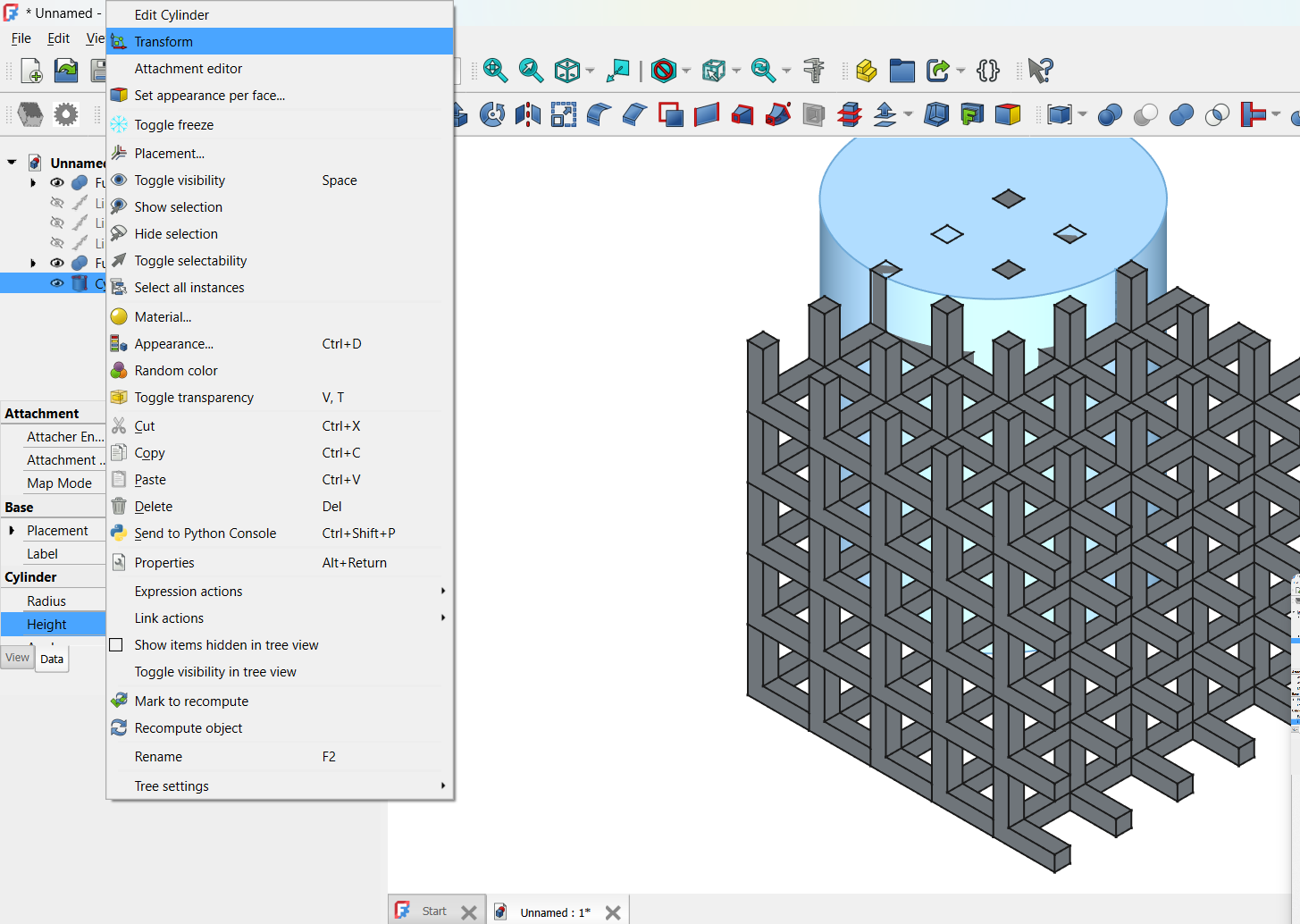
I moved the cylinder to the middle of the lattice using tranform tool, this is going to be used to shape the lattice.
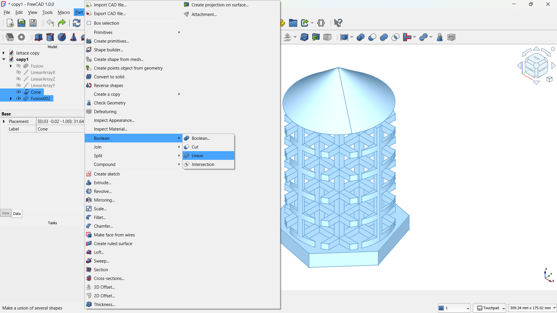
I joined them using Boolean>Union tool,
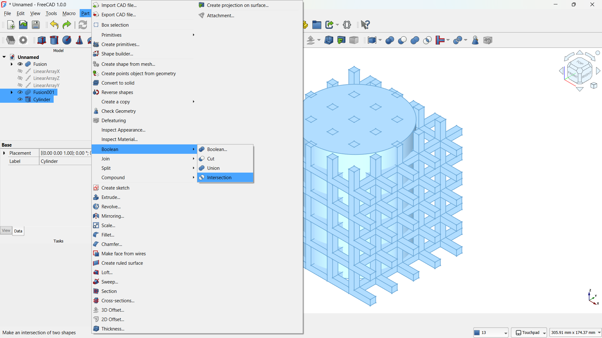
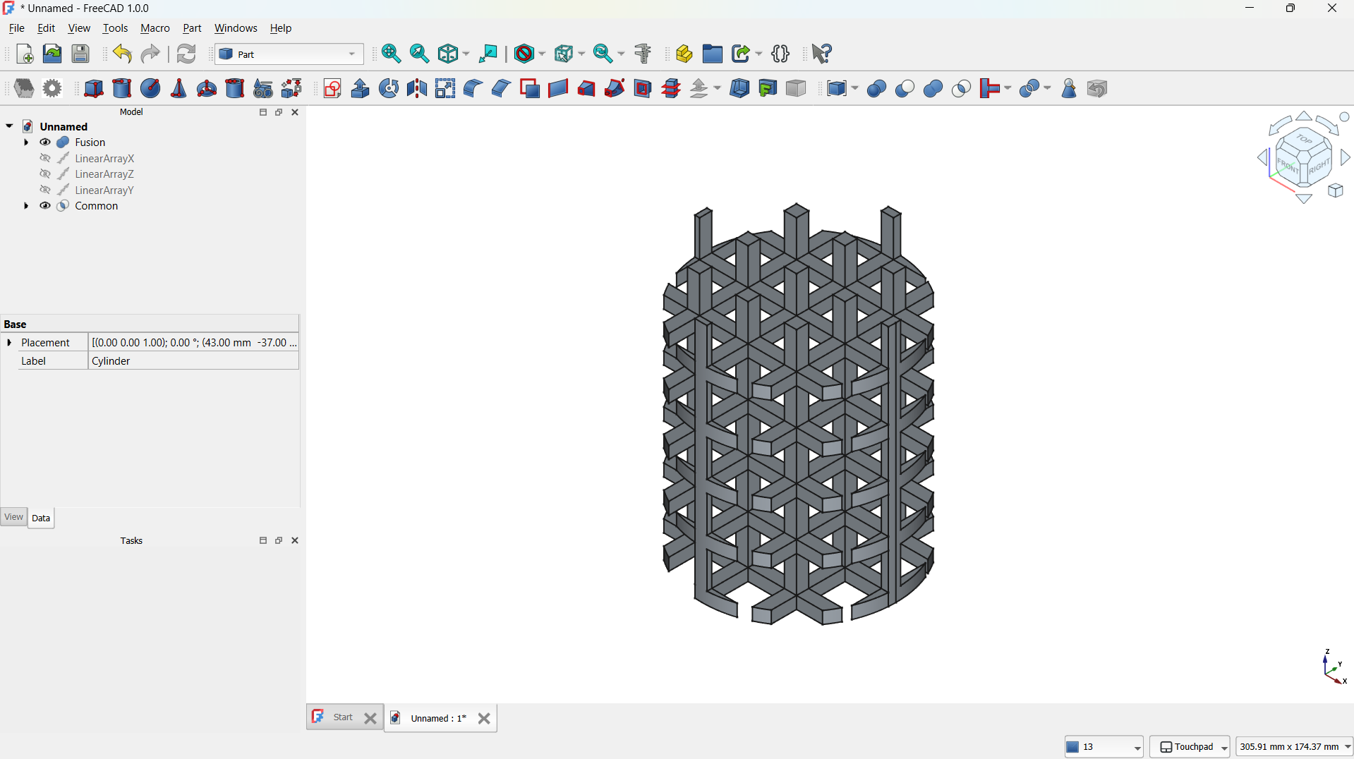
-Then shape made using Part>Boolean>Inetrsection tool. - Step 5: Adding a base
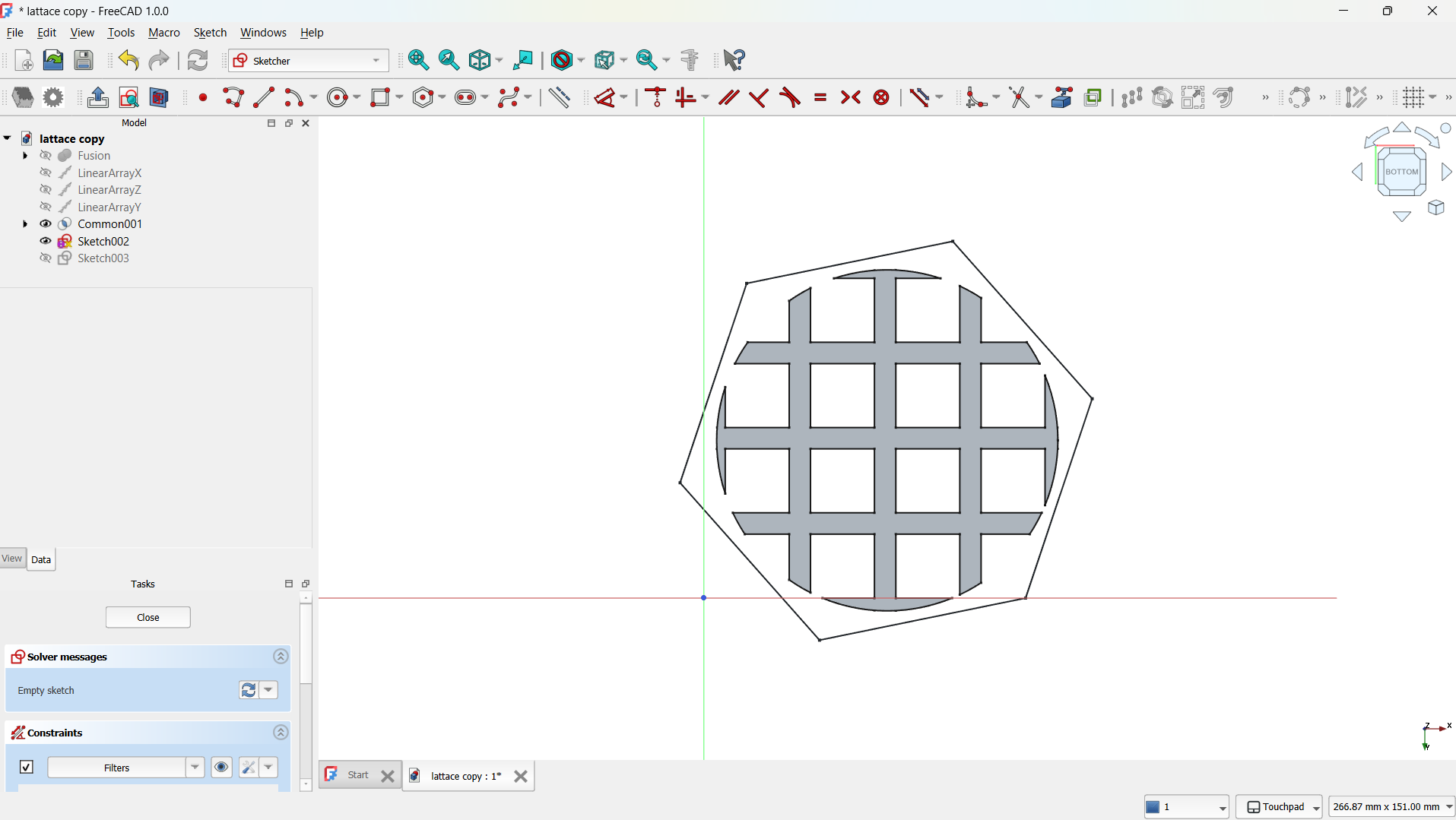
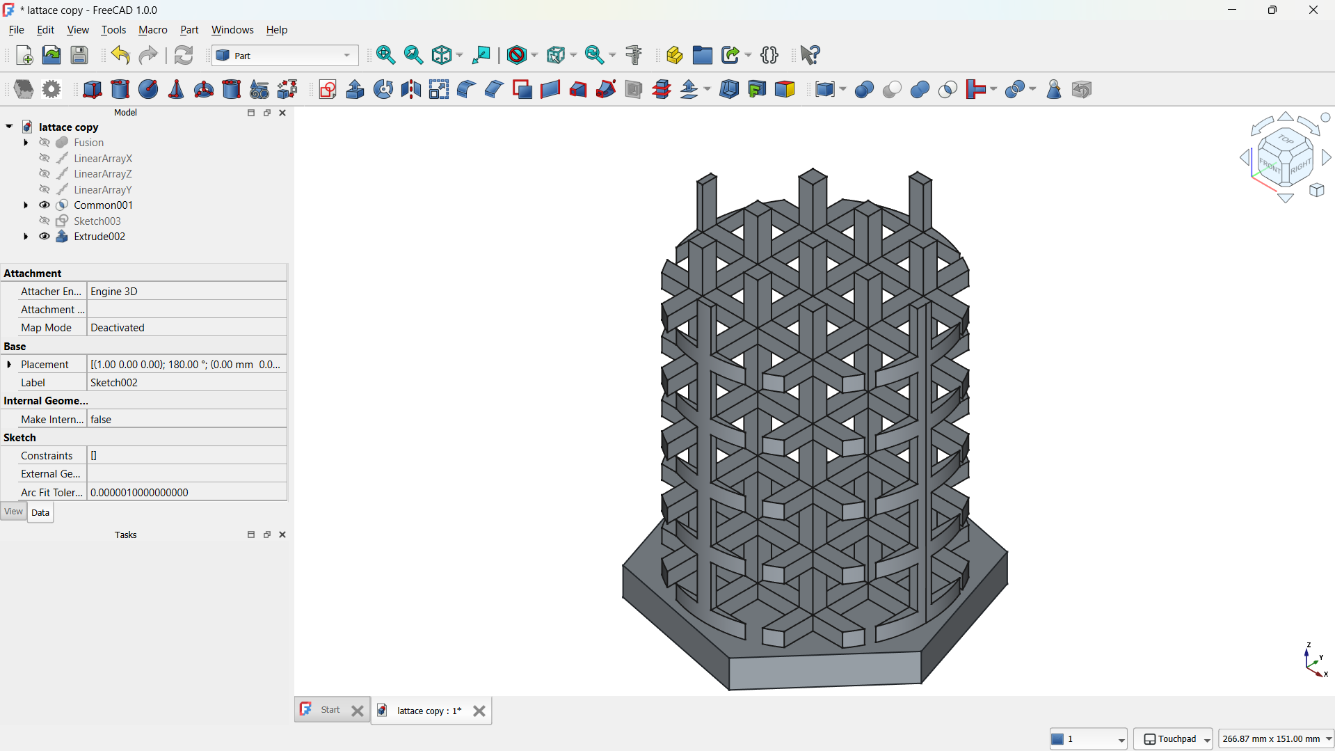
I have created sketch on the bottom plane .
Created polygone shape and extruded.
I joined them using Boolean>Union tool,
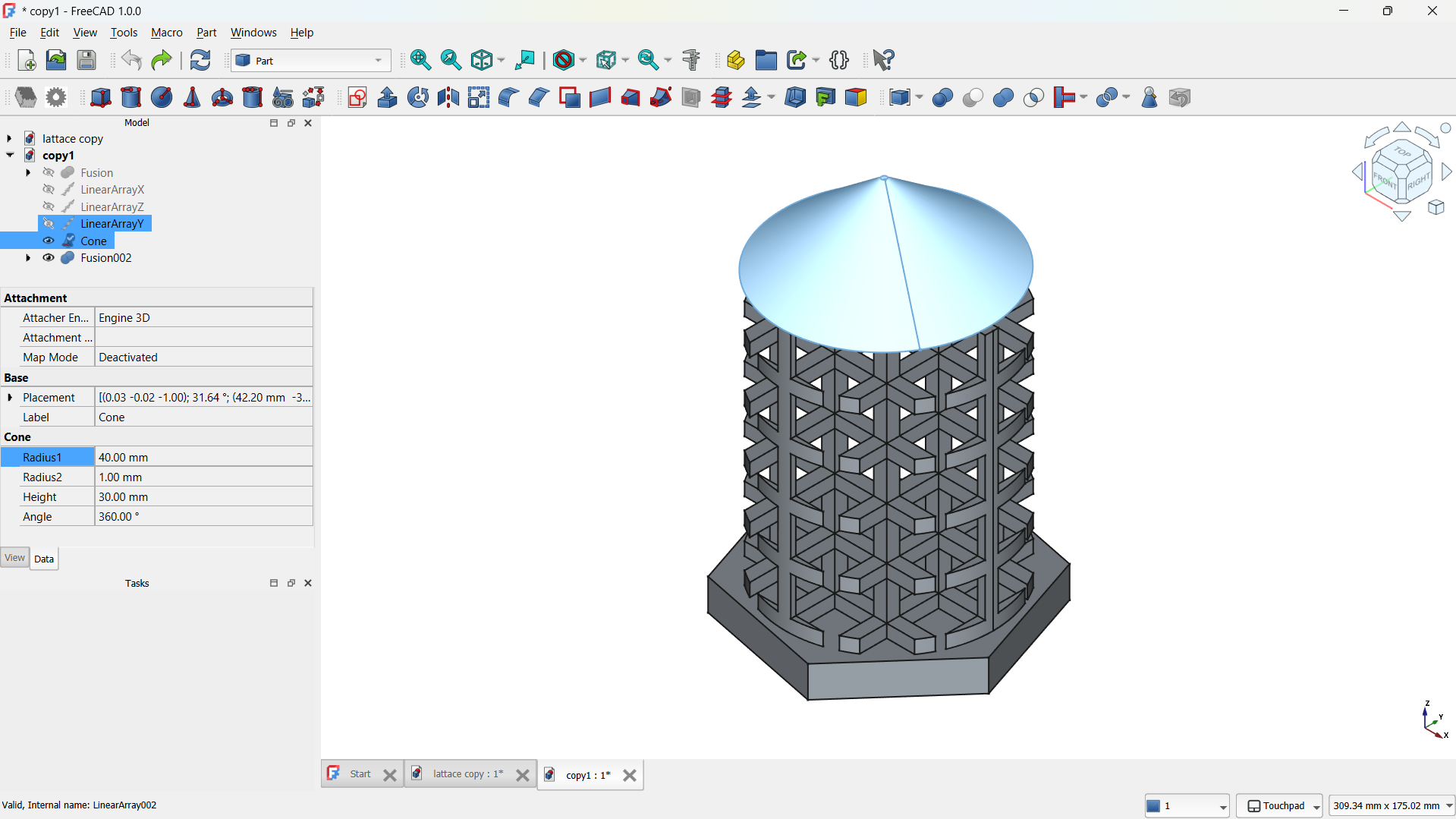
-Then shape made using Part>Boolean>Inetrsection tool. - Step 6: Adding cone
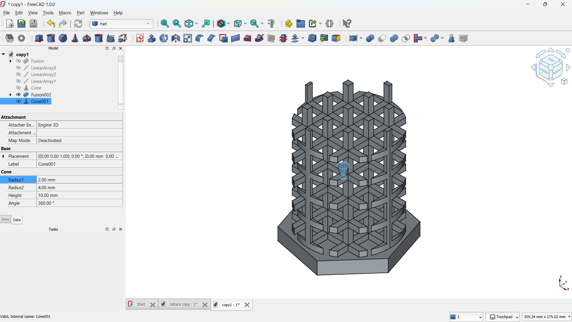
I have adde a cone form the shapes with radius: 1mm, Second radius: 40mm. I moved the cone on top of the lattice using tranform tool, this is going to be used to shape the lattice.
I joined them using Boolean>Union tool. - Select the body or object in the model tree
- Go to File > Export
- Select STL Mesh (*.stl) and save it to a directory
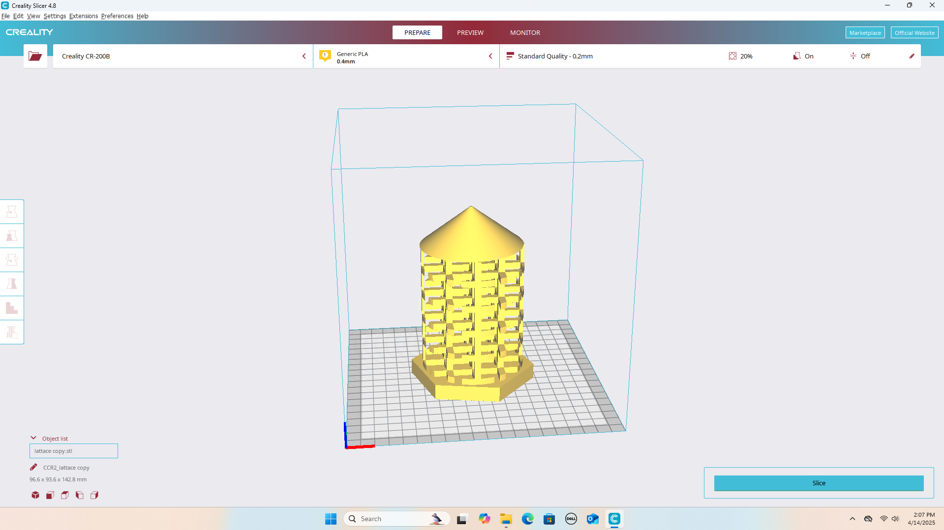
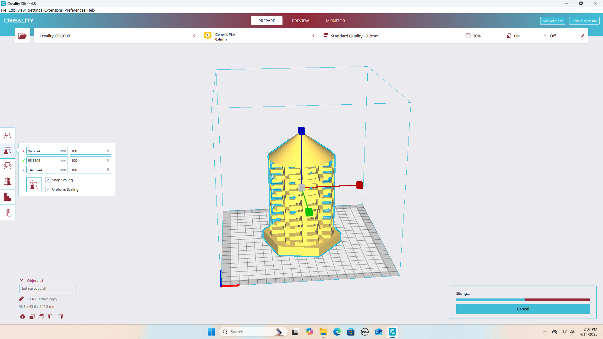
- Imported the STL file into the slicer workspace
- Used the Scale tool to resize the model to fit the print bed.
- Used Move and Rotate tools to position the object flat on the print surface
- Clicked Slice to generate G-code
- The G-code save and ready for 3D print.
- After slicing the gcode send to the 3D printer using USB.
- The model is selected form the printer interface the start printing.
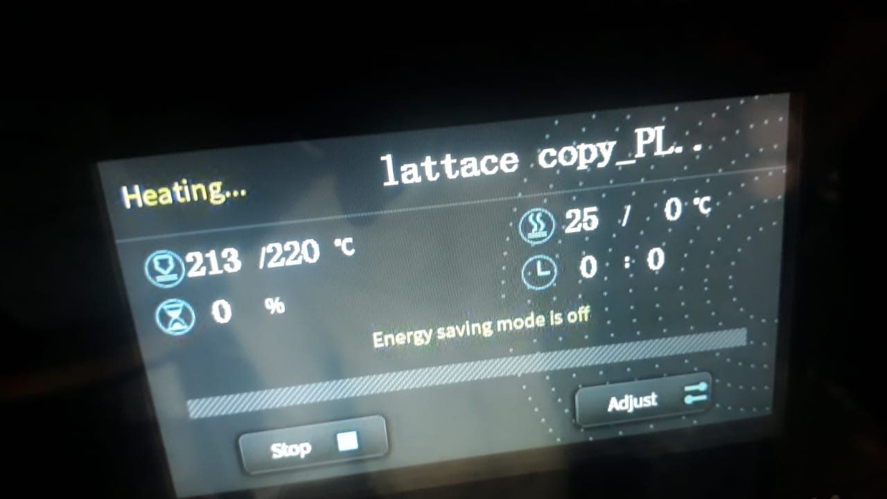
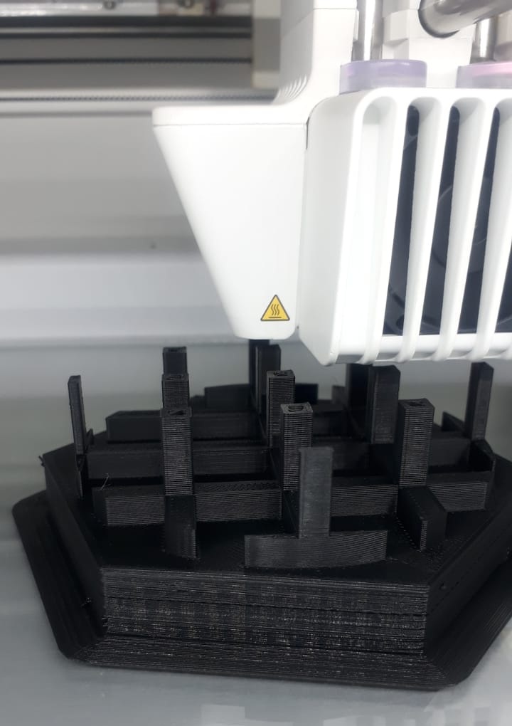
- The printer speed adjusted to 40 for better quality, and nozzle temperature to 220.
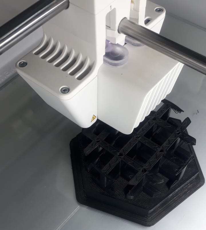
- The printer preheat before starting
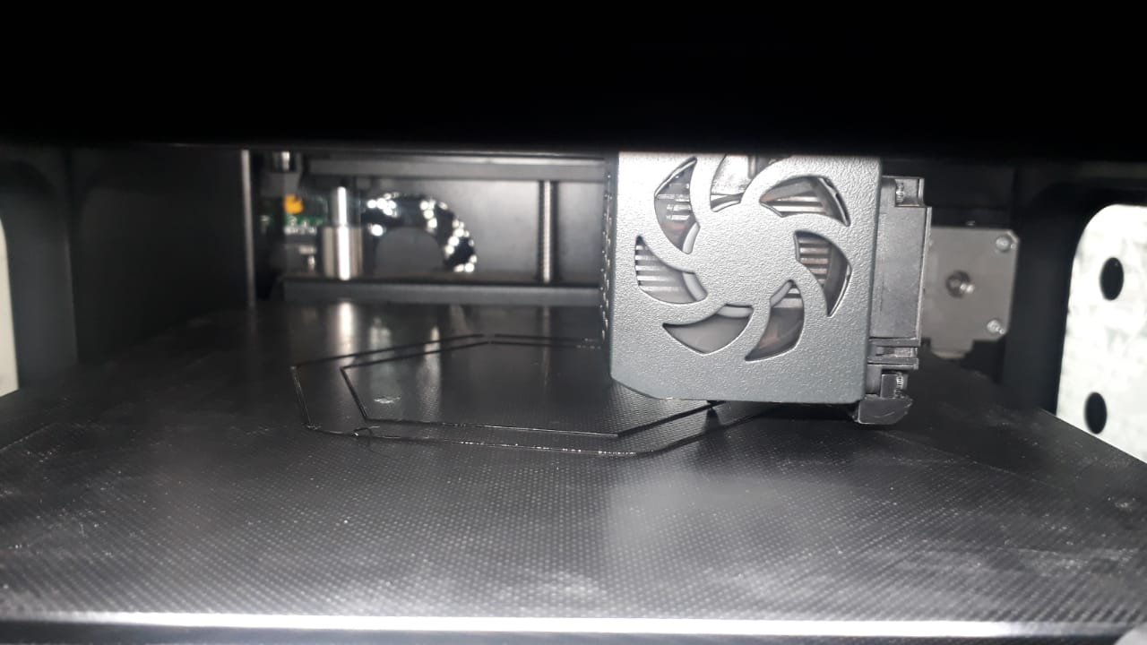
- Printing started
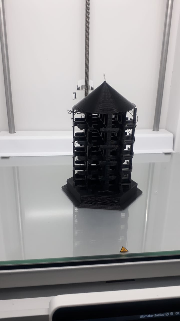
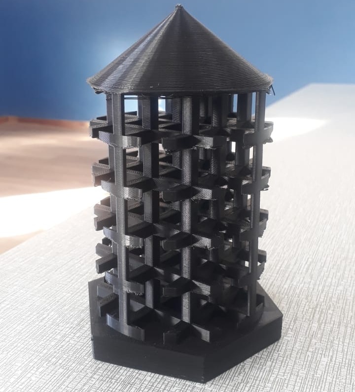
- Final product
- Download from the Creality Download Center.
- Install CR Studio (look for the version compatible with CR-Scan 01).
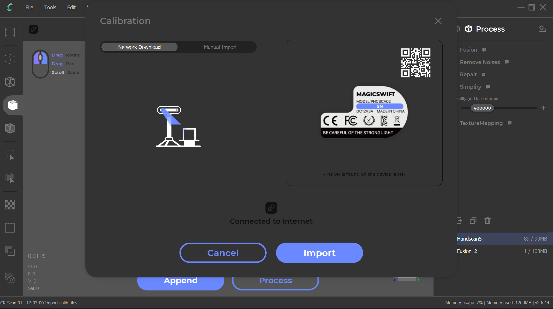
- Connect the scanner to your PC via the USB cable and power adapter.
- Launch CR Studio.
- If prompted, perform camera calibration or background calibration (helps with tracking).
- Choose Handheld or Turntable mode.
- Place object at center of turntable.
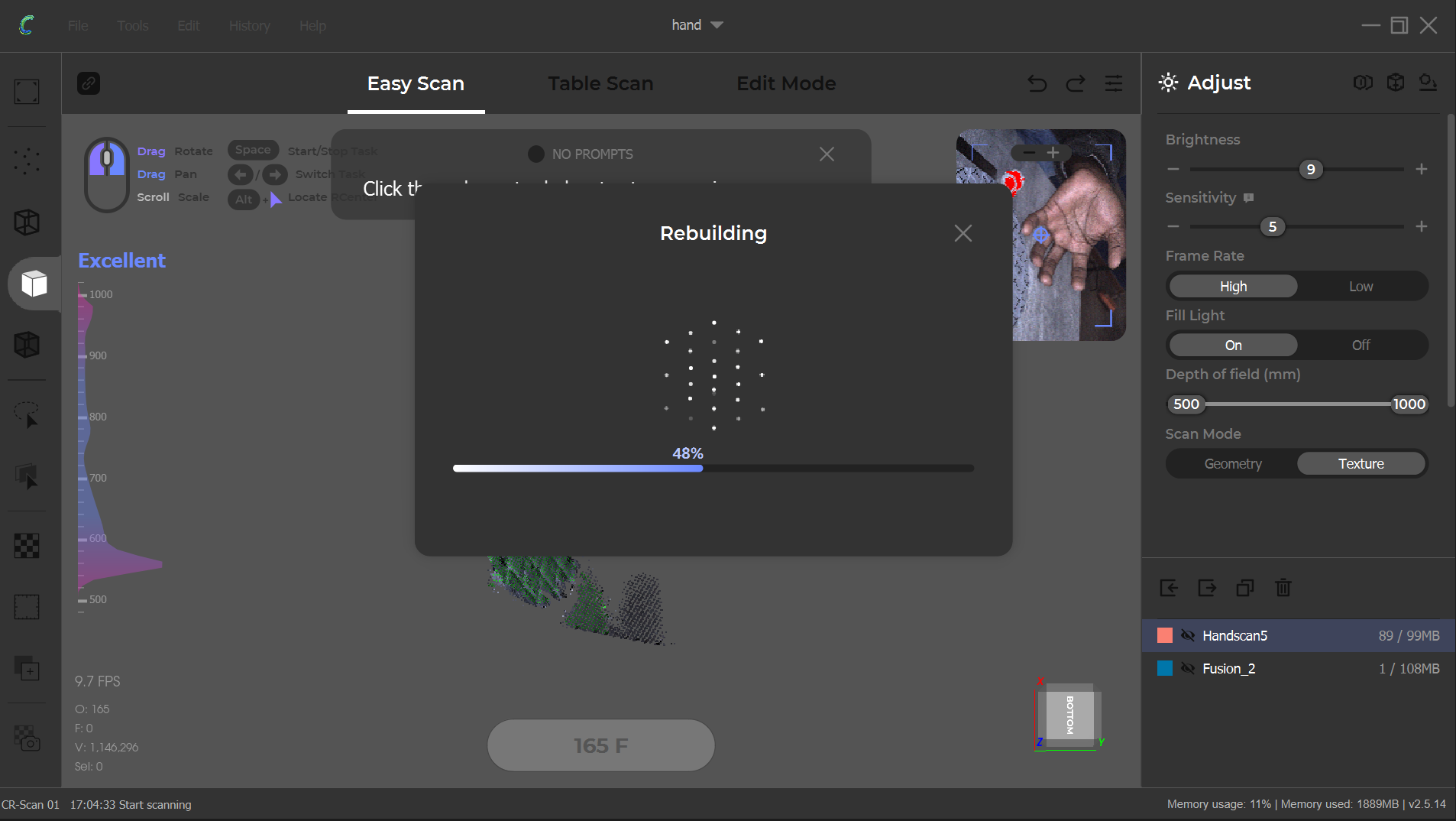
- Select “Turntable Mode” and choose “Geometry Scan” or “Texture Scan”.
- Scanner will automatically capture as the turntable rotates.
- Ensure object is stable and lighting is consistent.
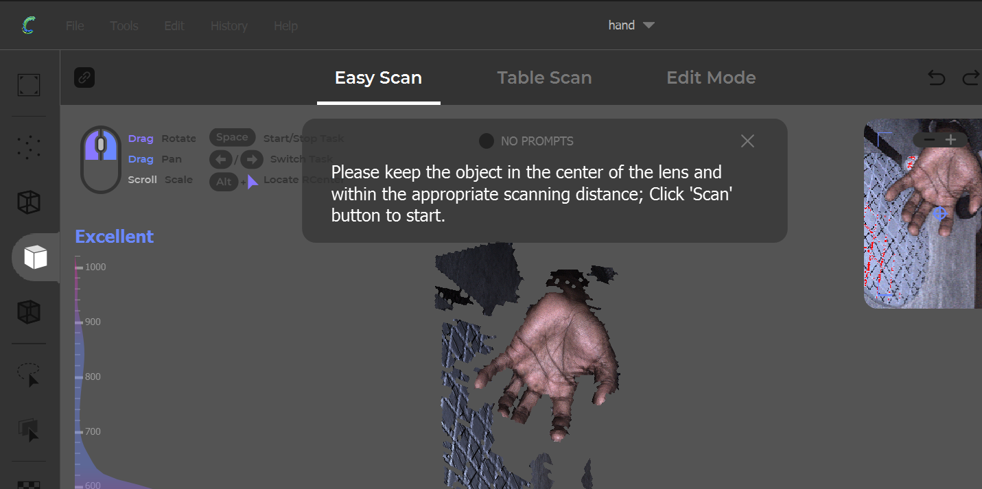
- Hold scanner 30–40cm from the object.
- Move slowly around it (360° if possible).
- Trackers in CR Studio help guide your movement.
- You can pause/resume the scan.
- Noise Reduction
- Hole Filling
- Mesh Simplification
- Clean up overlapping or floating geometry
- Export your final model as
- .STL for 3D printing
- .OBJ or .PLY for color/textured models
- Use slicing software (e.g., Creality Slicer, Cura) if printing.
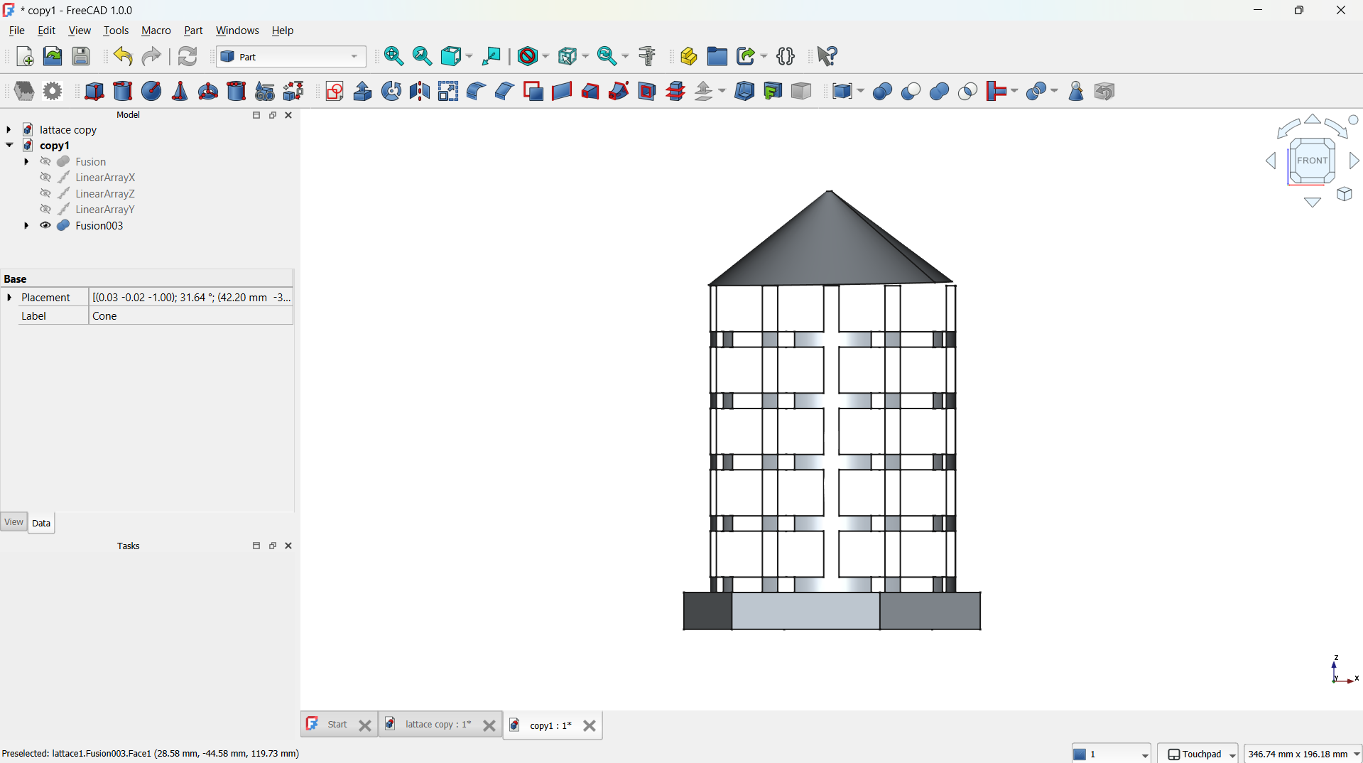
Front view.
Exporting the Model for 3D Printing
Once the design was finalized, I exported it as an STL file for 3D printing:
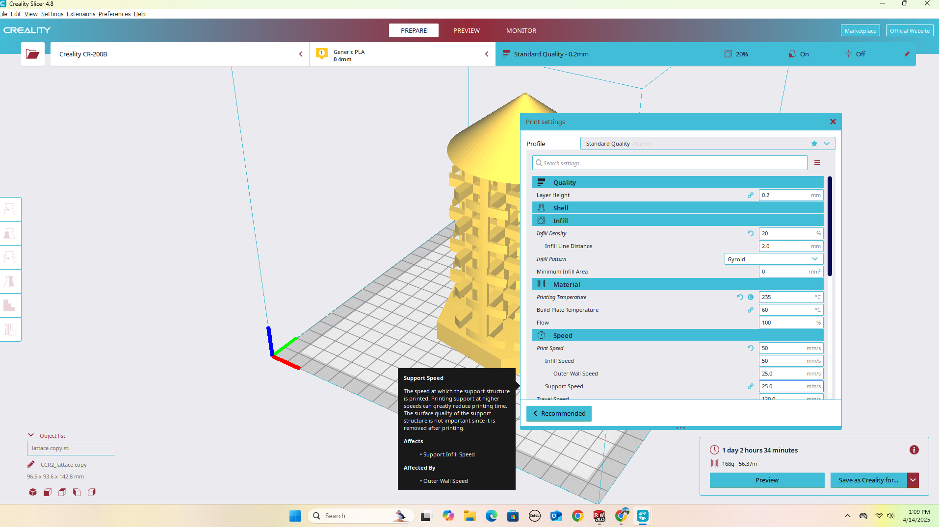
Slicing the STL for 3D Printing
I imported the STL file into Creality Print software to prepare it for 3D printing.
3D printing
The final product removed from the print the removed small floating filament at the edges.
How to 3D Scan with CR-Scan 01`
1. Install CR Studio
Once you stop scanning, use the following tools:
Design files
3D Scan
Gcode Slice file for 3D
Design file for FreeCAD