Embedded System programming
In this page I covered the embedded system programming, This is where the link to the group assignment is found.
Group assignment:
Demonstrate and compare the toolchains and development workflows for available embedded architectures
Document your work to the group work page and reflect on your individual page what you learned
In this group work I have learned different types of micro-controller and how their applications. Through their datasheet I have learned how to program and the different languages used in micro-controllers. Also learned different Integrated Development Environment (Thonny, Arduino IDE)
The link to the group assignment Group assignment
Individual assignment:
Browse through the datasheet for your microcontroller
Write a program for a microcontroller, and simulate its operation, to interact (with local input &/or output devices) and communicate (with remote wired or wireless connection).
In this project I have chosen Raspberry Pi Pico because it is readily available in the lab for test and learning the concept.
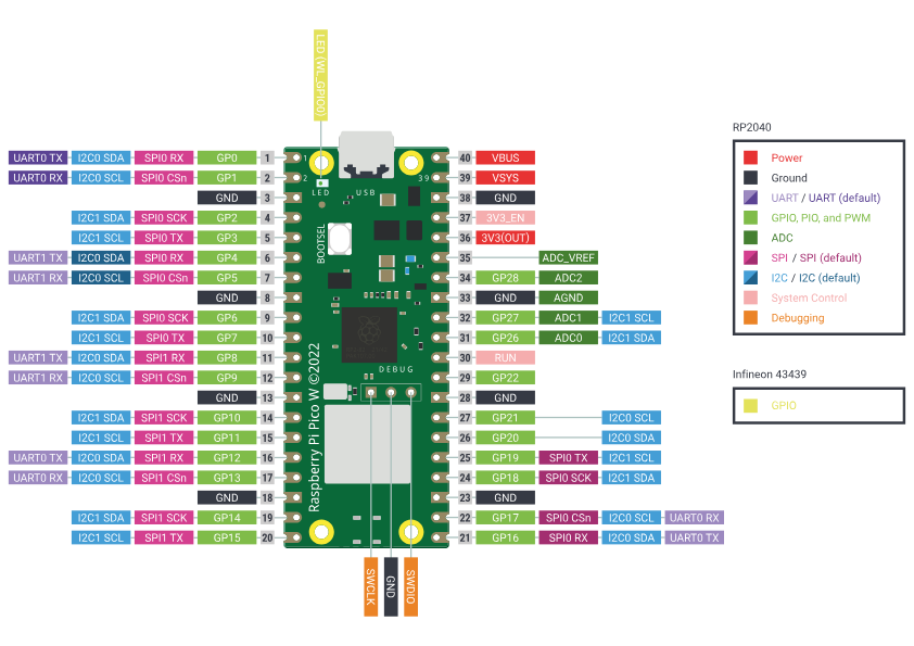
Pi Pico datasheet
The Raspberry Pi Pico is a low-cost, flexible development board built on the RP2040 microcontroller. Below are its key features:
Board Features
- Microcontroller with 2MB Flash
- Micro-USB B port for power, data, and reprogramming Flash
- 40-pin 21×51 'DIP' style 1mm PCB with 0.1" through-hole pins and edge castellations
- 26 multifunction 3.3V GPIOs (23 digital-only, 3 ADC capable)
- Can be surface-mounted as a module
- 3-pin ARM Serial Wire Debug (SWD) port
- Flexible power supply architecture (USB, external, battery)
- High quality, low cost, and widely available
- Comprehensive SDK, examples, and documentation
Microcontroller Highlights
- Dual-core Cortex-M0+ processor up to 133MHz
- On-chip PLL for variable core frequency
- 264kB multi-bank high-performance SRAM
- External Quad-SPI Flash with XIP and 16kB on-chip cache
- On-board USB 1.1 (host or device)
- 30 multifunction GPIOs (4 ADC-capable)
- 1.8-3.3V I/O (Pico I/O fixed at 3.3V)
- 12-bit 500ksps ADC
- Digital peripherals:
- 2 × UART
- 2 × I2C
- 2 × SPI
- 16 × PWM channels
- 1 × Timer with 4 alarms
- 1 × Real Time Counter
- 2 × Programmable IO (PIO) blocks with 8 state machines total
- Flexible high-speed user-programmable IO (can emulate SD, VGA, etc.)
Additional Design Details
- On-board components: Flash (Winbond W25Q16JV), crystal (Abracon ABM8-272-T3)
- Power supply components and USB connector integrated
- Most RP2040 pins exposed on board edges for user I/O
- 4 RP2040 IOs used for internal functions (LED, SMPS control, voltage sensing)
- Supports soldered 0.1" headers or surface mounting (castellated pins)
- SMT pads under USB connector and BOOTSEL button for reflow soldering access
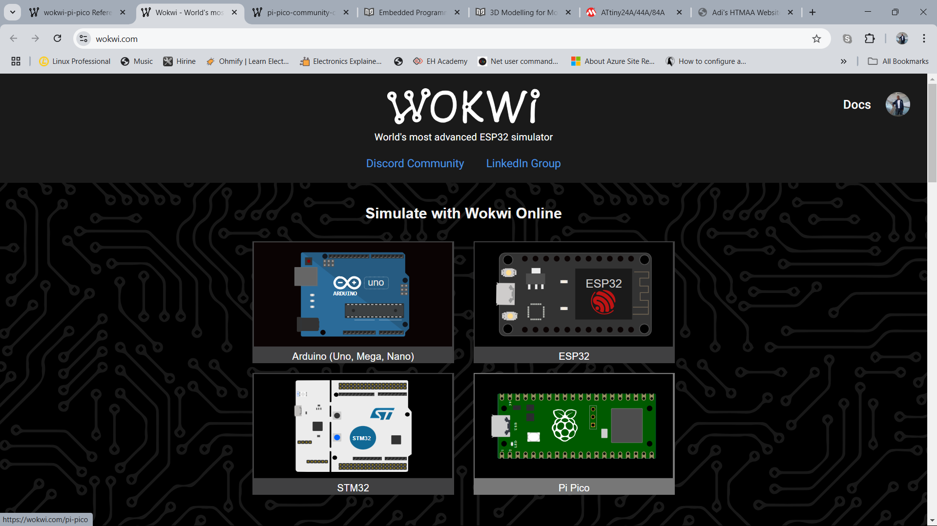
To continue with this project I firstly browsed the Wikwi website, then signed-up to create an account.
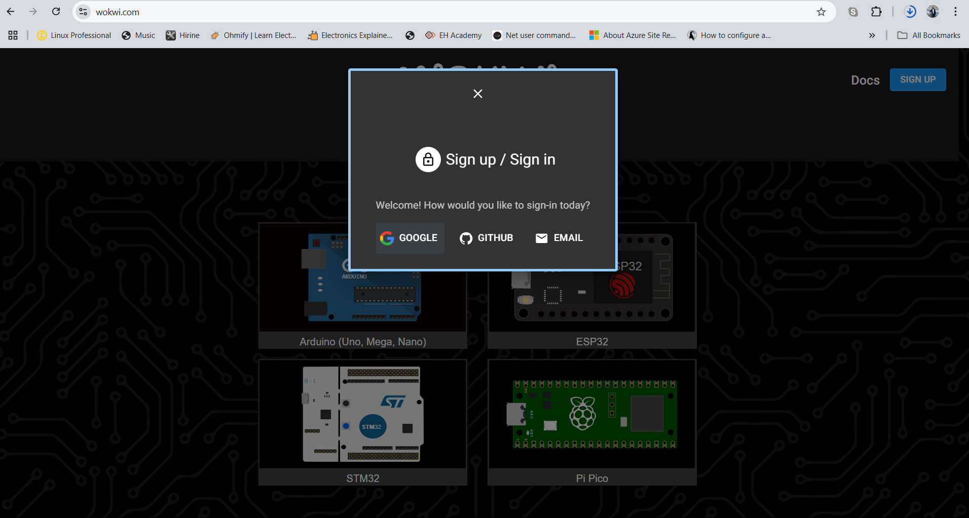
After signing up, I selected Pi pico to create a project on Raspbbery Pi controller.
I selected blinking light and added more components to customize the project and the code.
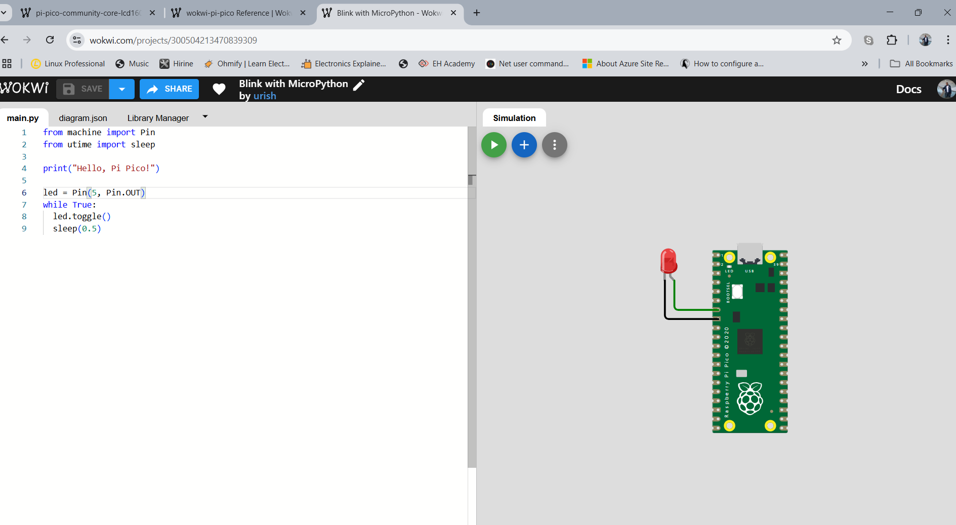
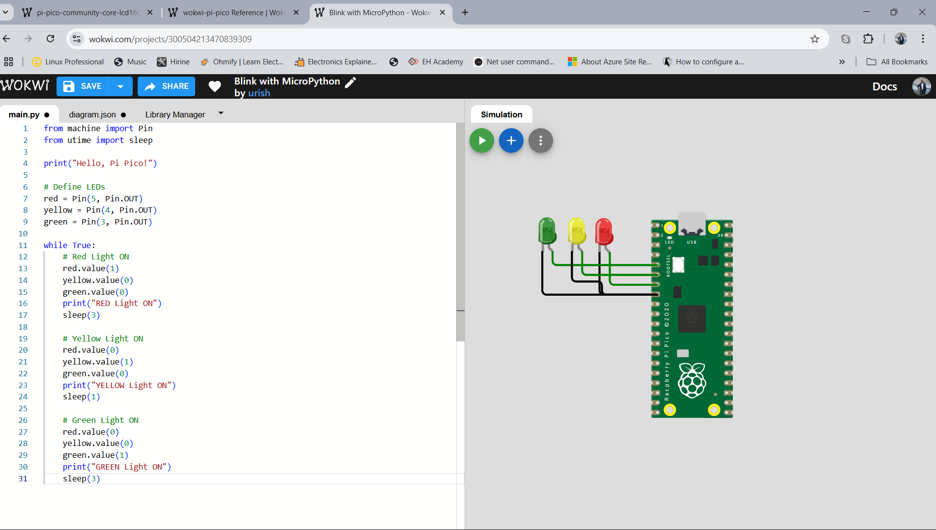
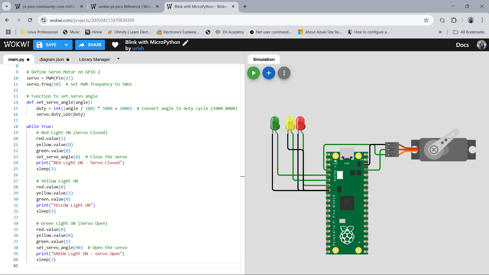
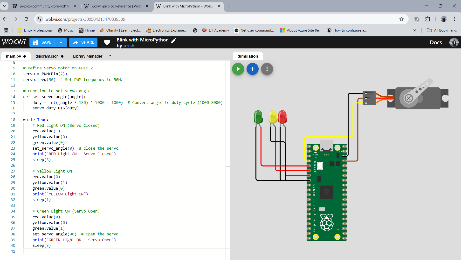
Added servo motor to control the movement based on the light colour.
When green it silent.
 Individual Reflection
- What worked well: Understanding different toolchains and testing Raspberry Pi.
- Challenges: My servo motor does not rotate fully to 90 degrees.
The solution was to change the "set angle method" to this:
I used AI (Chatgpt) to assist in debuging the code with the code and prompt "Motor do not rotate to 90 degrees".
The code before:def set_servo_angle(angle): duty = int((angle / 180) * 5000 + 1000) # Convert angle to duty cycle (1000-8000) servo.duty_u16(duty)
Corrected code:
def set_servo_angle(angle):

      min_duty = 1638   # ~5% of 65535

      max_duty = 8192   # ~12.5% of 65535

      duty = int(min_duty + (angle / 180) * (max_duty - min_duty))

      servo.duty_u16(duty)
- Future Improvements: Exploring RTOS for ARM and ESP32, testing Raspberry Pi for real-time applications.
reference book: Link.