Week 9- Input Devices
Group Assignment
Probe an input device's analog levels and digital signals.
Document your work on the group work page and reflect on your individual page what you learned.
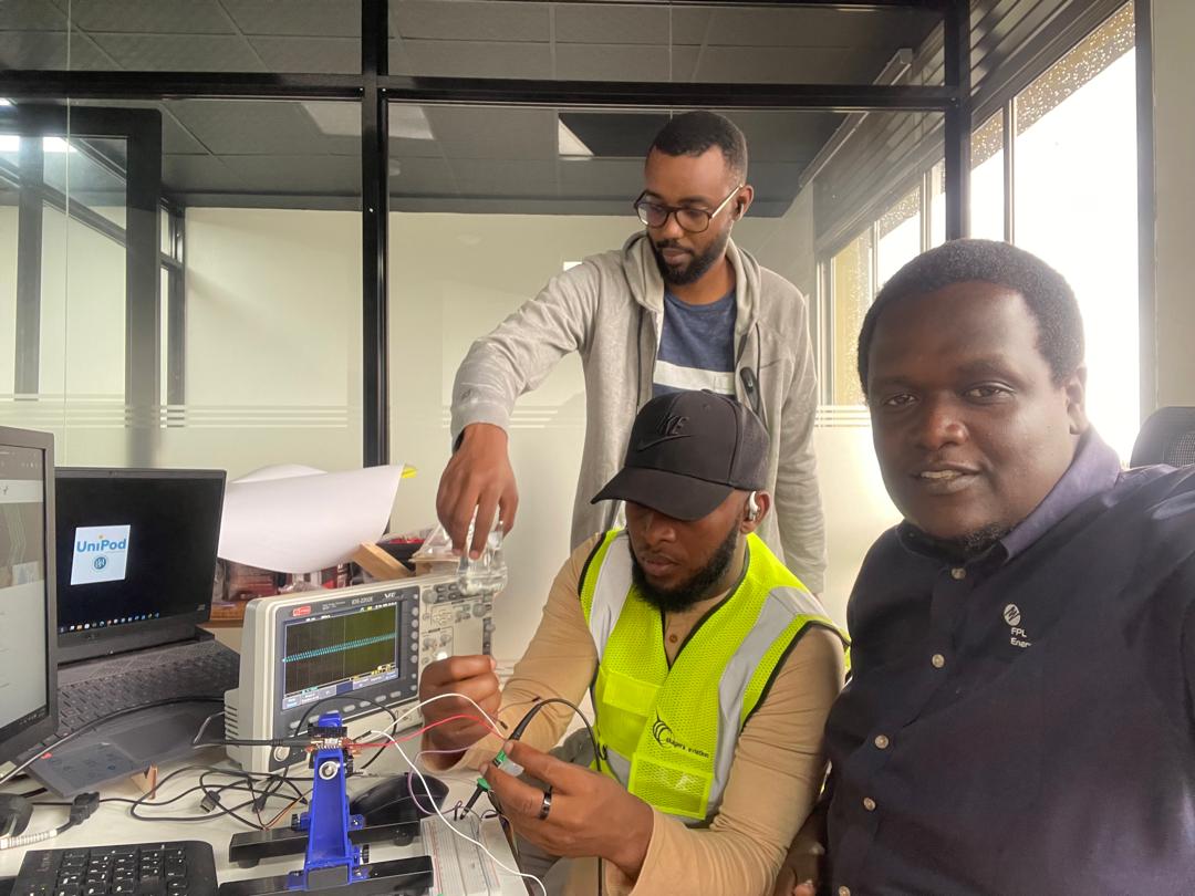 Team Kigali members working on input device analysis
 Hero image
Introduction to Input Devices
Input devices are hardware components that allow users to input data and control signals into a computer or other electronic devices. They serve as the primary means of interaction between users and machines, enabling the transfer of information and commands. This week, we focused on understanding the behavior of different input devices by probing their analog levels and digital signals using oscilloscopes and multimeters. The hands-on experience helped us understand how sensors convert physical phenomena into electrical signals that can be processed by microcontrollers.
About Input Device Classification
Input devices can be classified in several ways based on their functionality and signal characteristics:
- Passive vs Active Sensors: Passive sensors generate signals without external power, while active sensors require power to operate
- Analog vs Digital Outputs: Analog sensors provide continuous voltage levels, while digital sensors output discrete states
- Contact vs Non-contact: Some sensors require physical contact, others work remotely
- Signal Processing: Understanding how to interpret and condition sensor signals
- Interfacing: Methods to connect sensors to microcontrollers and processing systems
In our lab, we explored both Digital and analog sensors to understand their different characteristics and signal behaviors.
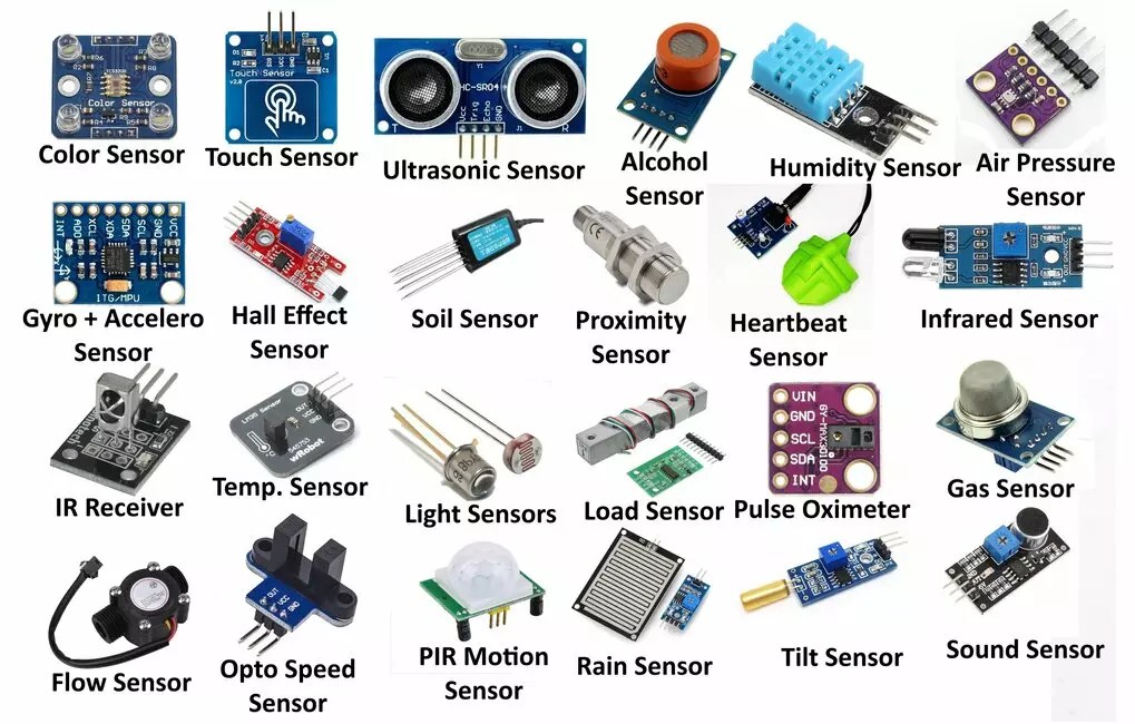 Input Device as sensor we have discussed
Our Selected Input Devices
For this assignment, Team Kigali decided to probe two different types of input devices to explore the differences in their signal characteristics and behavior:
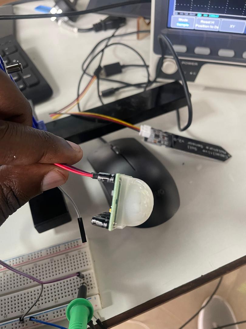 PIR (Passive Infrared) Sensor - Example of a digital sensor
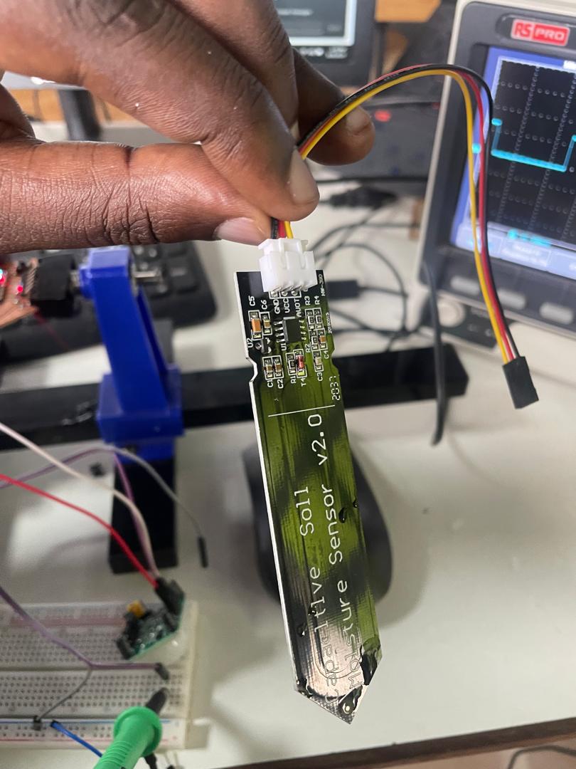 Capacitive Soil Moisture Sensor - Example of an analog sensor
PIR Sensor (Passive Infrared) - Passive Digital Sensor
The PIR sensor is an excellent example of a passive sensor that detects motion by measuring changes in infrared radiation. It operates without requiring external power for the sensing element itself, generating a signal when it detects movement of warm objects (like humans or animals) within its field of view.
- Operating Principle: Detects changes in infrared radiation using pyroelectric elements
- Output Type: Digital signal (HIGH/LOW)
- Power Requirement: Requires power for signal conditioning but not for sensing
- Applications: Motion detection, security systems, automatic lighting
Capacitive Soil Moisture Sensor - Active Analog Sensor
The capacitive soil moisture sensor measures the moisture content in soil by detecting changes in the dielectric constant of the surrounding medium. It provides a continuous analog output proportional to the moisture level.
- Operating Principle: Measures capacitance changes due to moisture content
- Output Type: Analog voltage signal (continuous)
- Power Requirement: Requires external power for operation
- Applications: Smart irrigation, plant monitoring, agriculture automation
PIR Sensor Testing Process
We conducted comprehensive testing of the PIR sensor to understand its digital signal characteristics:
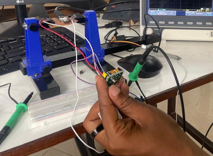 PIR sensor connected to oscilloscope for signal analysis
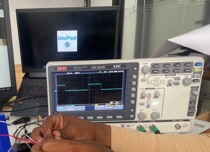 PIR sensor digital signal displayed on oscilloscope
Testing Procedure
- Circuit Setup: Connected PIR sensor VCC to 5V, GND to ground, and output to oscilloscope Channel 1
- Oscilloscope Configuration: Set time base to capture the sensor's response time (typically 2-5 seconds)
- Baseline Recording: Recorded the sensor output with no motion present
- Motion Testing: Introduced controlled motion at various distances and speeds
- Signal Analysis: Measured rise time, fall time, and signal duration
PIR Sensor Observations
- Idle State: Output remains LOW (0V) when no motion is detected
- Motion Detection: Output goes HIGH (3.3V) when motion is detected
- Response Time: Approximately 100-500ms to respond to motion
- Hold Time: Signal remains HIGH for 2-5 seconds after motion stops
- Signal Quality: Clean digital transitions with minimal noise
Video showing PIR sensor response to motion with oscilloscope display
Capacitive Soil Moisture Sensor Testing
We performed detailed analysis of the capacitive soil moisture sensor to understand its analog signal behavior:
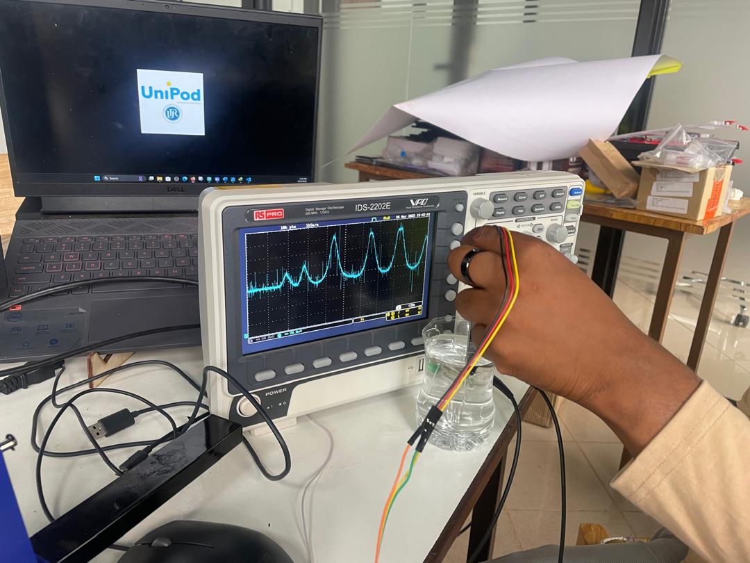 Analog signal from moisture sensor displayed on oscilloscope
Testing Procedure
- Circuit Setup: Connected sensor VCC to 3.3V, GND to ground, and analog output to oscilloscope
- Dry Condition: Measured sensor output when completely dry (in air)
- Moisture Levels: Tested sensor in varying moisture conditions using water
- Dynamic Testing: Observed signal changes as moisture level varied
Video showing dynamic moisture sensor testing with real-time oscilloscope display
Conclusions and Design Guidelines
Through our comprehensive testing of both passive and analog input devices, we gained valuable insights:
This week provided hands-on experience with input device analysis, from understanding basic sensor principles to practical implementation considerations. The combination of oscilloscope and multimeter analysis gave us comprehensive insights into sensor behavior that will be invaluable for future electronics projects. We now have a solid foundation for selecting, testing, and integrating various input devices in our designs.
The practical experience with both passive and active sensors, combined with analog and digital signal analysis, has prepared us to make informed decisions about sensor selection and interface design in our future embedded systems projects.