Assignment Brief:
- This week is like a free pass to try something new.
- I tried out Metal Cutting and metal etching.
Metal Laser Cutting
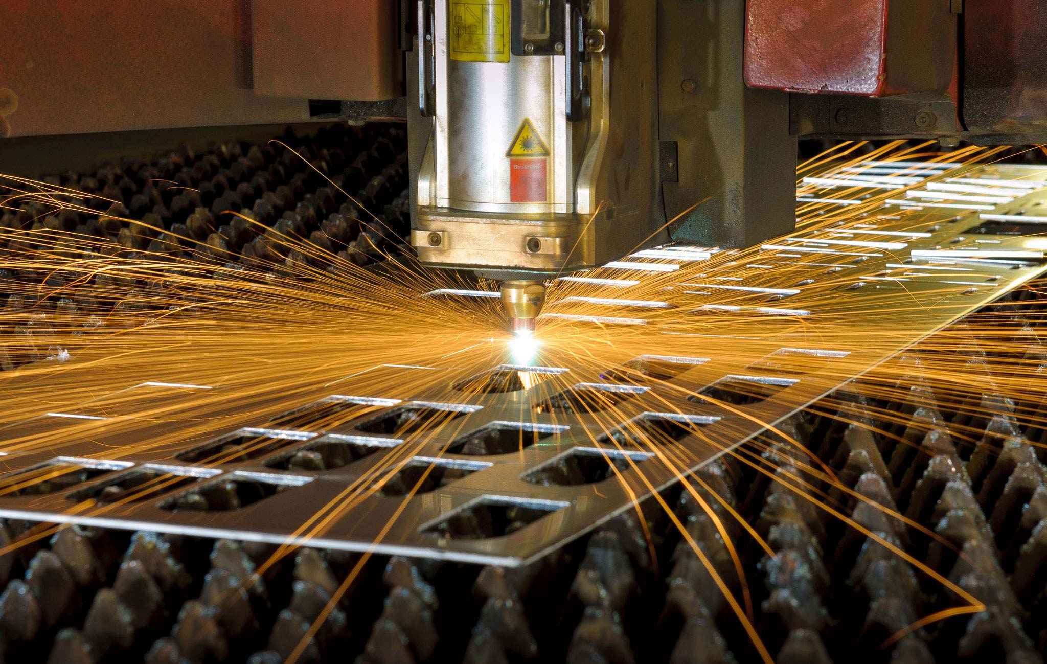
Metal Laser Cutting is a process that uses a high-powered laser beam to cut through metal materials with high precision and accuracy. It’s widely used in industries like automotive, aerospace, manufacturing, and architecture due to its speed, accuracy, and ability to handle complex geometries.
How It Works:
- Laser Generation: A laser source (e.g., CO₂, fiber, or Nd:YAG) produces a focused beam of light.
- Beam Focusing: The laser beam is directed through lenses and mirrors to a fine point on the metal surface.
- Melting or Vaporizing: The intense heat melts or vaporizes the material.
- Assist Gas: A high-pressure gas (oxygen, nitrogen, or air) removes molten material.
Comparison of Metal Cutting Machines
Utilizes a high-powered laser beam to cut through metal sheets or plates. Offers high precision and versatility, capable of cutting intricate designs and patterns. Suitable for a wide range of metals, including steel, stainless steel, aluminum, brass, and copper. Can produce clean, burr-free edges with minimal material waste. Generally faster than traditional cutting methods and allows for automation.
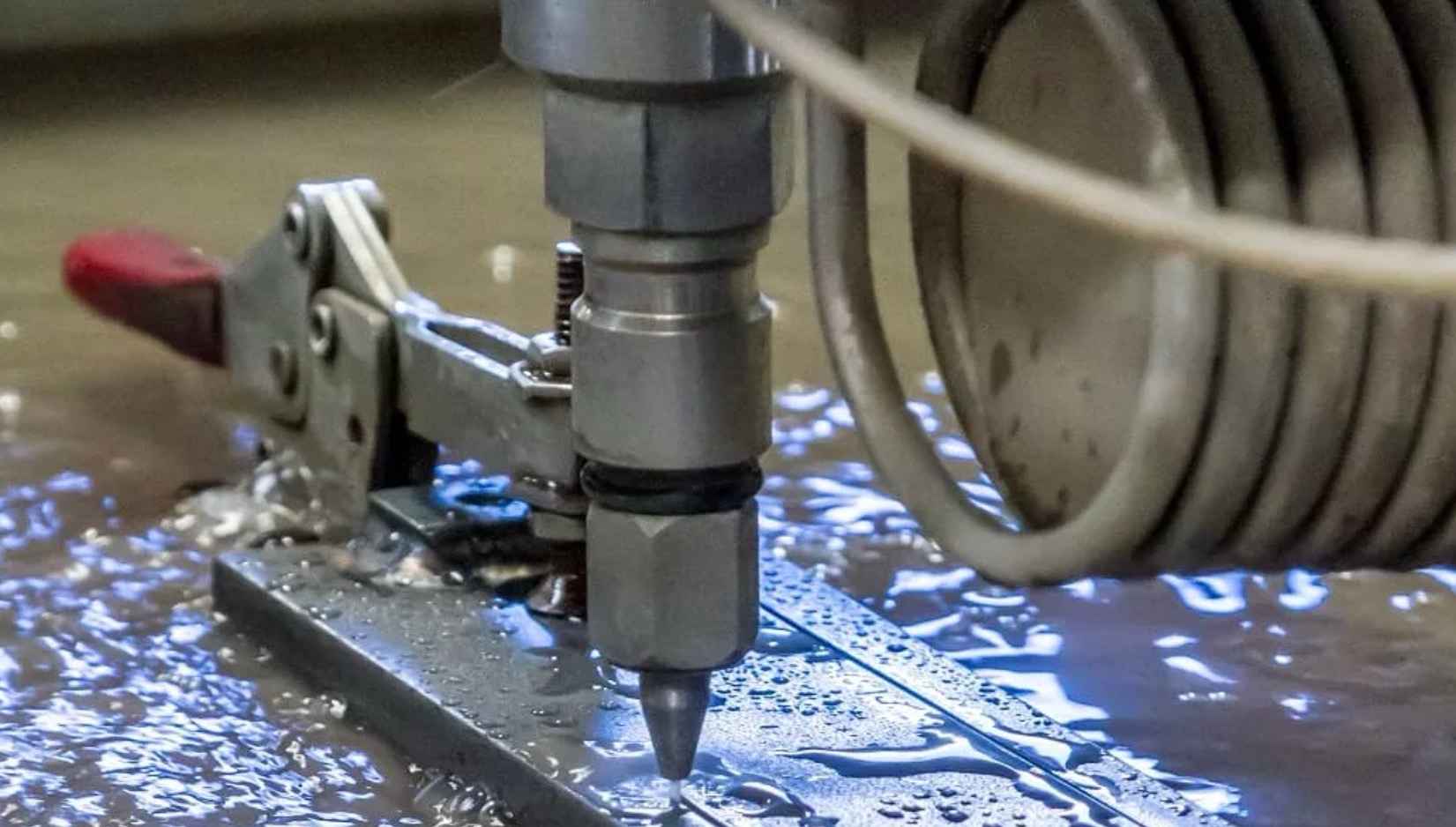
Uses a high-pressure stream of water mixed with abrasive particles to cut through metal. Ideal for cutting thick materials or materials sensitive to heat, such as titanium, stone, and glass. Does not generate heat-affected zones (HAZ) and minimizes the risk of material distortion or warping. Can cut through reflective or non-conductive materials without the need for special adjustments. Offers excellent precision and can produce intricate shapes and contours.
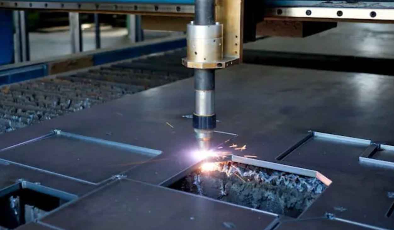
Utilizes a high-temperature plasma arc to melt and cut through metal. Suitable Suitable for cutting
conductive metals such as steel, stainless steel, aluminum, and copper. Offers high cutting speeds
and is particularly effective for thick materials. Generates heat-affected zones (HAZ) along the cut
edges, which may require additional post-processing. Typically used for industrial applications
requiring high productivity and cost-effective cutting.
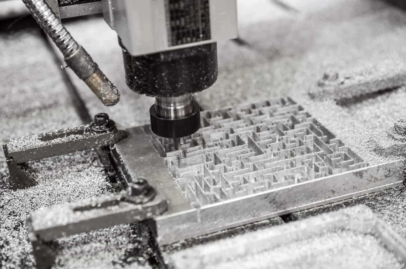
Employs rotating cutting tools to remove material from a solid metal workpiece. Capable of milling complex shapes, contours, and features with high precision. Suitable for a wide range of metals, including steel, aluminum, brass, and titanium. Offers versatility for both roughing and finishing operations, such as drilling, tapping, and contouring. Can accommodate various tooling configurations and cutting strategies for optimal efficiency.
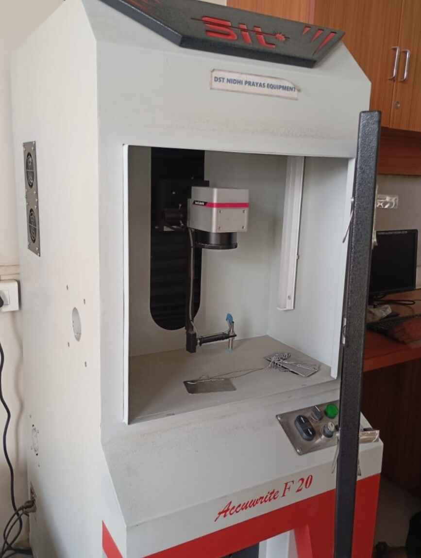
Since we do not have metal cutting machines in-house, we sourced the service from a local workshop vendor. The machine available at the workshop was a high-powered industrial laser cutting machine, which we used to cut our metal components.
I initially wanted to experiment with waterjet cutting, but I learned that it is typically used for cutting materials with high thickness and is not ideal for achieving very intricate designs. Since I was working with a 3mm thick mild steel sheet and aimed to create a detailed design, I decided to go with laser cutting instead.
Cutting Thickness Capabilities:
Laser Cutting-
Stainless Steel (SS): 0.5 mm to 8 mm
Mild Steel (MS): 0.5 mm to 16 mm
Waterjet Cutting:
Stainless Steel (SS): Up to 150 mm (depending on machine power and material quality)
Mild Steel (MS): Up to 200 mm (with excellent edge quality and minimal thermal impact)
Metal laser cutting machine at the workshop
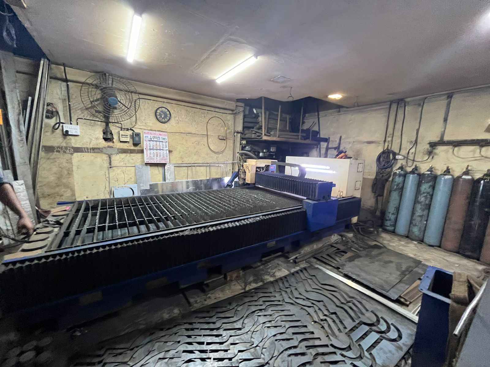
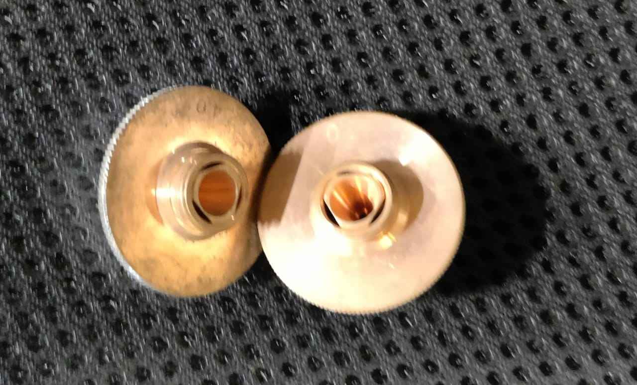
While talking to our vendor we learnt few thing of the machine including Kerf: Approximately 0.2mm. Nozzle Type: The nozzle is changed based on the material being cut to ensure optimal focus, cut quality, and gas flow. Minimum Spacing Between Parts: 5 mm
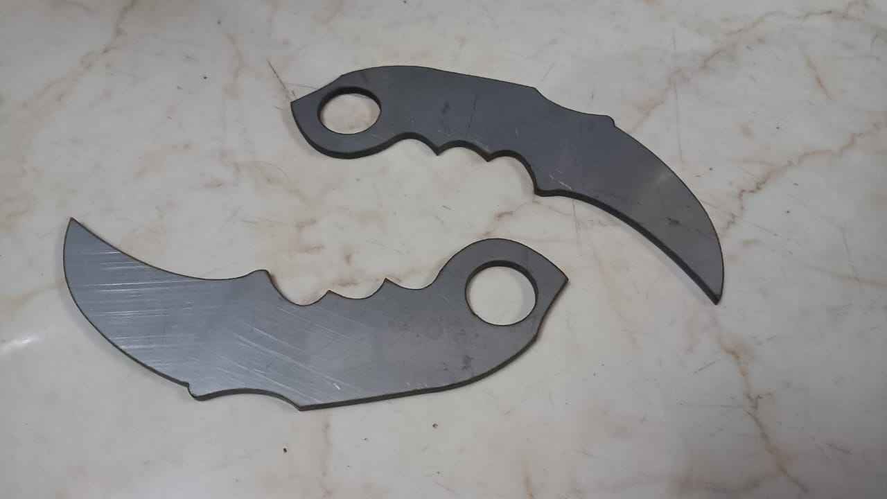
Design
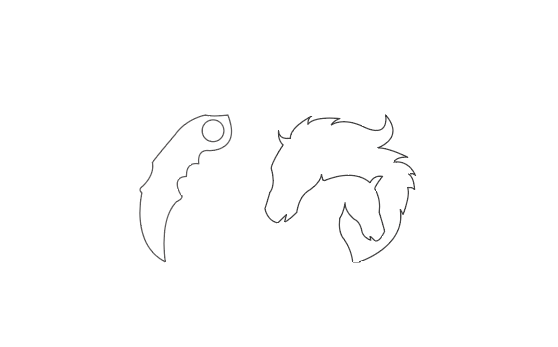
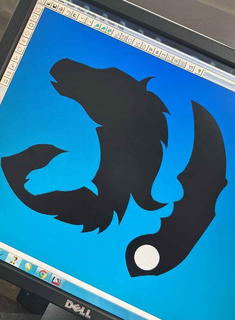
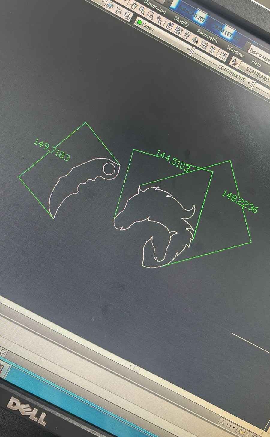
I designed a Karambit knife, this was something I worked over during my college course of Product semantics. The horse file beside mine was my Fab mate Sharvari's File.
Knife Cut design. The file format I sent to the vendor was DXF
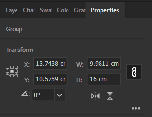
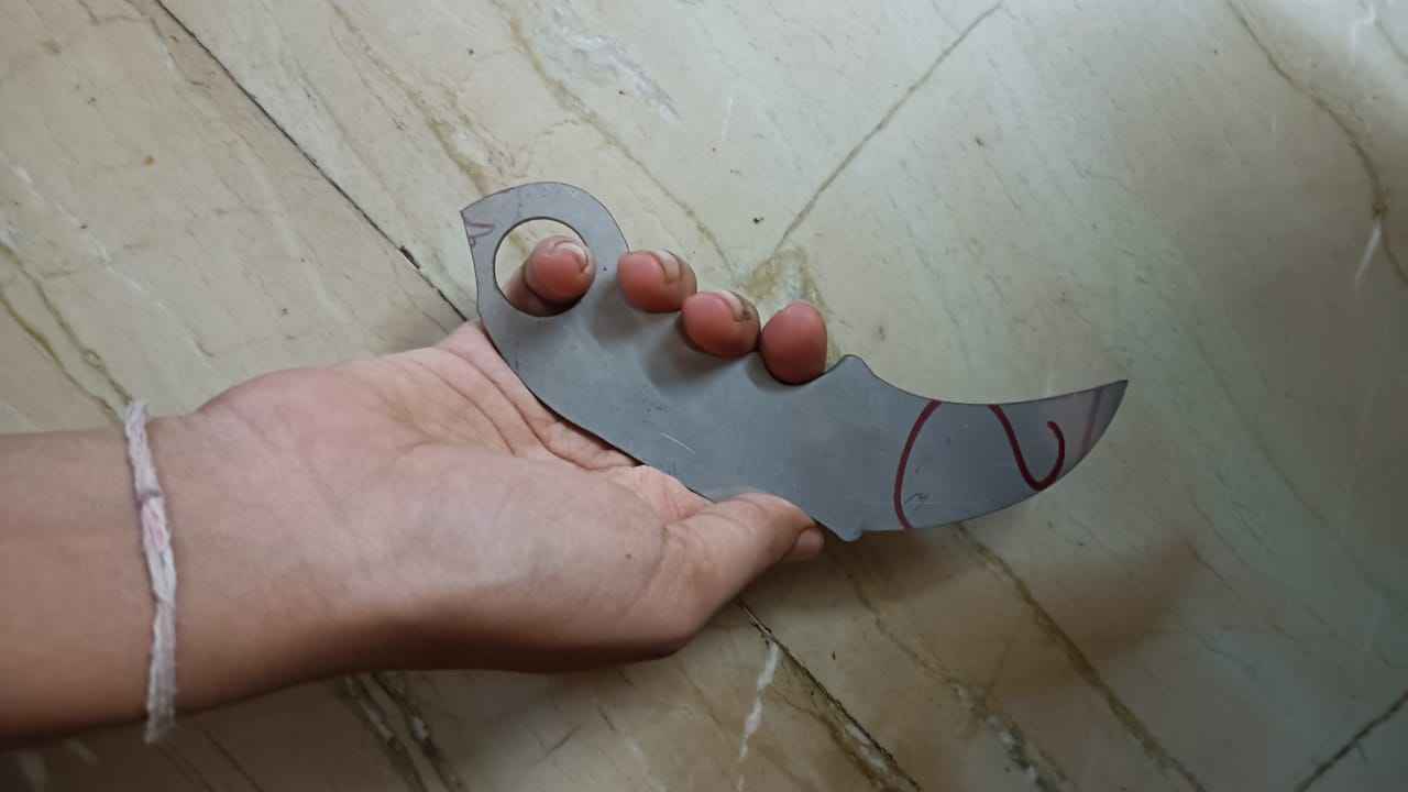
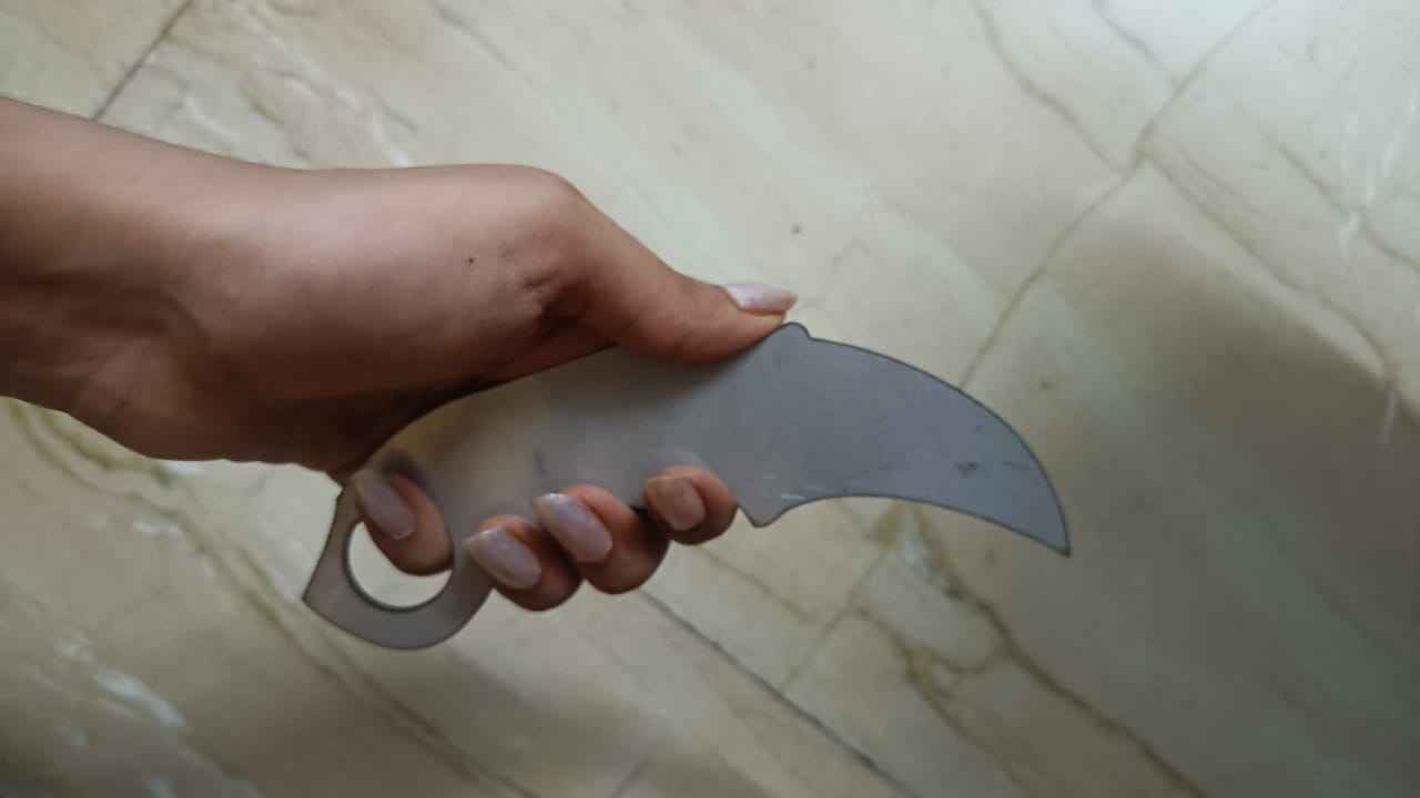
I set the length of the Knife to 16cm, this I set as per the ergonomics of my hand.
Toolpath
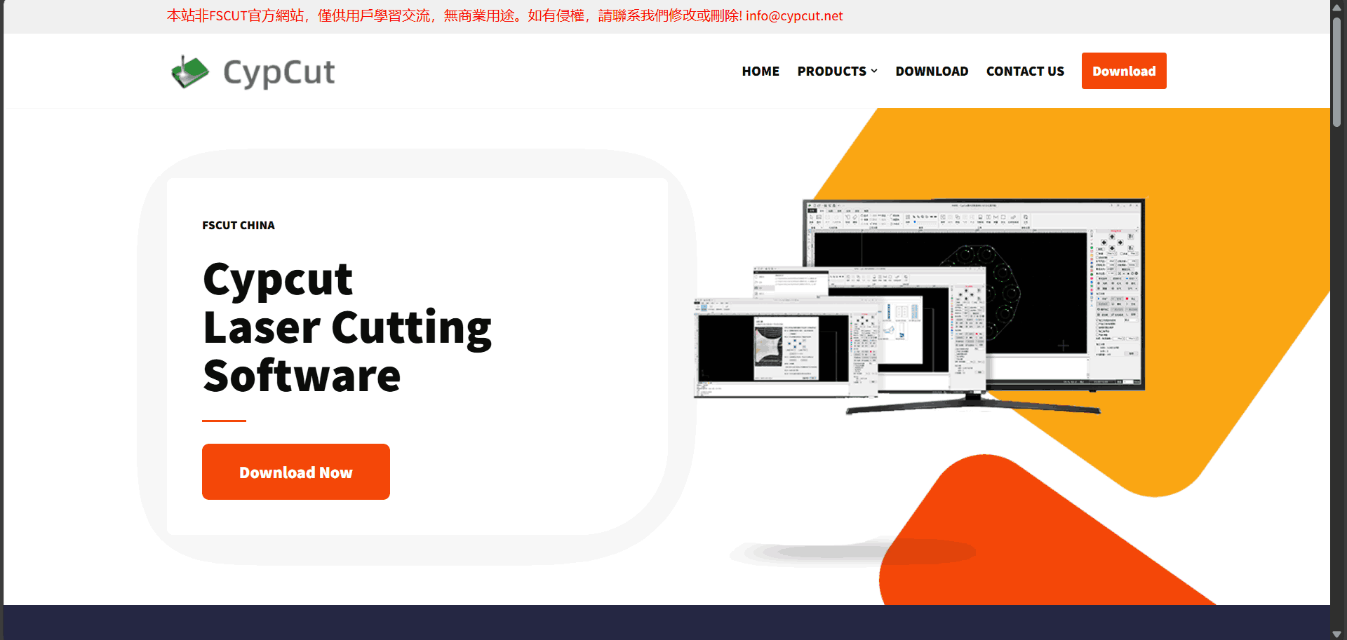
To generate the toolpath, we used CypCut software, which is similar to RDWorks—commonly used in laser cutting—but offers more advanced features and greater control over cutting parameters. Download the software from the link provided here
Steps to Use CypCut Software for Metal Laser Cutting
1. Initial Setup:
a. Power On: Start the laser cutting machine and the computer with the CypCut software
installed.
b. Connect: Ensure the computer is properly connected to the laser cutter via the appropriate
interface (USB, Ethernet, etc.).
2. Import Design File:
b. Import File: Load your design file—commonly in .dxf or .svg format—into the workspace.
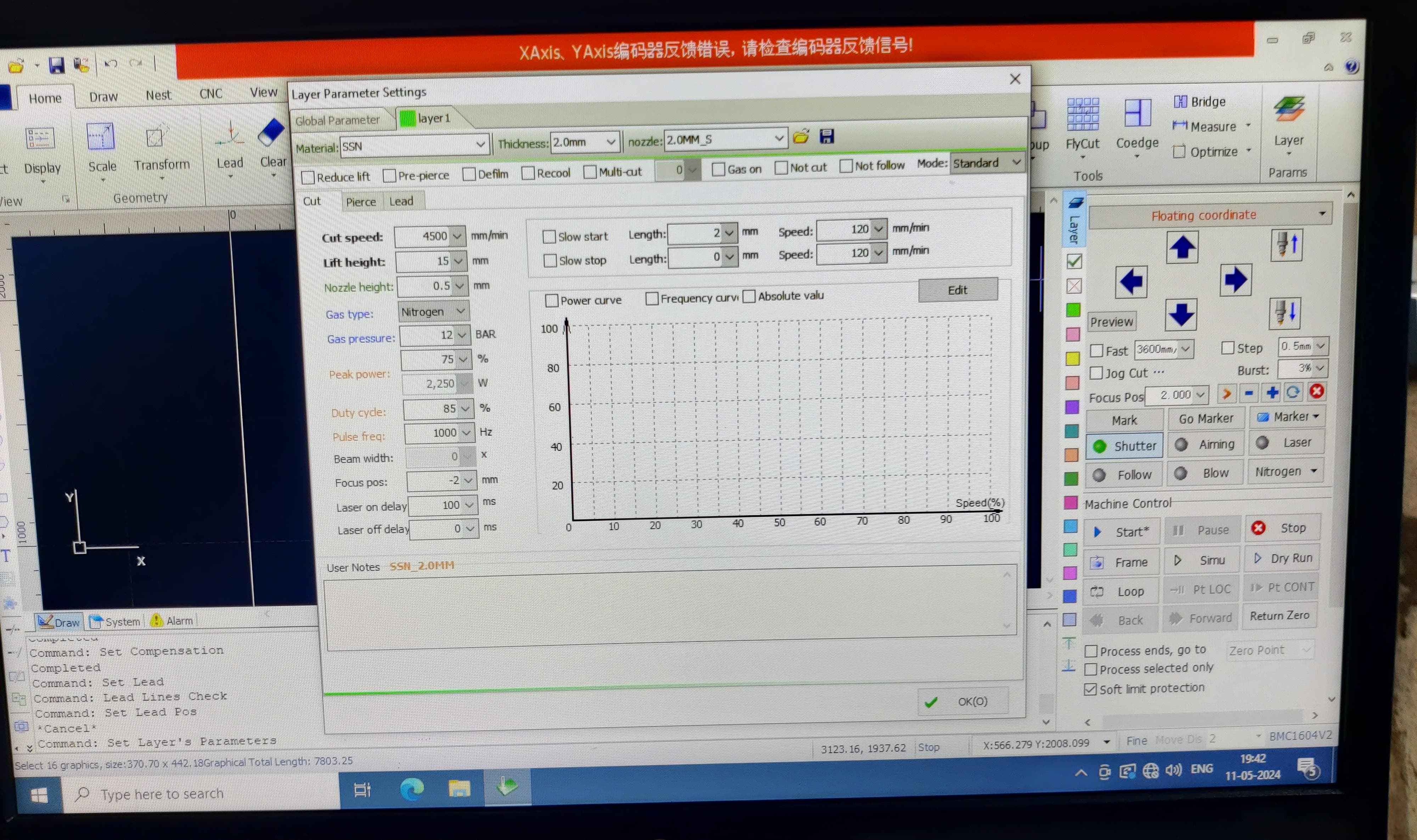
3. Material and Machine Settings:
a. Material Selection: Choose the metal type (e.g., stainless steel, aluminum, mild steel).
b. Thickness Input: Enter the thickness of the metal sheet.
c. Cutting Parameters: Configure the laser power, cutting speed, and gas pressure based on the
selected material and its thickness.
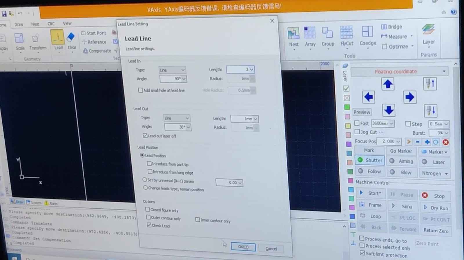
 Lead Line Settings in CypCut
a. Access Lead Line Settings: Navigate to the Lead Line Settings tab within CypCut to configure how the laser begins and ends each cut.
b. Lead-In:
Type: Choose the lead-in type—straight or arc—based on your design and material.
Length: Set an appropriate length to allow the laser to ramp up to full power before entering the
actual cut area.
Angle (if applicable): Specify the angle for straight lead-ins to control entry direction.
c. Lead-Out:
Type: Select either a straight or arc lead-out for a smooth exit.
Length: Set a suitable length to ensure a clean finish at the end of the cut.
Angle (if applicable): Adjust the angle for straight lead-outs as needed.
Positioning: Always ensure that both lead-ins and lead-outs begin and end outside the main part
geometry to maintain dimensional accuracy.
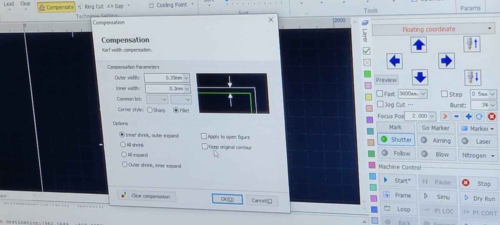 Compensation Settings:
a. Access Compensation Settings:
Go to the Compensation Settings tab in your software interface.
b. Kerf Width Configuration:
Kerf Value: Enter the kerf width—the amount of material removed by the laser during cutting.
Compensation Direction: Select the direction of compensation:
Internal (Negative Kerf): For inside cuts.
External (Positive Kerf): For outside cuts.
c. Offset Adjustments:
Apply appropriate offsets to maintain precise final dimensions of the cut parts.
d. Automatic vs. Manual Compensation:
Choose between automatic compensation (software calculates and applies kerf) or manual compensation
(user-defined settings) based on your project needs.
Additional Settings:
a. Lead Line and Compensation Verification: Check that lead lines and compensation settings are
applied correctly to all cutting paths.
b. Simulation: Run a simulation in CypCut to verify the toolpath, ensuring the lead lines and
compensation settings are correct.
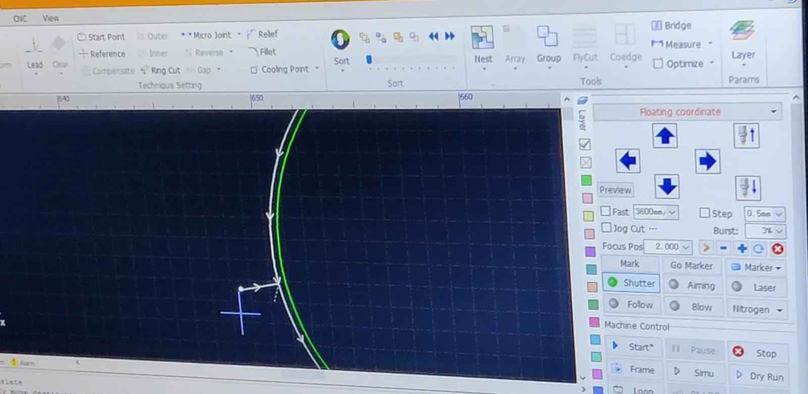
Generate Toolpath:
Create the toolpath and export it as a cutting program file (commonly in .nc or .cnc format).
Transfer to Machine: Save the toolpath file onto a USB drive, then insert it into the laser cutter’s controller for execution.
Machine Setup:a. Insert Toolpath File:
From the machine’s controller, locate and select the appropriate toolpath file.
b. Set Speed and Feed:
Enter the recommended cutting speed and feed rate according to the material type and thickness.
c. Set Origin:
XY Origin: Align the XY origin to the corner of the bed or the reference point defined in your
toolpath file.
Z Origin (Using the Paper Method):
a. Lower the tool until the tip just touches the material surface.
b. Raise it slightly and slide a thin piece of paper beneath the tool.
c. Gradually lower the tool until you feel slight resistance between the paper and the tool—this
indicates proper Z height.
a. Ensure all safety protocols are in place (e.g., wearing safety glasses, securing the
material).
b. Start the cutting process from the machine's controller.
c. Monitor the process to ensure it runs smoothly.
To see the detailed video of how to make toolpath, click here: Part1 And here: Part 2
Cutting process
The Material I used is MS: 3mm. After changing the nozzle we adjusted the origing and checked the frame for cutting and then the cutting started. This is how the Nozzle looked like:
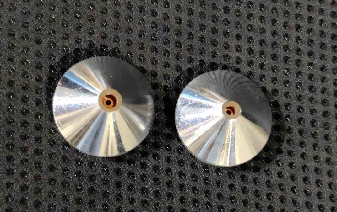
Cutting Process
At the vendor place we also saw a haudralic press to build bowls.
Metal Engraving
Fibre Laser Marking
A fiber laser marking machine is a type of laser engraving or marking system that uses a fiber laser
source to
create high-contrast, permanent marks on various materials. It is widely used in industries for
marking metals,
plastics, and other materials due to its precision, speed, and durability.
Riidl Metal Engrave
SOP.
You can get the details of types of laser cutter in the documentation above.
 . I chose the file which I
made on Adobe Illustrator in my week 02 of Computer Aided design. Learn about my design process from
my
documentation,
Riidl Metal Engrave SOP.
. I chose the file which I
made on Adobe Illustrator in my week 02 of Computer Aided design. Learn about my design process from
my
documentation,
Riidl Metal Engrave SOP.
SAMLight Software
Open the software.
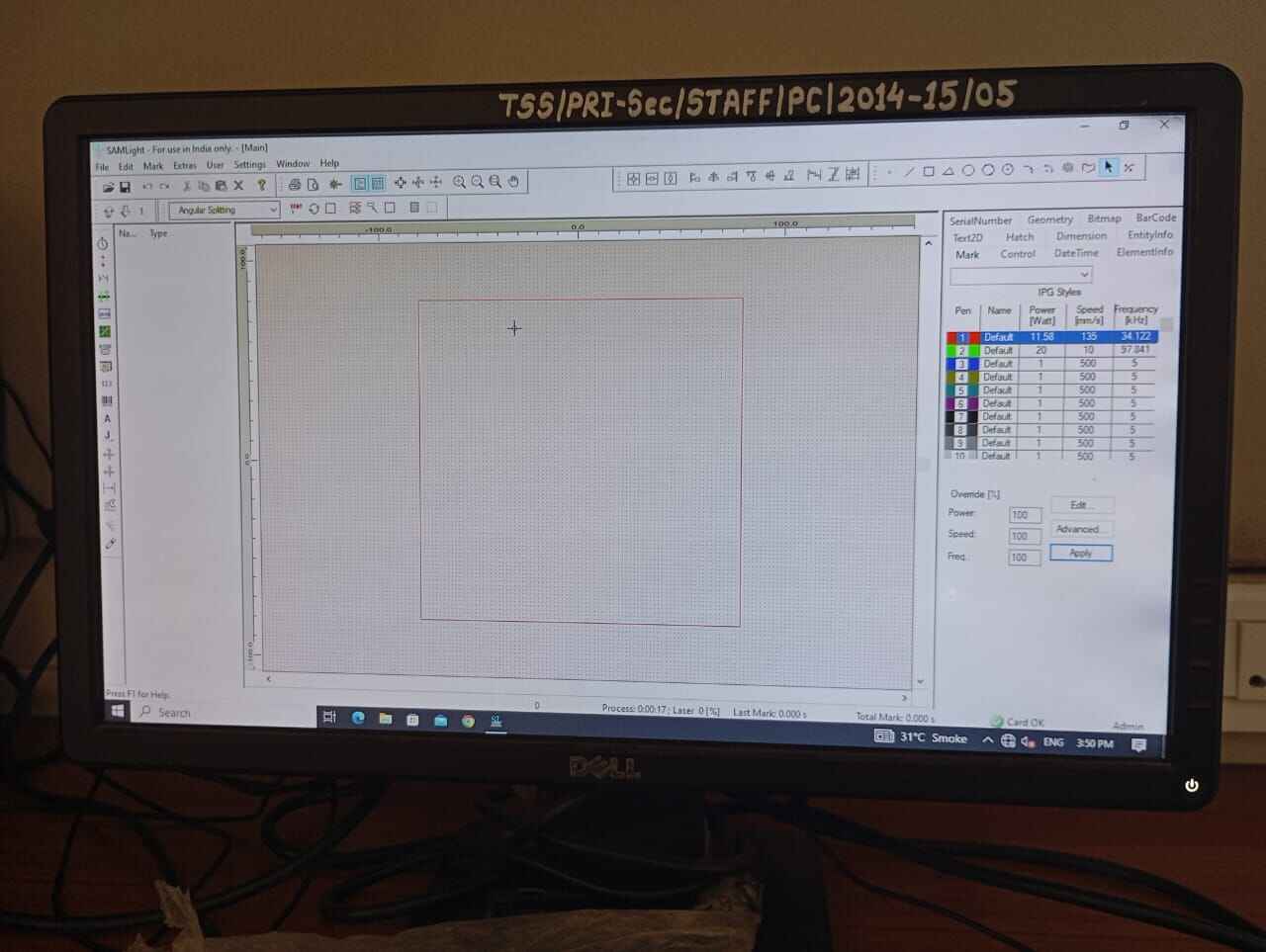
File> Import design
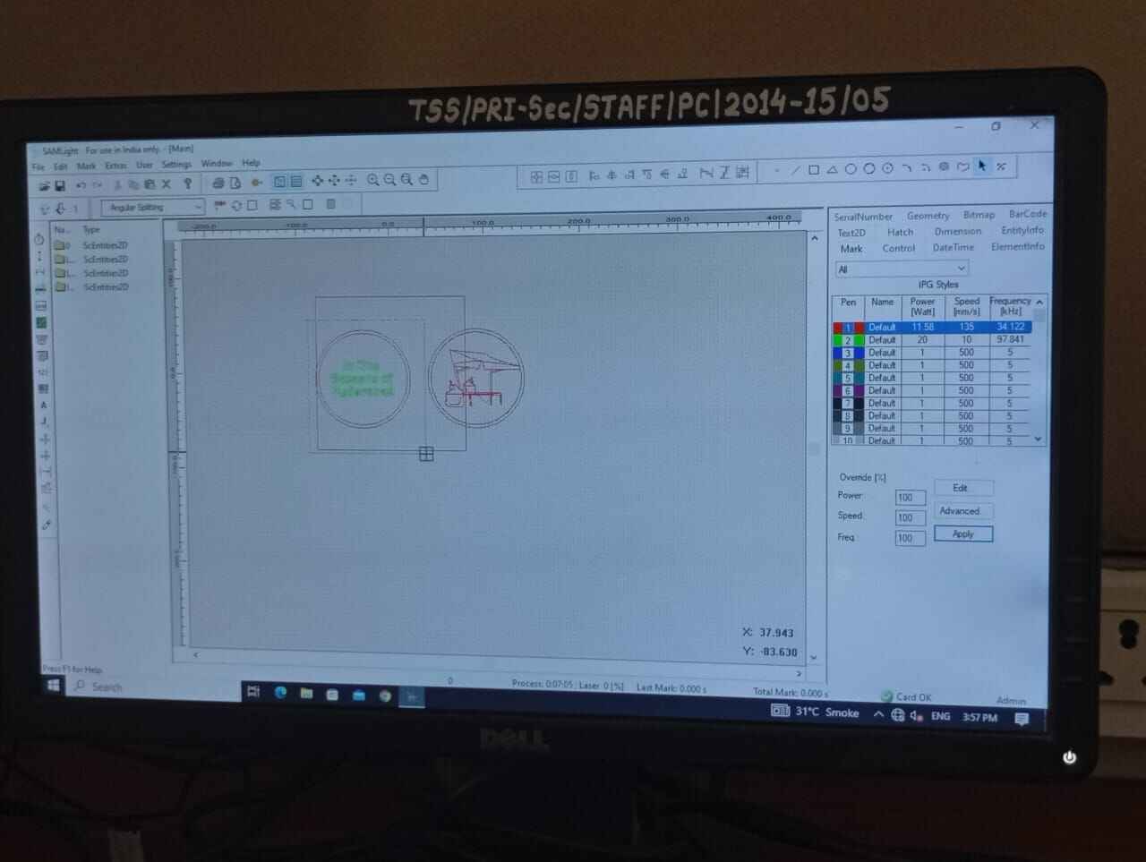
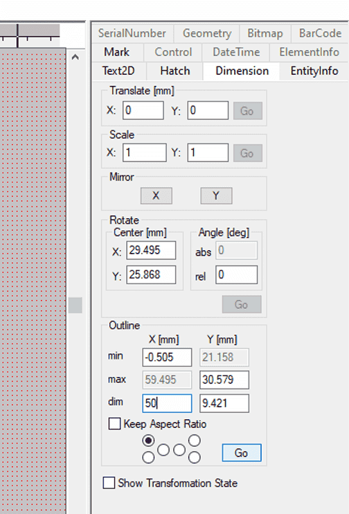
Set the Dimesion of design and external board.
Select the pen colour as your default> apply settings as in image.
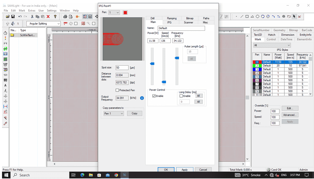
Set the highlighted blue part in the image..
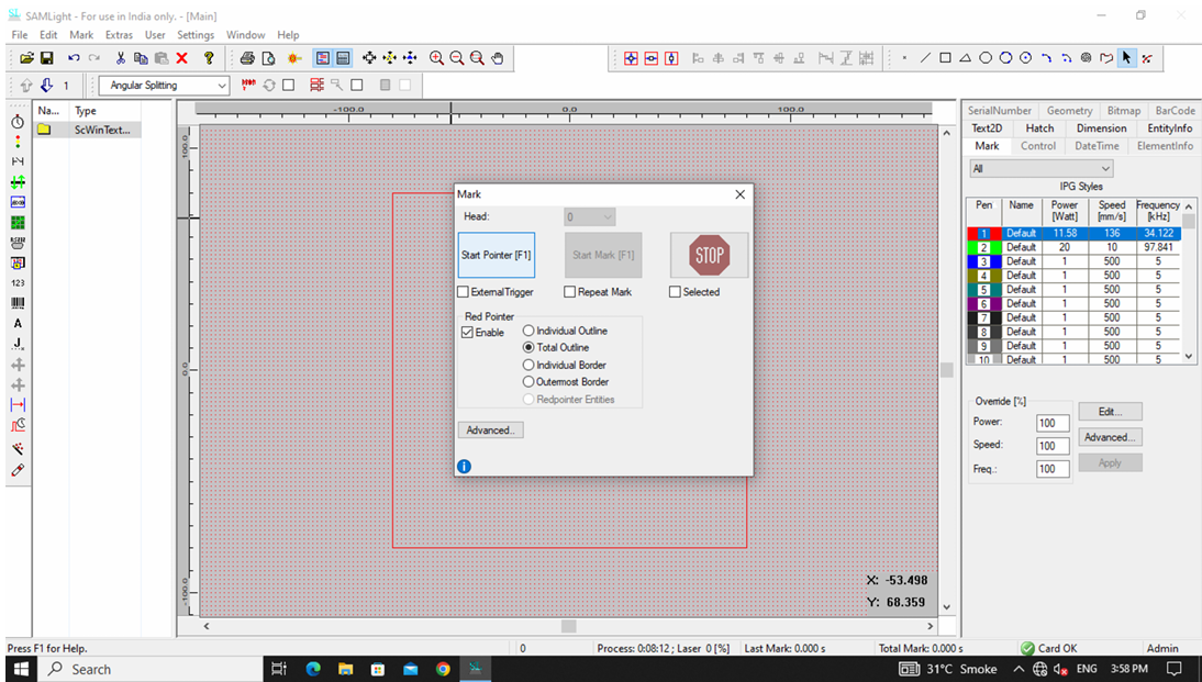
Start pointers.
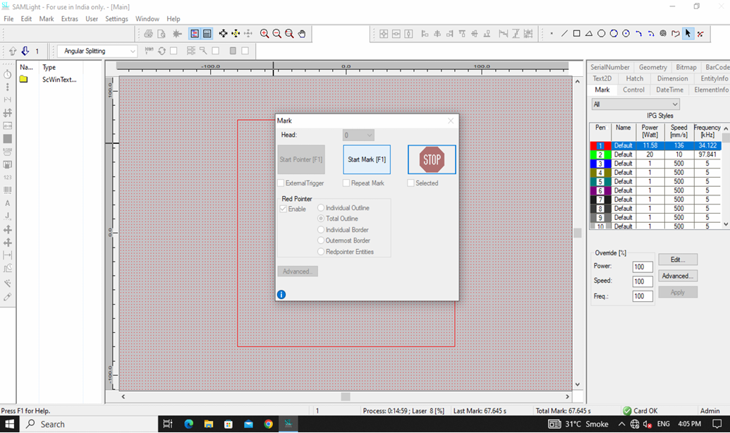
Laser Marking Machine Setup Guide
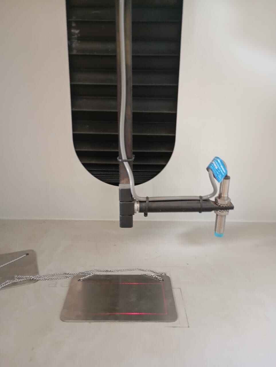
Place the plate at the centre of the beem.
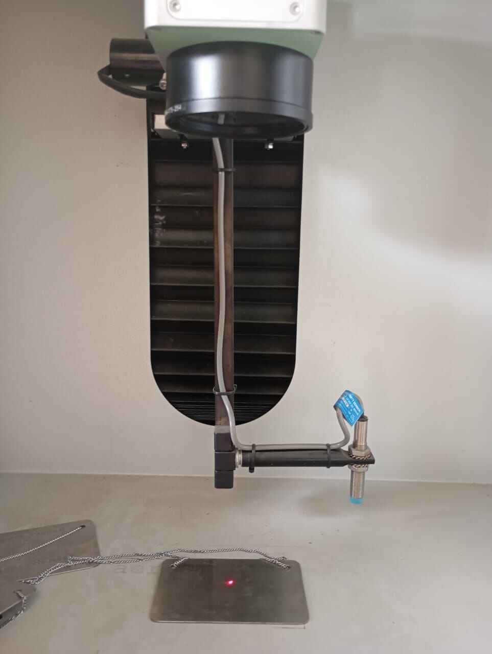
The design dimension frame pops up.
Final Outcome: Hero shot

Learnings
SRM 20 is a metal engraving device which is used for building PCB. A key learning from the above metal engravinging was the metal dust particles. On the SRM20, dangerous metal dust is accumulated at the cut arena. However, on the SIL laser marking machine the laser fumes evaporated the scraped metal. Thus, it is safer to use as you arent in direct contact with the metal fumes.
Another, interesting learning in metal engraving was the liberty in experimenting with engraving thinkness. Firstly, on the guidance of my mentor, I laser engraved the metal only to a slightest which gave a very light engrave only visible in light. Later as an exploration, I tried different thickness of engraving until I got a slight burnt effect on my coin output.
Project Files
Metal Engraving designMetal Cutting design