Assignment Brief:
- Understanding formats: Explore different digital formats, including raster vs. vector, 2D vs. 3D, and techniques like rendering, animation, and simulation.
- Experimenting Softwares: Experiment with software like Rhino, Fusion 360, Illustrator, Inkspace or Blender and convert formats and optimize file sizes.
- Document Final Project: Apply these skills to your final project by modeling, rendering etc. and uploading compressed design files .
Understanding Formats:
2D:
(Two-Dimensional): Objects have only width and height (X and Y axes). Examples: drawings, photographs, and screens.
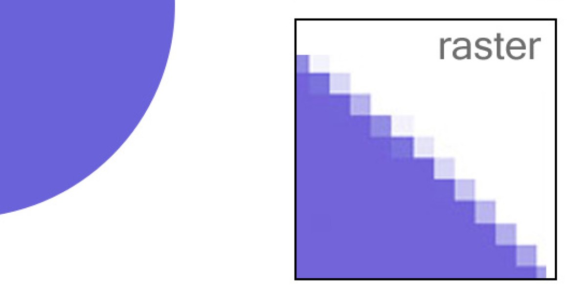
Raster images are made of pixels and are resolution-dependent, meaning they lose quality when scaled. They are best for detailed images like photos and digital paintings. Formats like PNG (Portable Network Graphics), JPEG (Joint Photographic Experts Group), and BMP(Bitmap) support raster graphics, and software like GIMP, Photoshop, and Krita offer pixel-based editing.
Example of raster Image for your understanding:
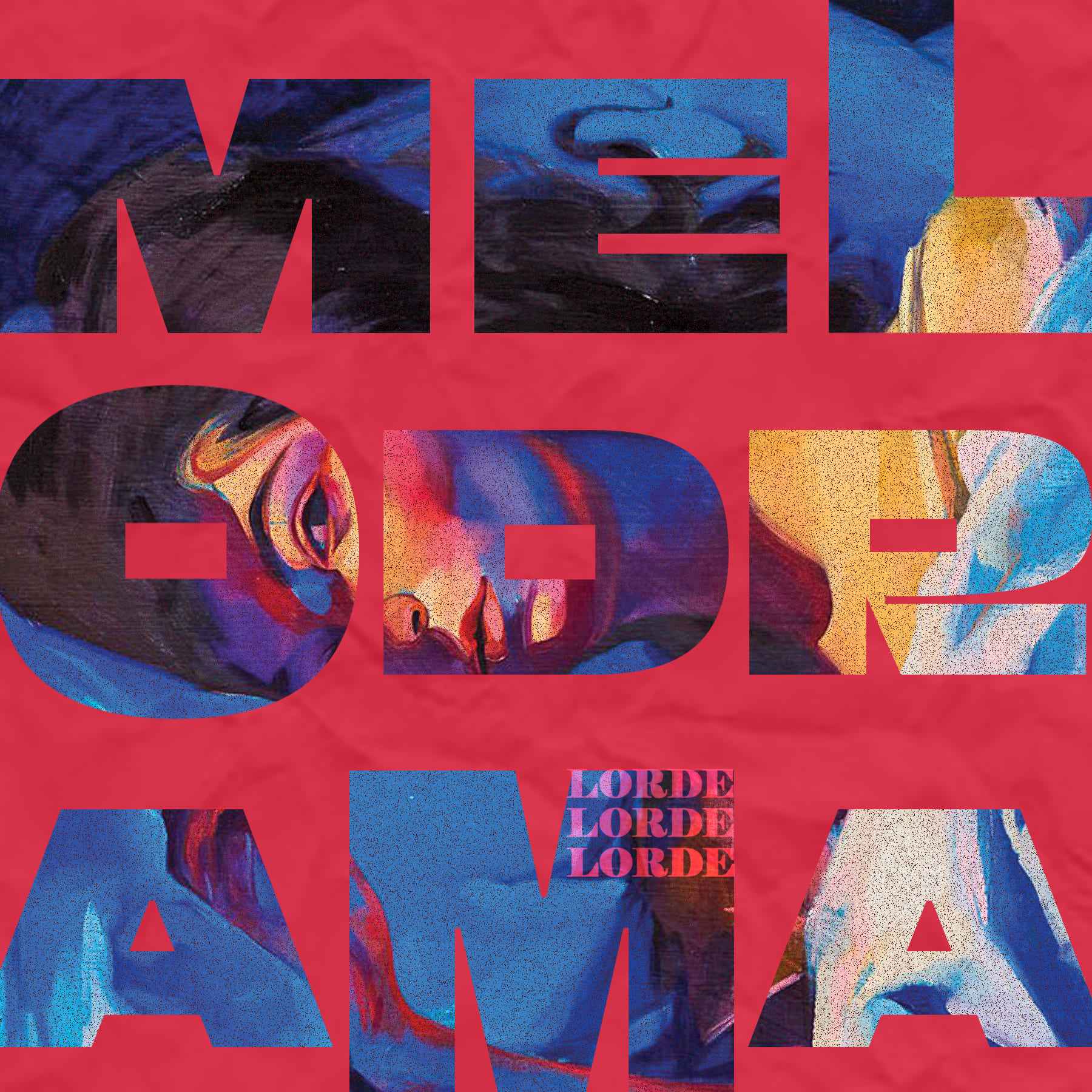
Example of raster Image which I have created on Adobe Photoshop:
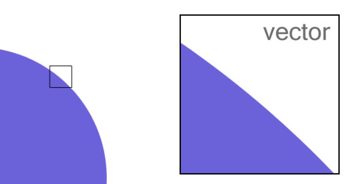
Vector graphics use mathematical equations to create scalable shapes without quality loss, making them ideal for logos, icons, and illustrations. Formats like SVG(Scalable vector graphic), and EPS(Encapsulated Postscript) support vectors, with tools like INKscape, Illustrator, and CorelDRAW providing shape-based design and transformations.
Example of vector Image for your understanding:
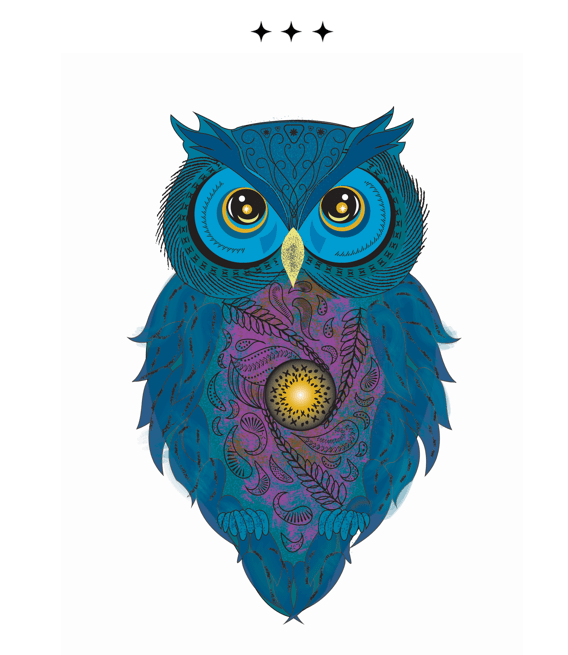
Example of vector Image I have created on Adobe Illustrator:
3D:
(Three-Dimensional): Objects have width, height, and depth (X, Y, and Z axes), making them appear more realistic. Examples: sculptures, 3D models, and real-world objects.
Boundary Representation (BRep) defines 3D objects using surfaces and edges, making it
ideal for CAD modeling and mechanical design. Formats like STEP, IGES, and STL support BRep, with
software like SolidWorks, Fusion 360, FreeCAD, Rhino, and CATIA handling precise geometry.
Functional Representation (FRep) uses mathematical functions to describe objects, enabling
parametric and procedural modeling. Formats like SDF and implicit modeling engines support FRep,
with tools like OpenSCAD, Houdini, Grasshopper (for Rhino), and Autodesk Dynamo offering generative
and algorithmic design.
Volume Representation (VRep) defines objects as volumetric data, commonly used in medical
imaging and simulations. Formats like VTK and NRRD support VRep, with tools like Blender
(Voxel Remesher), 3D Slicer, Magics, and ZBrush (Dynamesh & Sculptris Pro) aiding volumetric workflows.
To deepen my personal understanding, I explored the topics mentioned above and referred to
ChatGPT to further
enhance my knowledge.
Experimenting on Softwares:
This week I worked on understanding and exploring 2D and 3D CAD softwares.
This week’s documentation is divided into these two main categories of exploration:
The softwares I explored were:
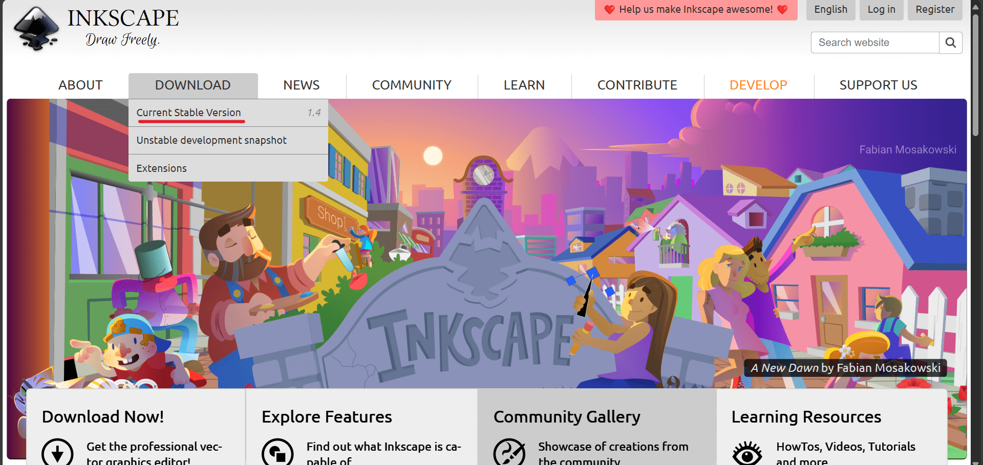
- INKscape: A free, open-source vector graphics editor used for creating
and editing illustrations, diagrams, logos, and complex artwork.
It supports SVG (Scalable Vector Graphics) format and is an alternative to Adobe Illustrator. Download
Inkspace from
here.
- Illustrator: A professional vector graphics editor developed by Adobe, commonly used for creating logos, illustrations, icons, and other scalable artwork. It is a part of Adobe Creative Cloud and is known for its powerful design tools and precision.
- Graphtech Studio 2: A design tool commonly used for preparing artwork and graphics for vinyl cutting. It helps create clean, vector-based designs optimized for plotters and cutters, ensuring precise output for signage, decals, and custom prints. Download for windows here.
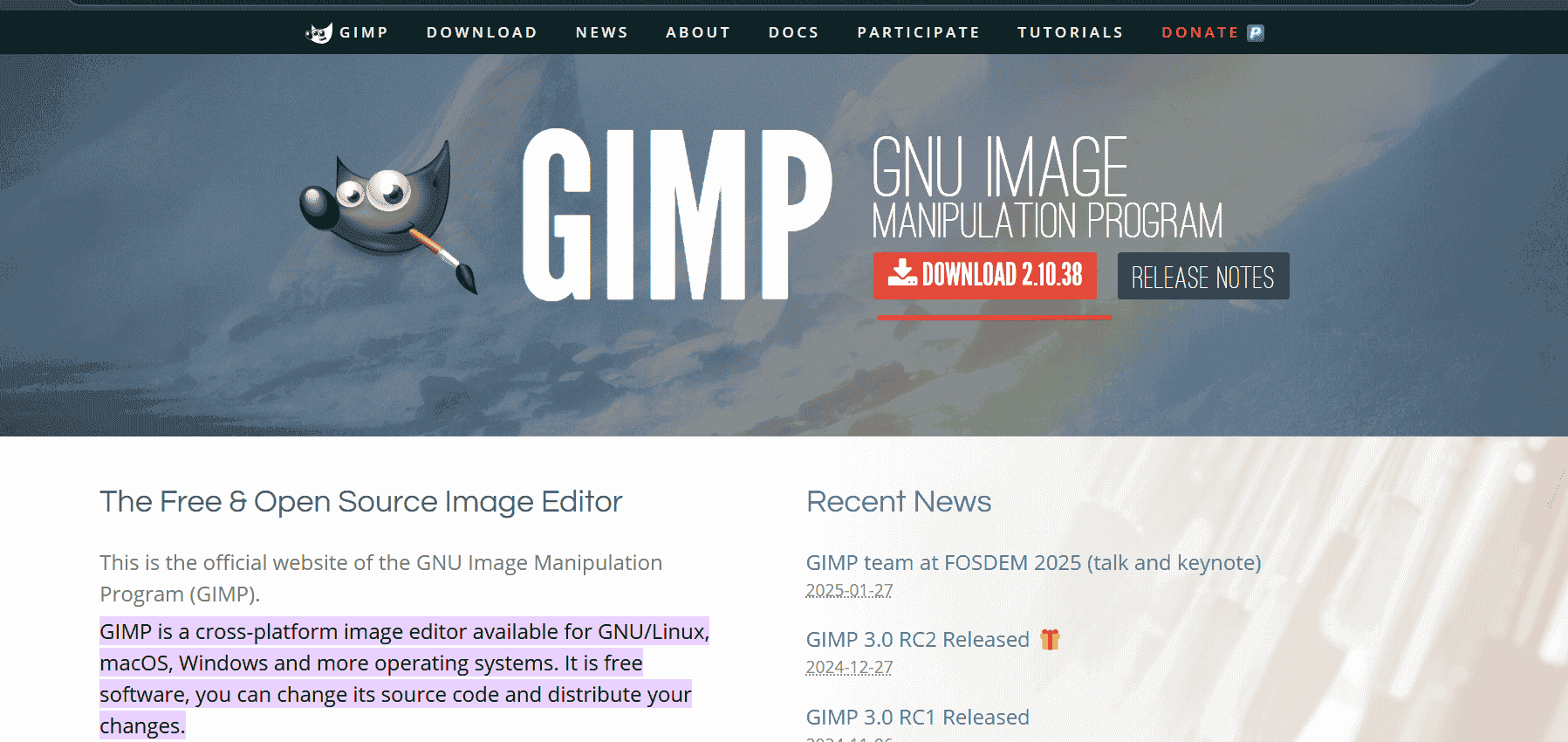
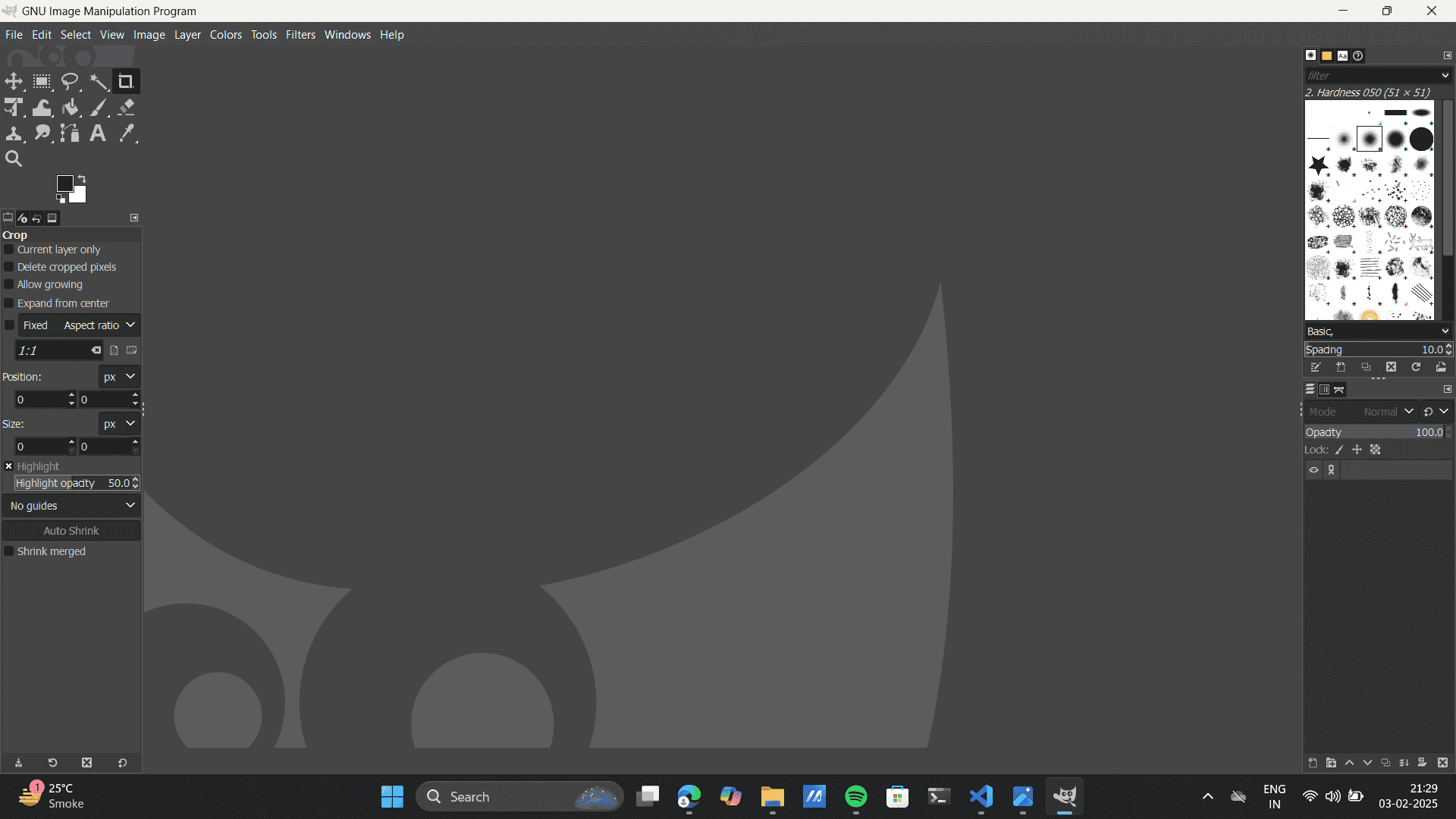
- Gimp: GNU Image Manipulation Program is a free, open-source raster graphics editor. NU stands for "GNU's Not
Unix". It is a recursive acronym that refers to the free and open-source software movement started by the GNU
Project, initiated by Richard Stallman in 1983.
It is often used for photo editing, creating digital artwork, and manipulating images.
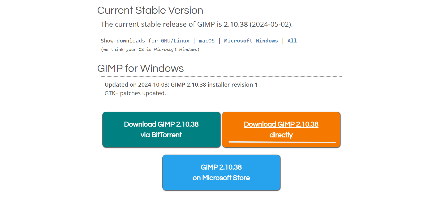
GIMP is a popular alternative to Adobe Photoshop. Download Gimp from
here.
- Photoshop: A widely-used raster graphics editor by Adobe, ideal for editing photos, creating digital artwork, and designing user interfaces. It is known for its advanced image manipulation and retouching features.
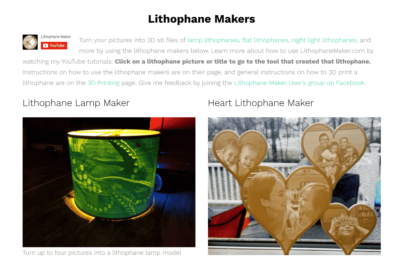
- LithoMaker: A specialized software that converts 2D images into 3D lithophanes—thin,
embossed layers that reveal detailed images when backlit. It processes grayscale images
into depth maps, making them suitable for 3D printing. Explore the website
here.
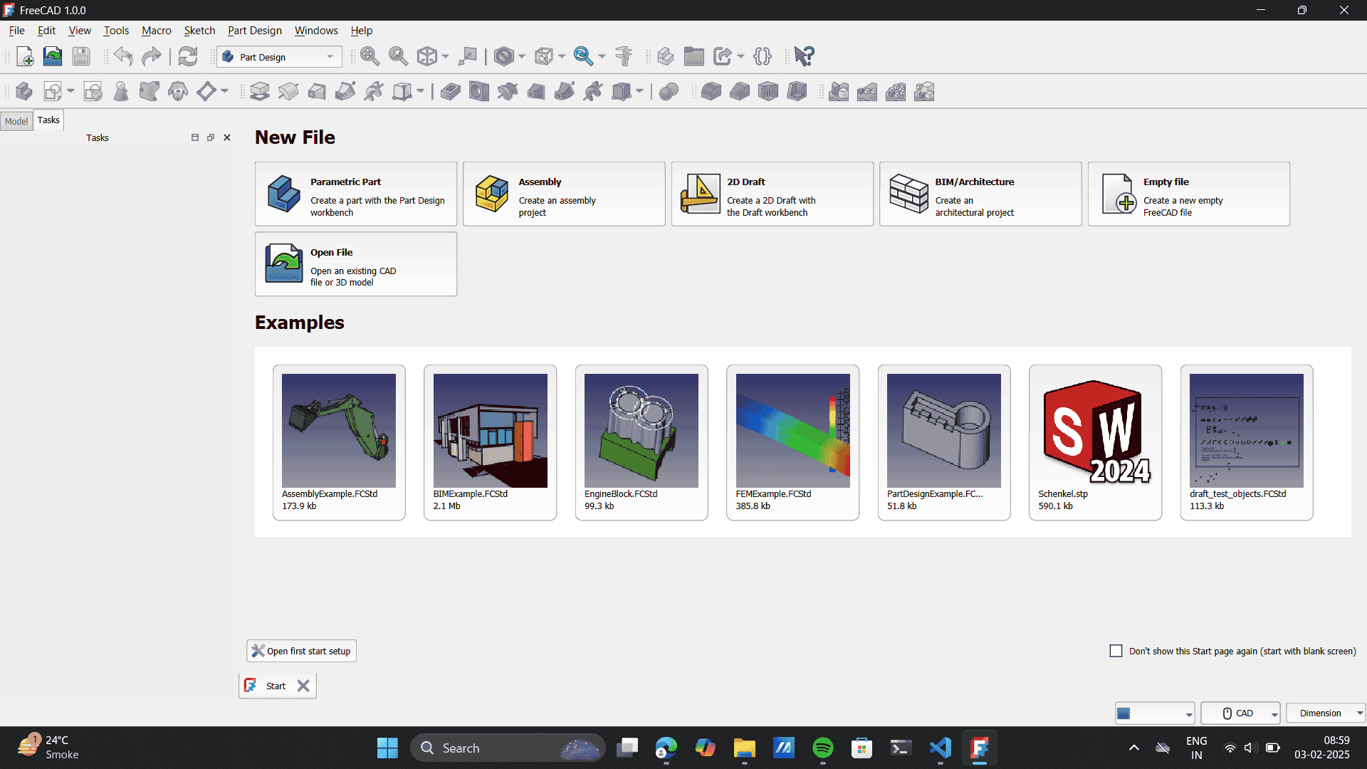
- FreeCad: An open-source parametric 3D CAD (Computer-Aided Design) modeler primarily used for product design, mechanical engineering, and architecture. It’s flexible and customizable, suitable for both amateurs and professionals. Download FreeCAD from here. Incase,you use Mac refer to my semiors documentation: Himanshi Jain for downloading and using FreeCAD for Mac.
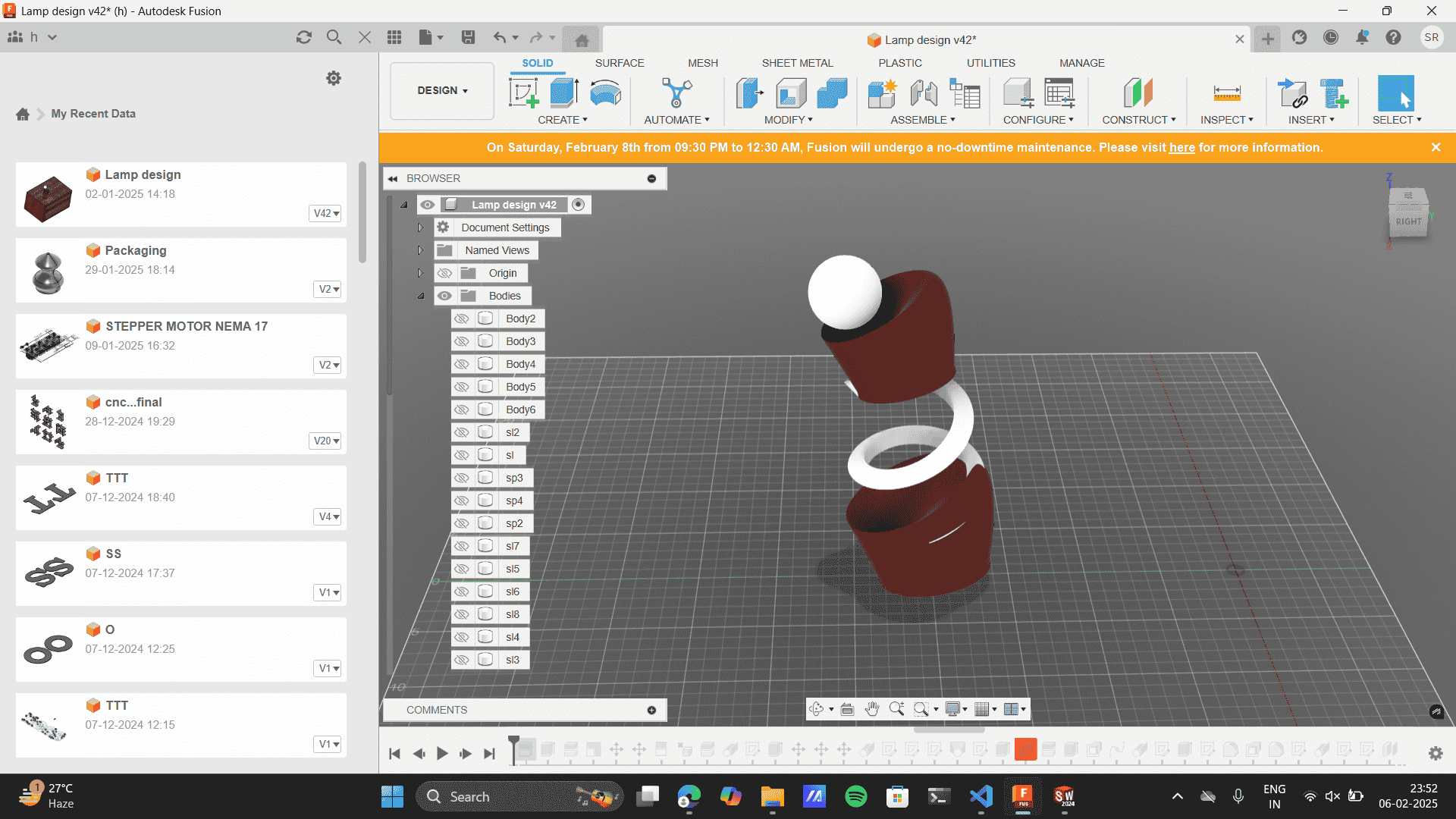
- Fusion 360: A cloud-based 3D CAD, CAM, and CAE tool developed by Autodesk. It integrates design, engineering, and manufacturing into one platform, enabling collaborative product development and prototyping.
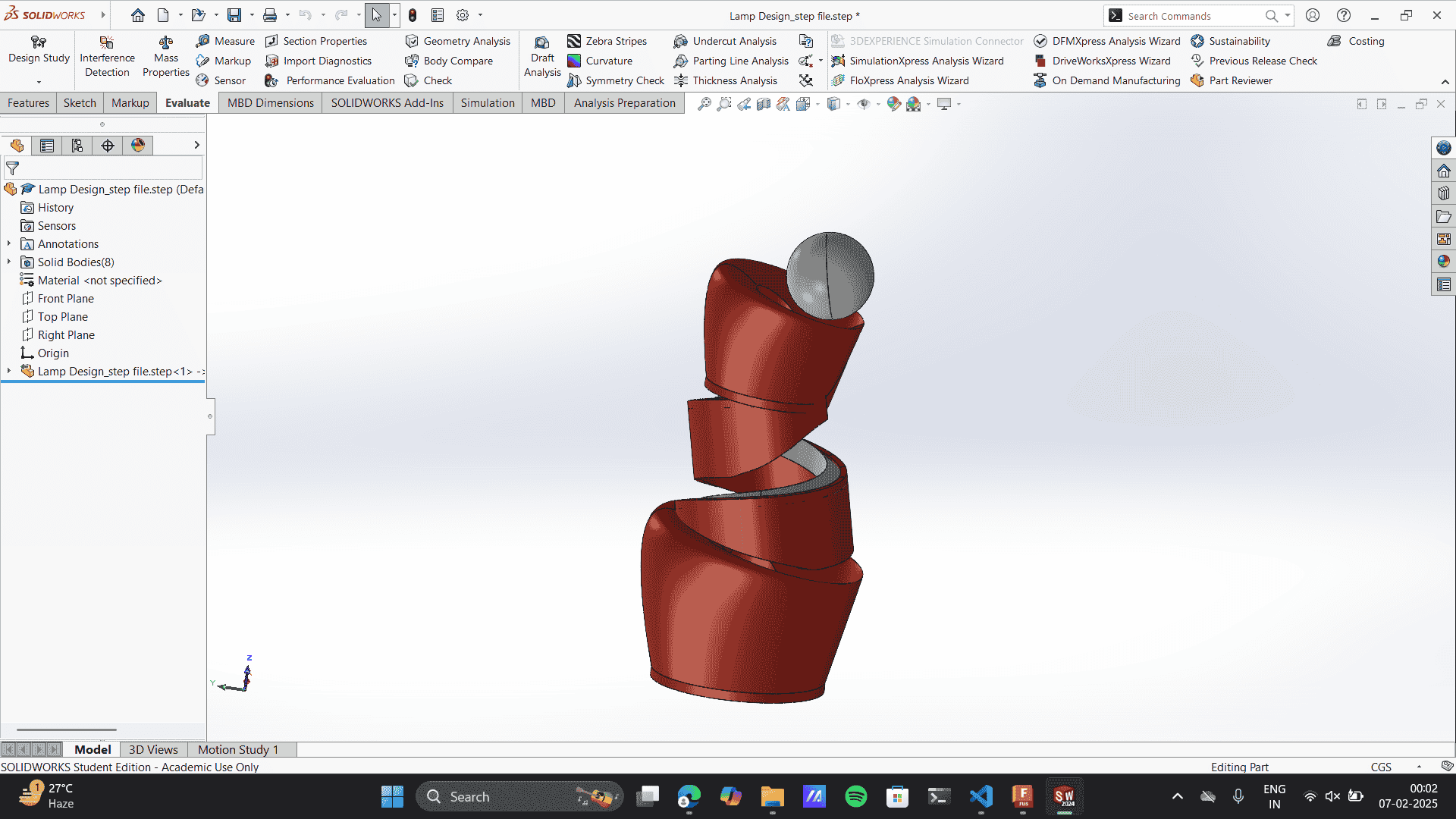
- SolidWorks: A professional 3D CAD software used for mechanical design and engineering. It provides tools for designing parts, assemblies, and creating detailed engineering drawings, often used in product development and manufacturing.
- Blender:is a free and open-source 3D creation software used for modeling, animation, rendering, sculpting, VFX( Visual Effects.), and game development. It supports 2D/3D hybrid design, physics simulations, and scripting (Python) and is widely used in industries like animation, gaming, and architecture.
Exploring each Software: Step by step
INKspace:
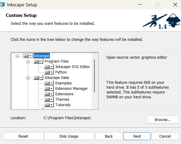
- Software setup: While setting up the software it asked questions like: Browsing for location, and then
Install.
- Opening Document: Opened A prefered documeny and got acquainted to the interface.
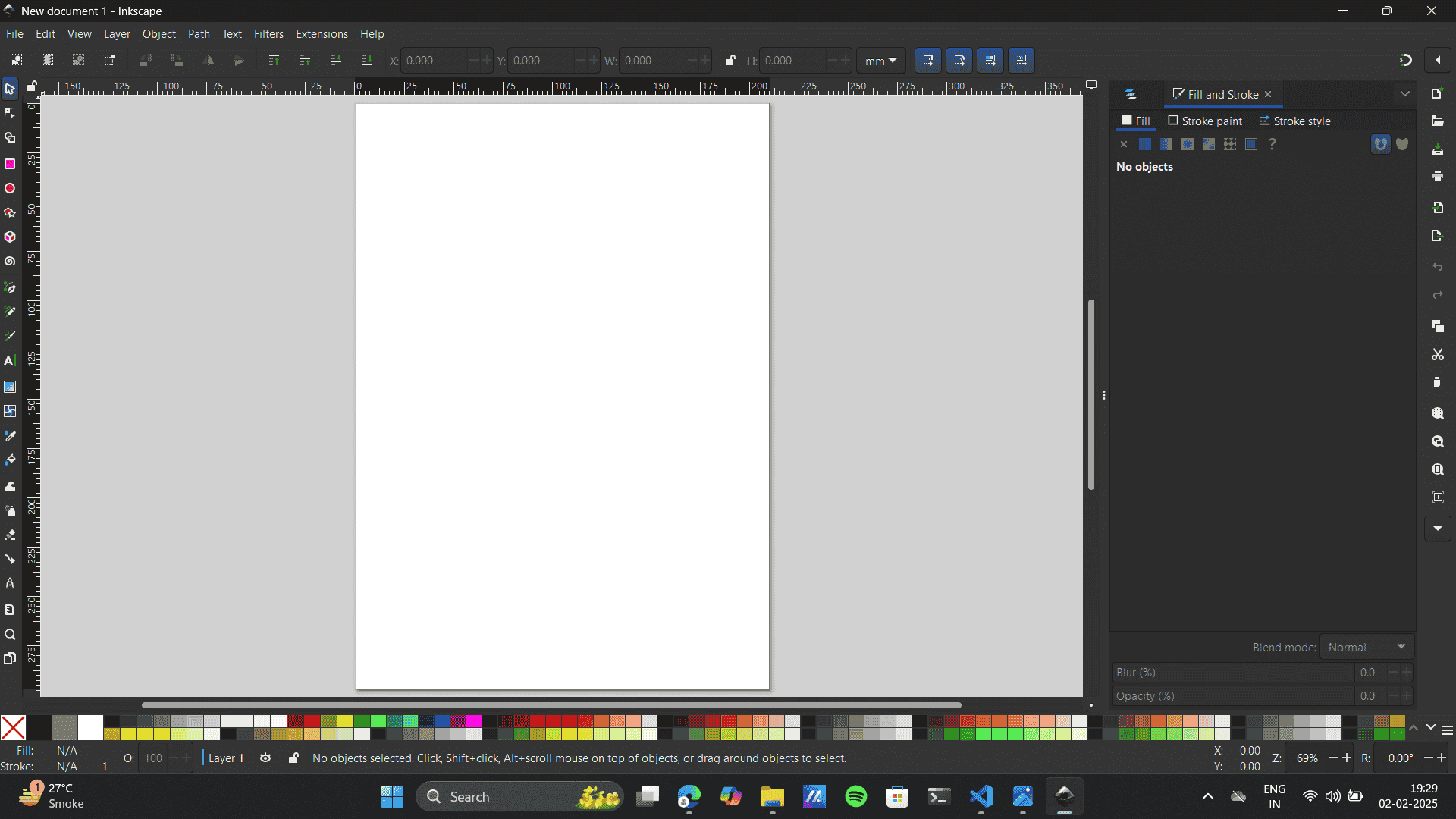
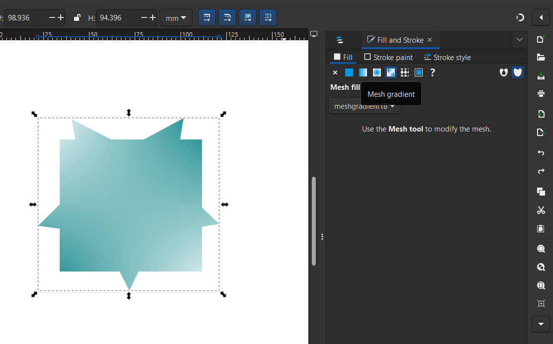
- Exploring Tools: The software being very new to me I explored basic tools like shapes and Gradient.
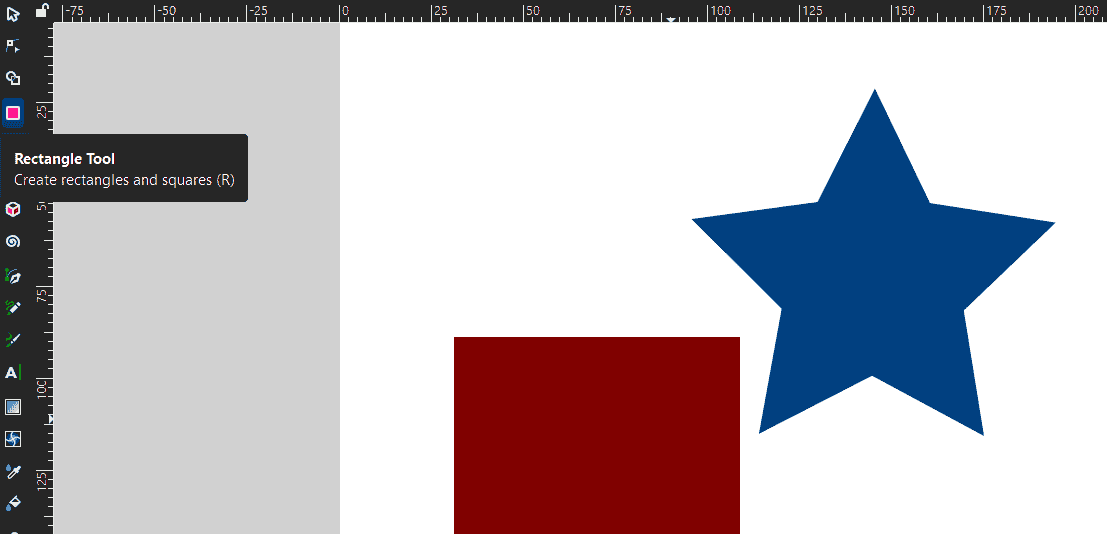
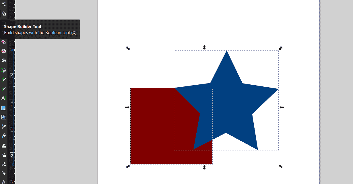
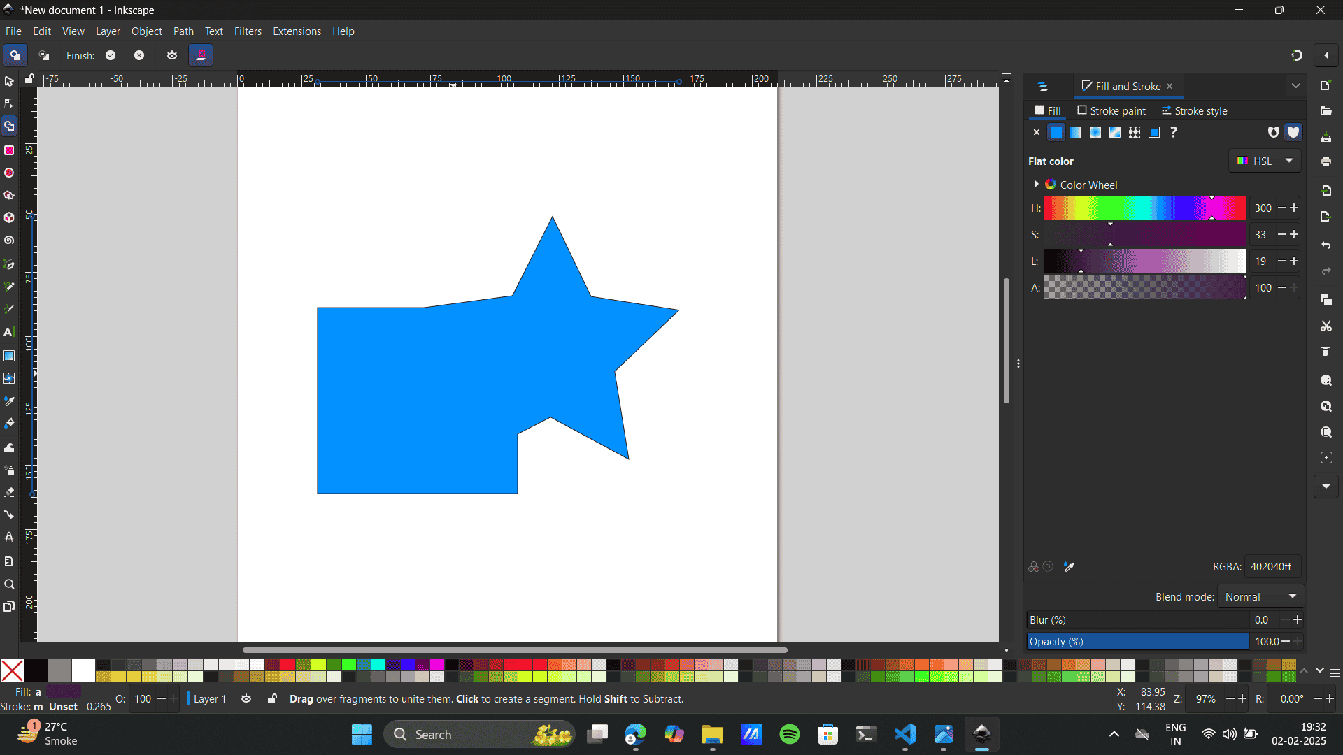
- Shape Builder Is my Favourite tool on illustrator so I explored It here,
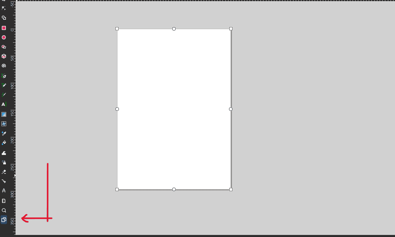
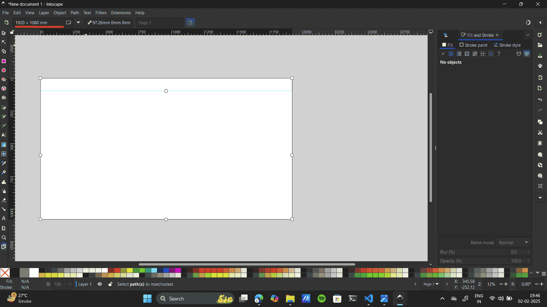
- Further, I wanted to Change the Document size; I had to refer to Youtube change Artboard size on Inkspace.
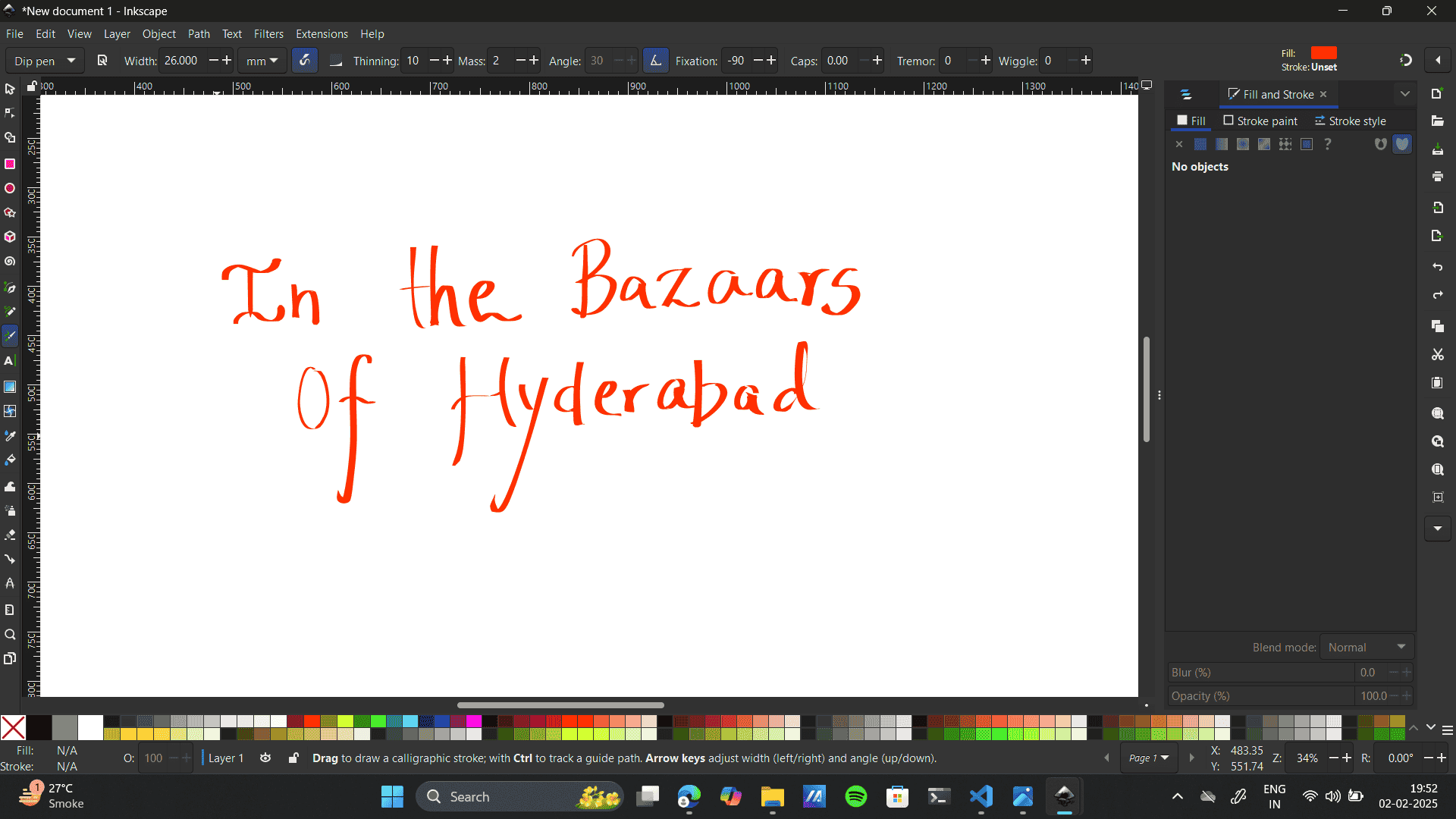
- I did Some more explorations with type.Unlike Illustrator, inkspace create calligraphic, tapered, or pressure-sensitive strokes without using a brush tool.
- Similarly, some explorations on 3d Command and patterns:
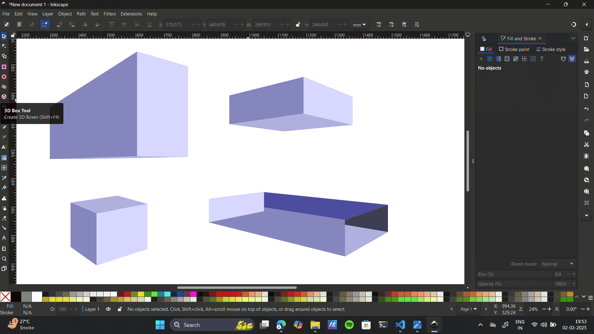
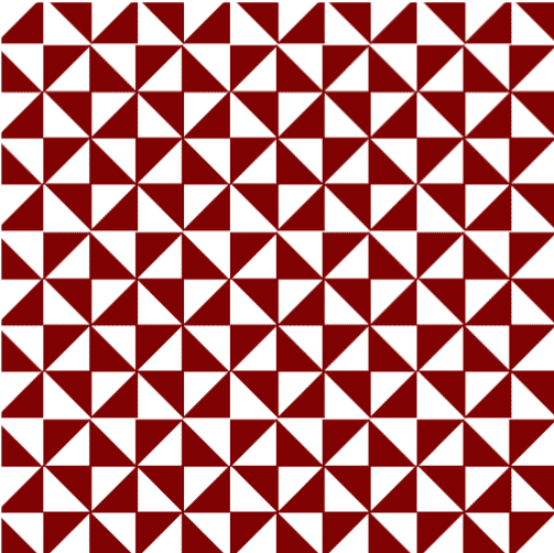
- Exploring creating patterns on INKspace. A step-by-step guide.
Create a Rectangle with the rectangle tool.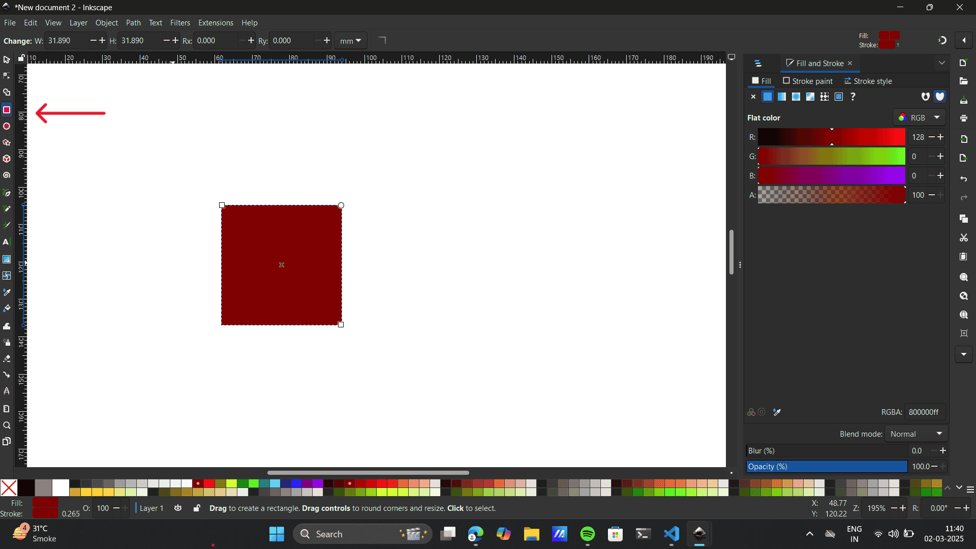 Select the rectangle> Path> Object to path
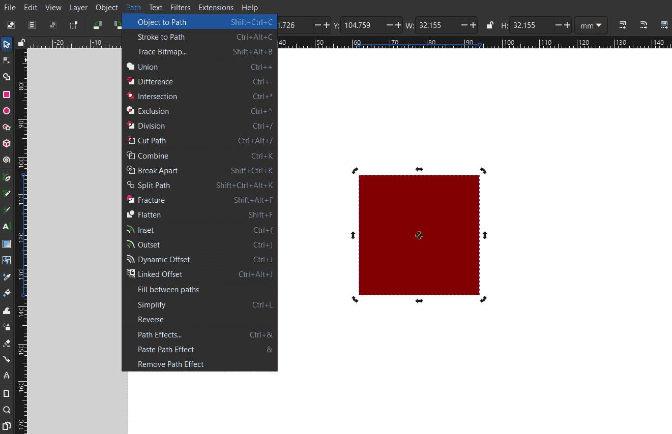 Select the node tool to edit paths by the node.
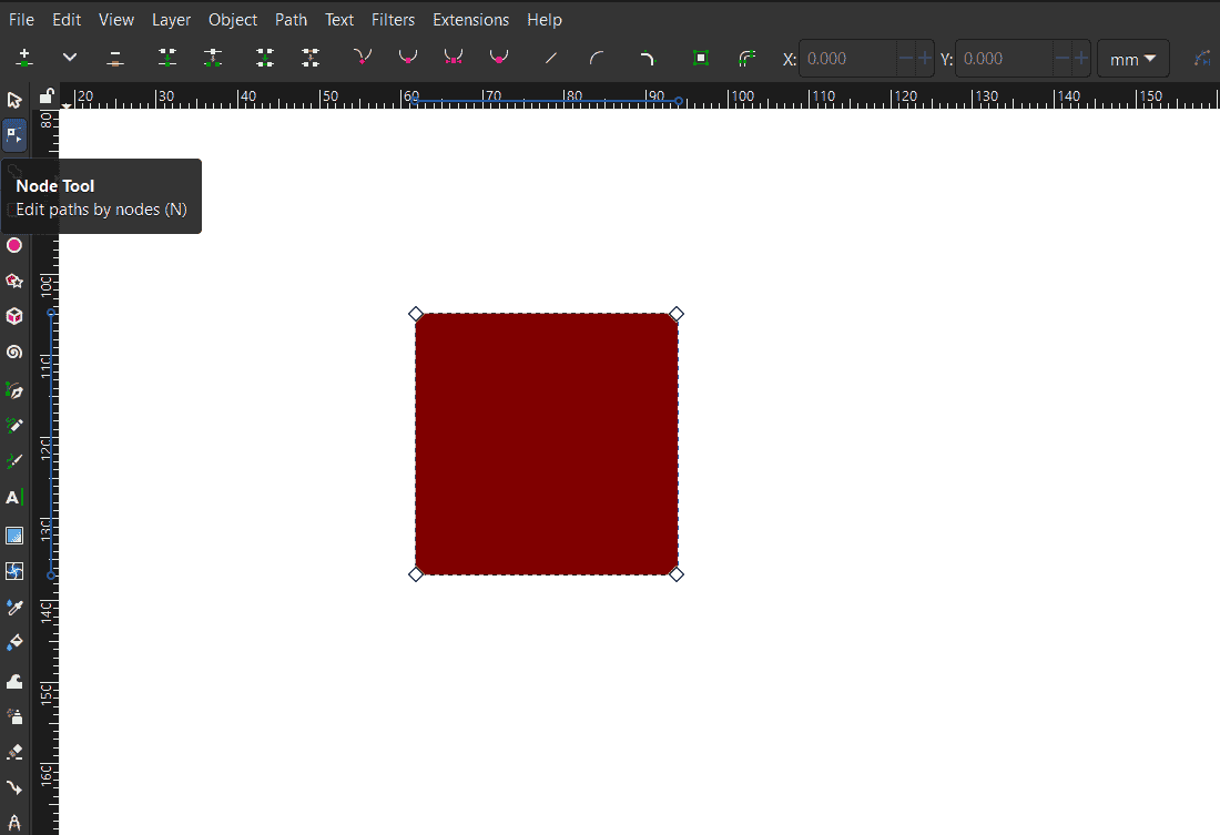 Delete the bottom right node.
.png) Select the triangle> path> paths effects>
Select the triangle> path> paths effects>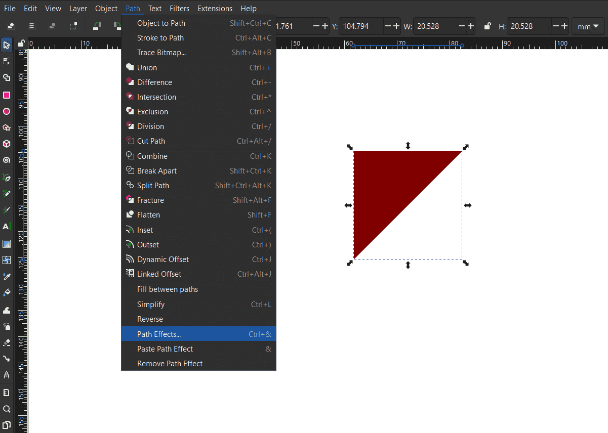 In the path effects> select the tiling tool.
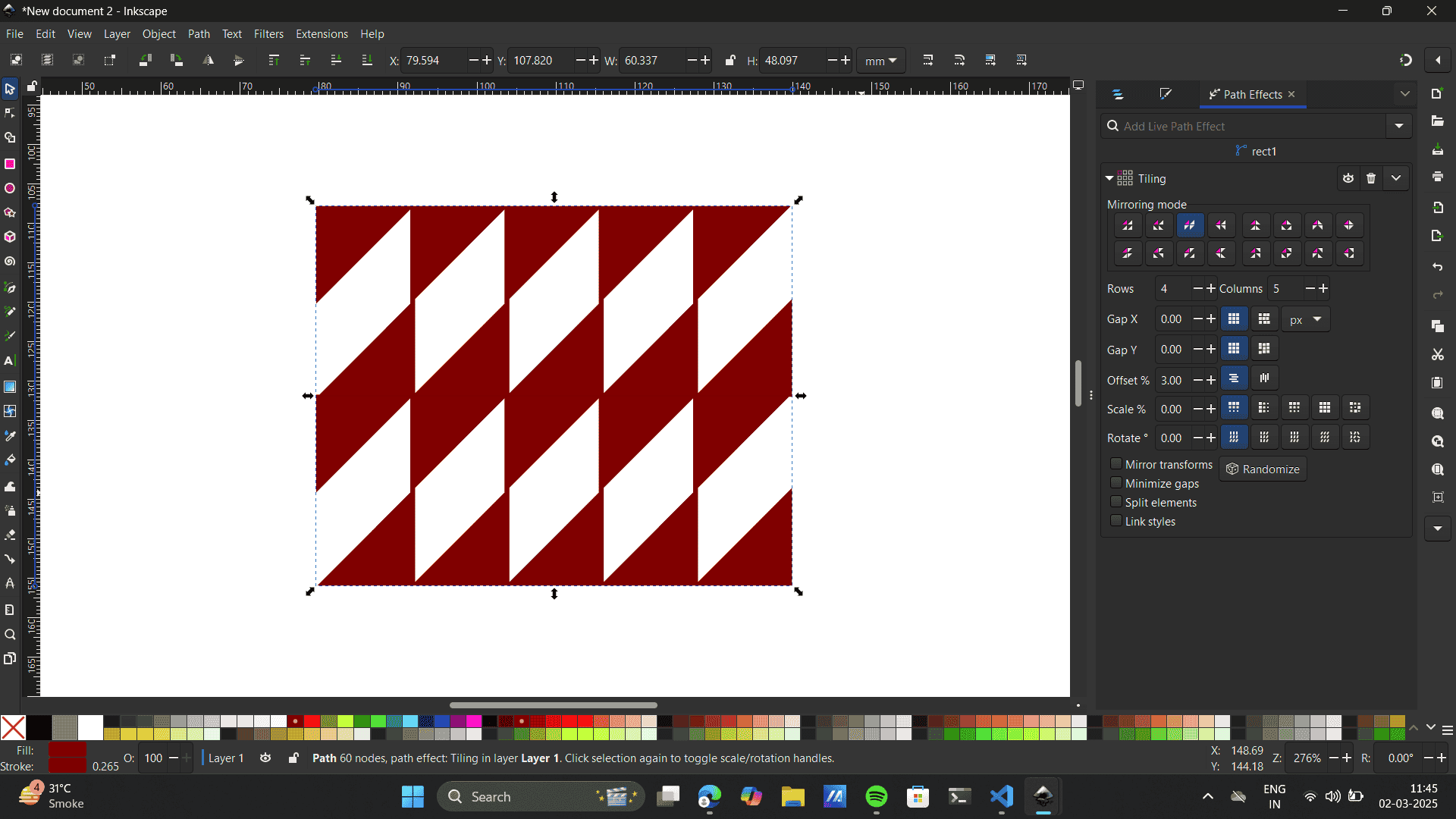
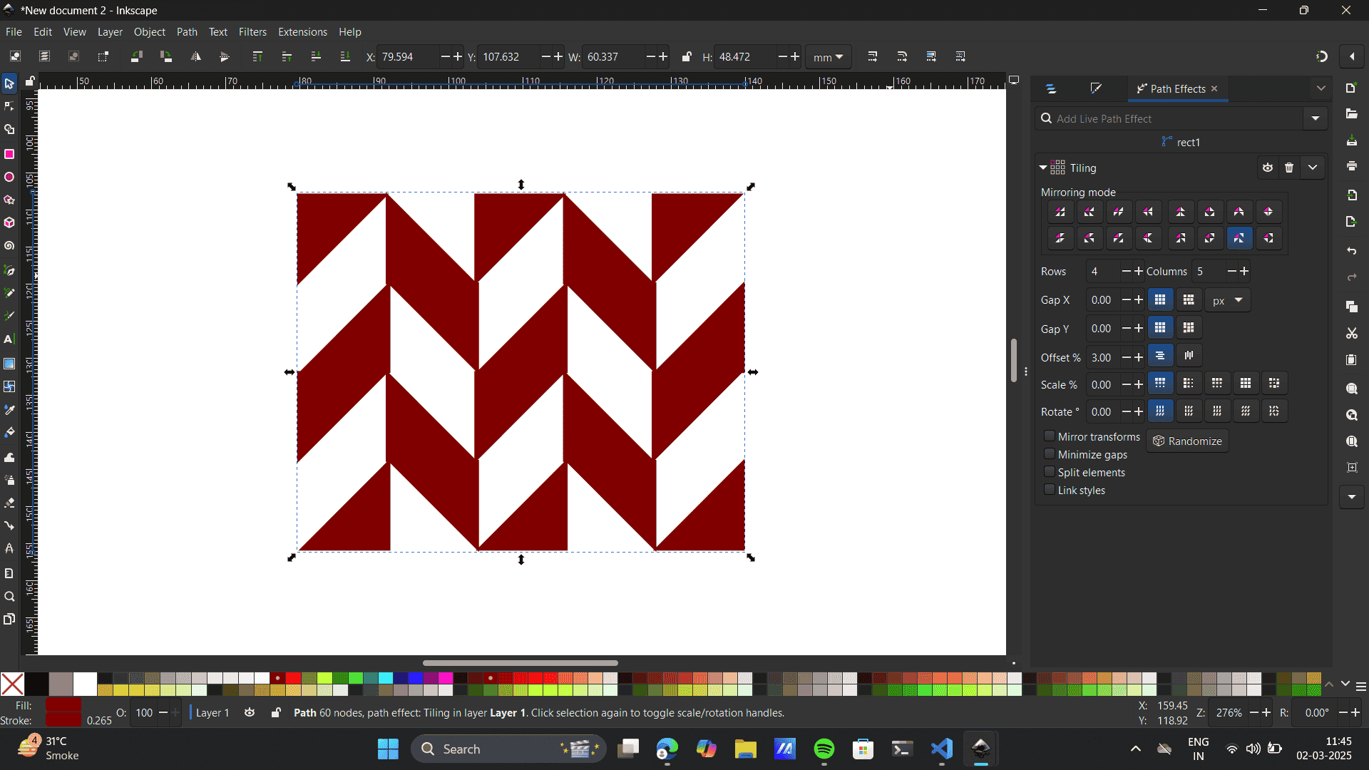
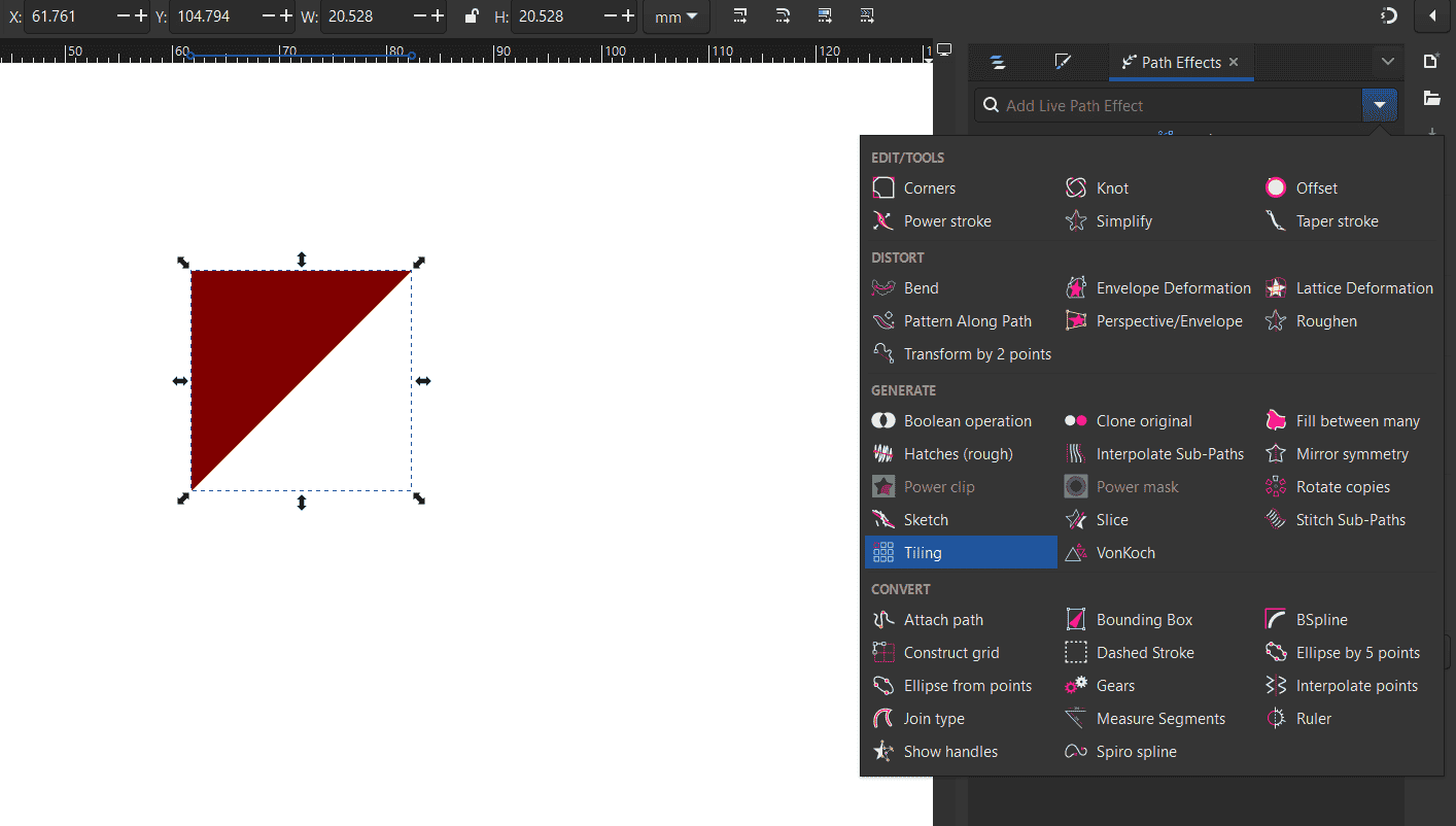 In the tiling feature select the mirror effect.
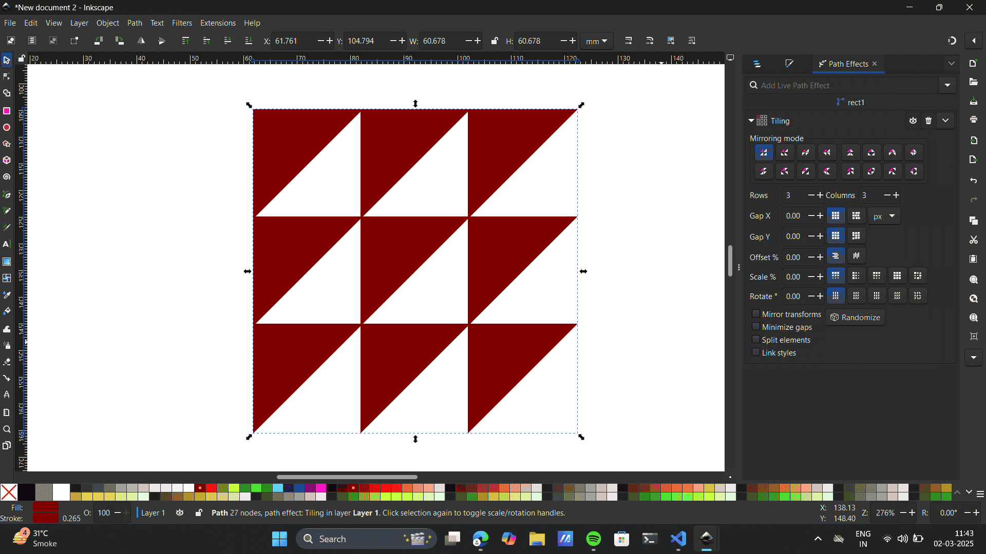 Manipulate rows and columns.
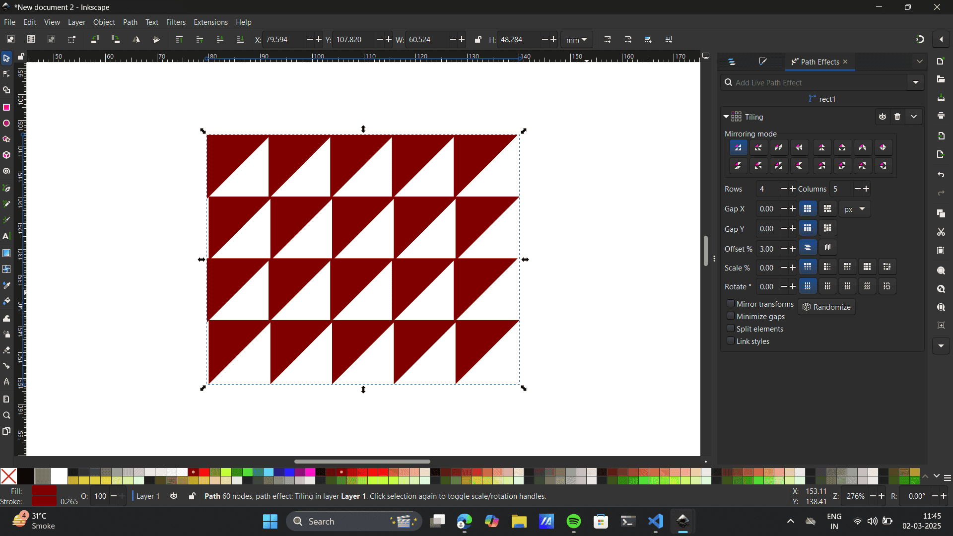
 Select the pattern> Object> Object to pattern
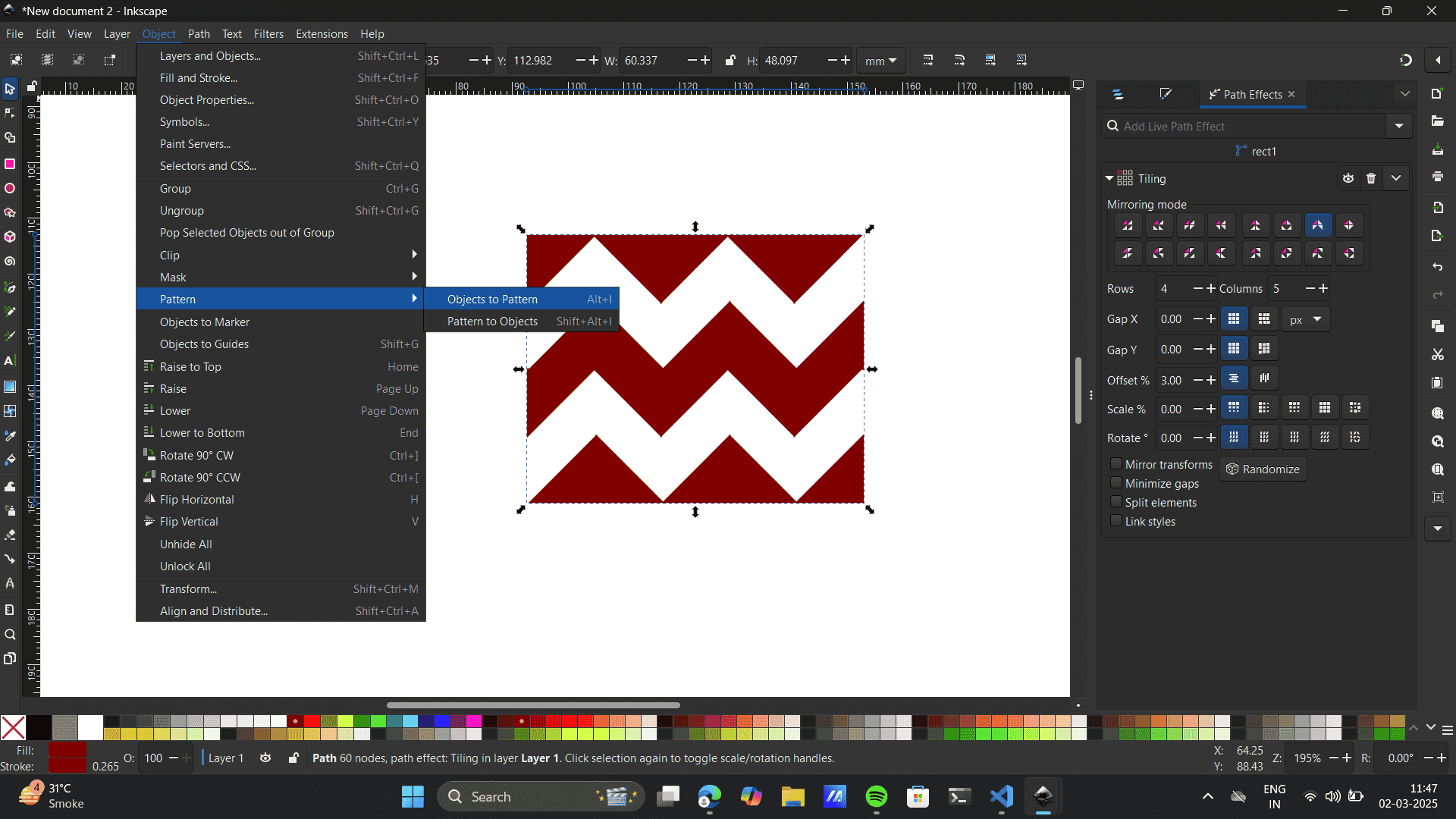 Node tool> select a node> reduce the size of the pattern by clicking cntrl.
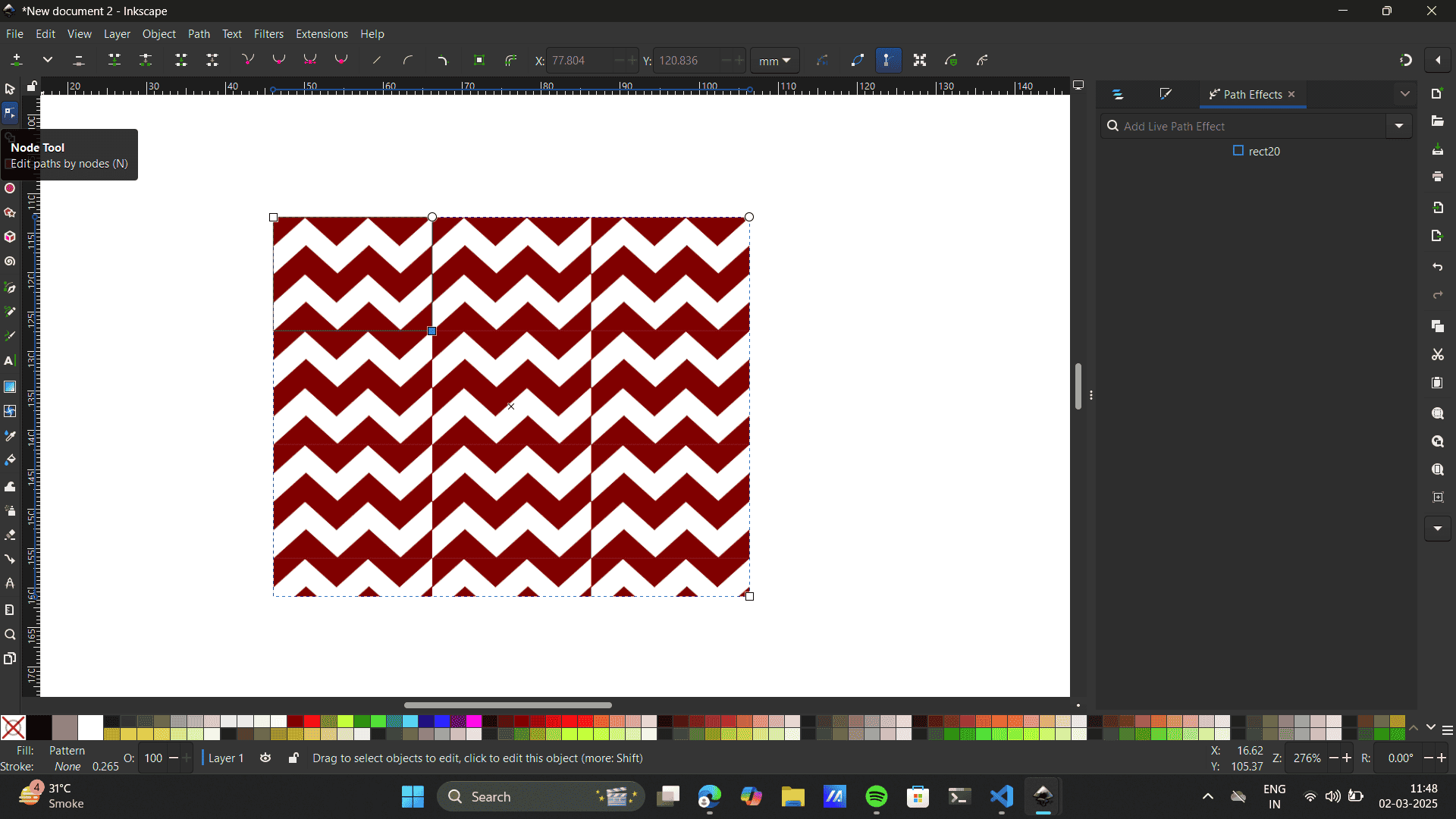
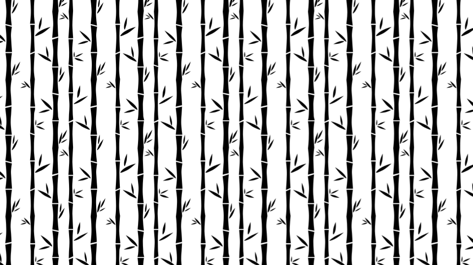
- Final Patterns built.


Illustrator
I have used Illustrator before, It is a go-to for me. I enjoy working on Graphical elements and have worked on various project using the software. You can check my work on Instagram: @abstract_s16 and Behance: samrudhi-rovalekar
-
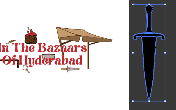
I have a hang of the software so, I made an attempt to
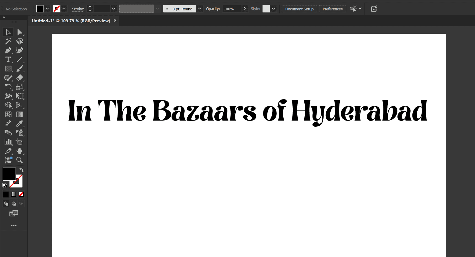
create a title/logo design and explored some fun techniques
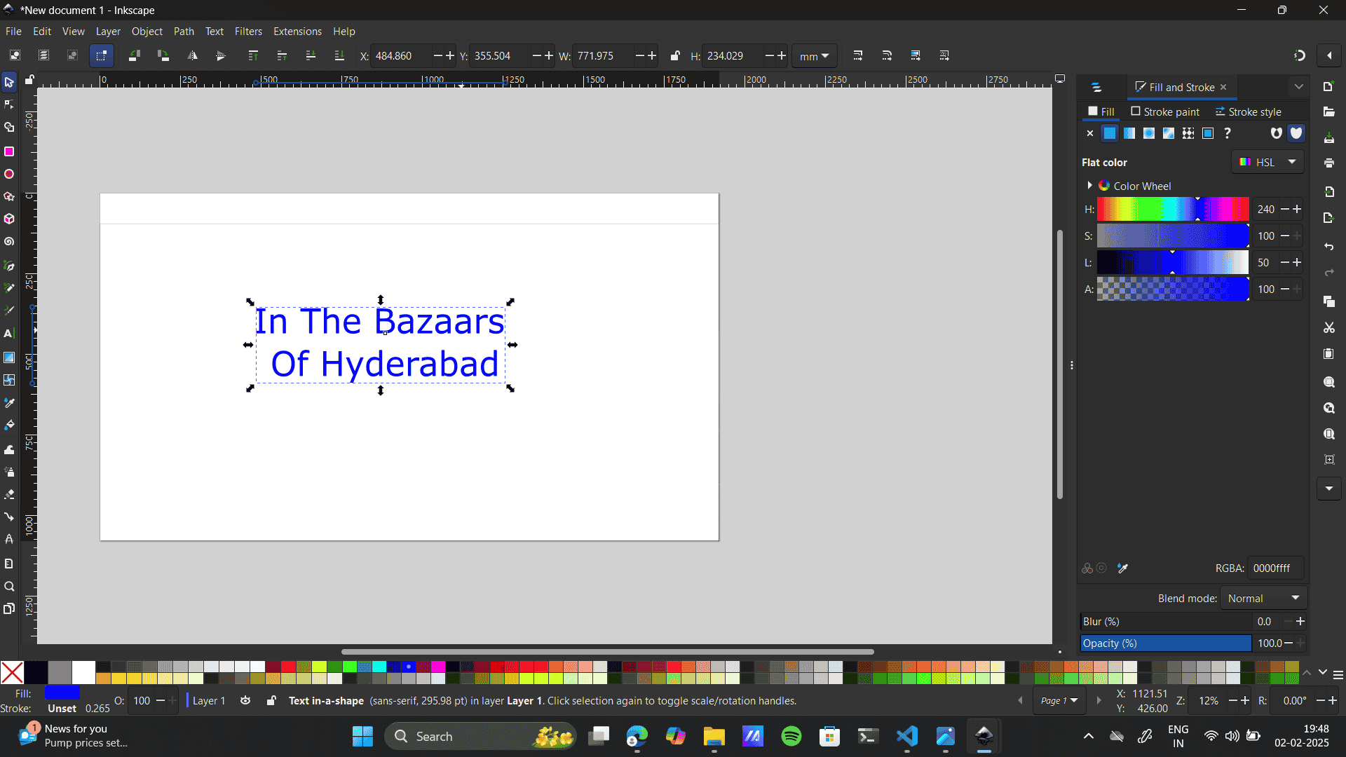
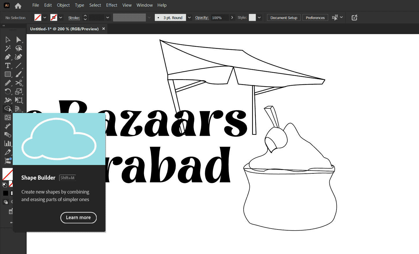
that would complement my Final Project idea: In the Bazaars of Hyderabad by Sarojini Naidu.
I added a text with using the text tool and gave it a font that expressed a dramatic Indian setting.
-
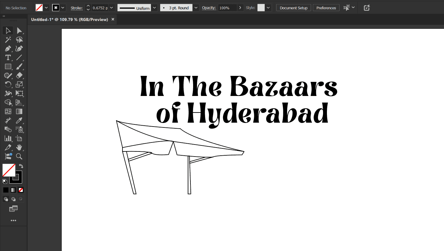
Pen tool: I prefer using the pen to all time. It provides me precision with
coordinates as I join every co-ordinate to the other plus it supports adding curves to a geometric structure
freeflowingly.
Here, I build an Indian stall vector using the pen tool.
 Shape Builder tool: As I mentioned earlier, The shape builder is my all time favourite. I like how multiple
entities
combine or deduct to from one other to give me the desired output. Here, I used the shape builder tool to build
the Masala Gunny Bag.
Shape Builder tool: As I mentioned earlier, The shape builder is my all time favourite. I like how multiple
entities
combine or deduct to from one other to give me the desired output. Here, I used the shape builder tool to build
the Masala Gunny Bag.
-
Exploring All other Tools: I used tools like, circle, brush, swatches etc to get an expressive output.

-
Image Trace: I explored Image trace as it quickly converts raster images into scalable vectors without manual
tracing add
Turns blurry or pixelated images into crisp, editable vector graphics.It simply converts intricate artwork or
sketches
into editable paths.
Click on the image to select it. The image I chose here was a dagger. Image link is here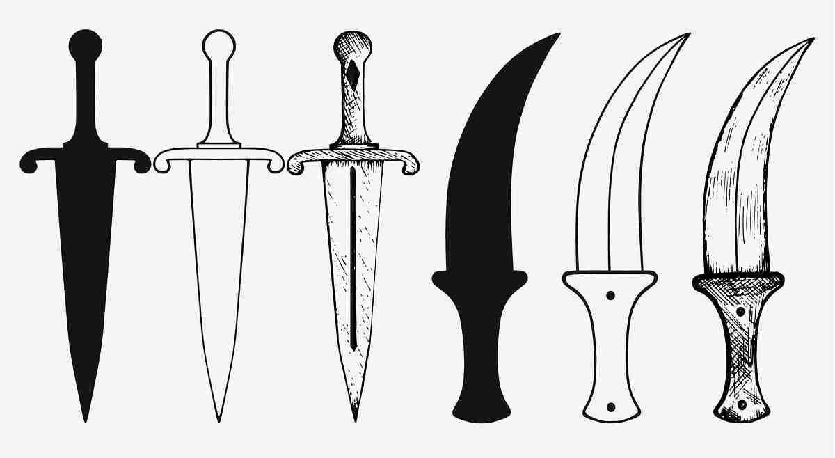
Go to Window > Image Trace to open the Image Trace panel.
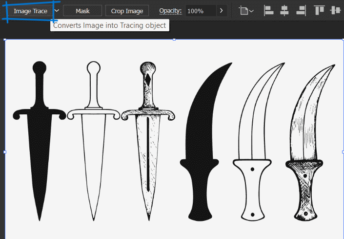
In the Image Trace panel, select a preset from the Preset dropdown (e.g., High Fidelity Photo, Black and White Logo, or Line Art). Here I chose default Bw.
Once satisfied, click Expand on the top toolbar to convert the traced image into editable vector paths.
Ungroup to separate elements and make further modifications.
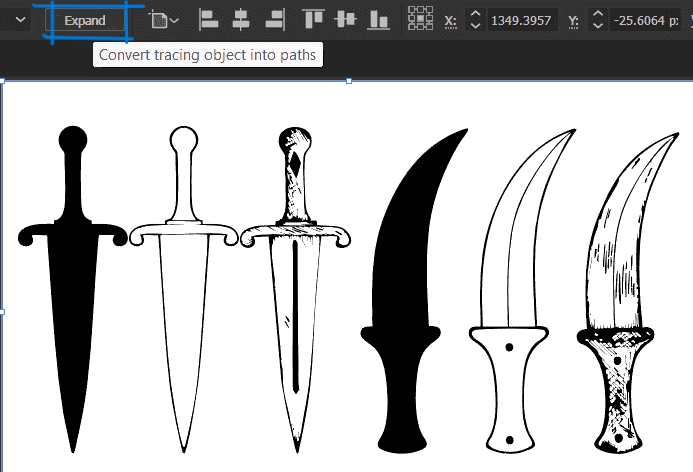
Go to Object > Ungroup to separate elements and make further modifications.
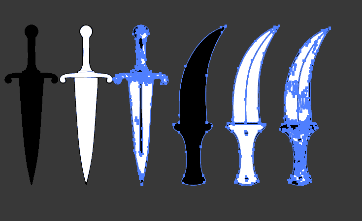
Quickly converted raster images into scalable vectors without manual tracing.
-
Final Outcome:

Gimp
- Gimp is often used for photo editing, creating digital artwork, and manipulating images. GIMP is a popular alternative to Adobe Photoshop. One feature that makes GIMP better than Photoshop is its native support for a wider range of file formats without requiring additional plugins. For example, GIMP can open and export files in formats like XCF, RAW, HEIF, WebP, and DDS more seamlessly than Photoshop, which often requires plugins or external software for certain formats. Additionally, since GIMP is free and open-source, it allows users to modify the software, add custom scripts, and create plugins without needing expensive licenses—something Photoshop doesn't offer.
- Exploring the basics of the software:
-
Basic interface
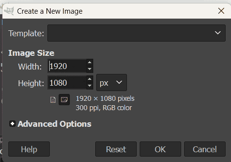
Change document size: File> Document setting> Costum dimensions
Import Image: The following image is reffered to my speculative design project. Watch it on Behance
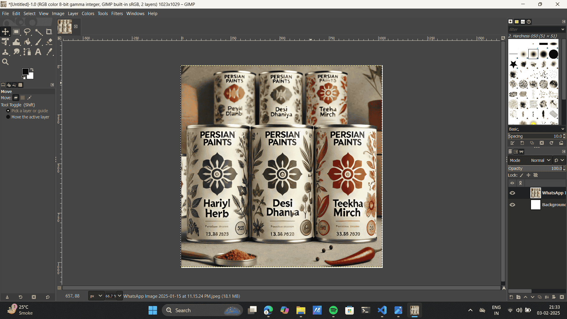
- Using selection tools
Free select tool
Select main layer> Duplicate> delete selected> brush tool to cover the layer.
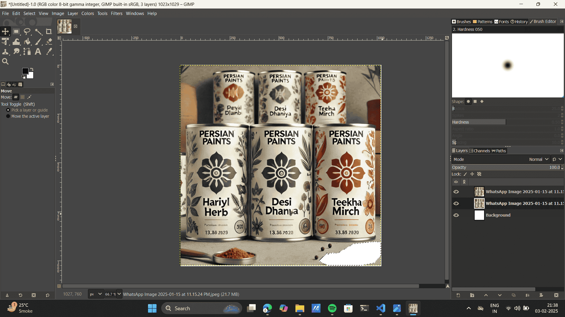
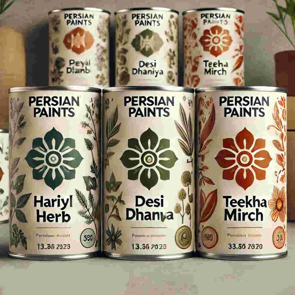
Previous output
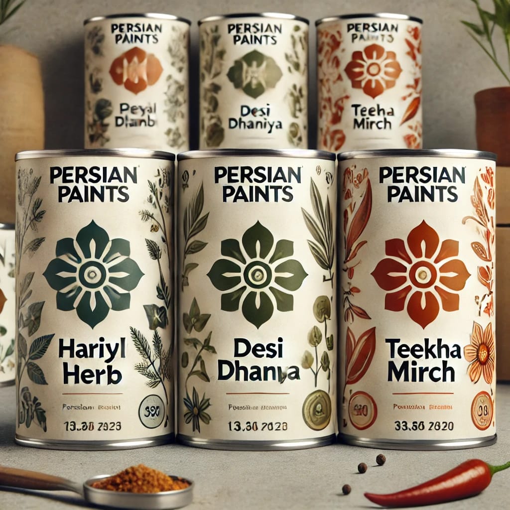
Final Output:
Photoshop
Adobe Photoshop is a powerful raster graphics editing software widely used for image manipulation, digital painting, and graphic design. It offers a comprehensive range of tools, including layer-based editing, selection tools, masks, and advanced color correction, allowing users to create and enhance images with precision. Photoshop is extensively used in industries like photography, advertising, UI/UX design, and digital art. Its capabilities extend beyond basic photo editing to include 3D modeling, animation, and compositing, making it a versatile tool for professionals and creatives alike.
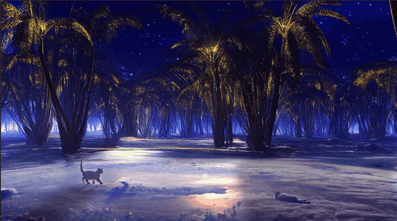
I love the Photoshop’s generative AI features—they it makes creativity feel effortless. Tools like Generative Fill and Expand allow quick edits, letting me add, remove, or extend parts of an image effortlessly. It’s a smart use of AI that doesn’t replace creativity but enhances it. Here is a step by step of documentation of the photoshop AI feature.
Import Image to Photoshop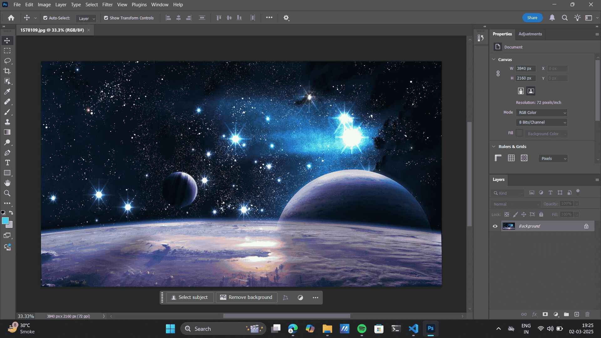 Added the desired prompts to build an phsychic jungle from an Galaxy> Now Export.Use the Lasso tool> select area to add object> Write desired prompt> as in here: cat> Generate
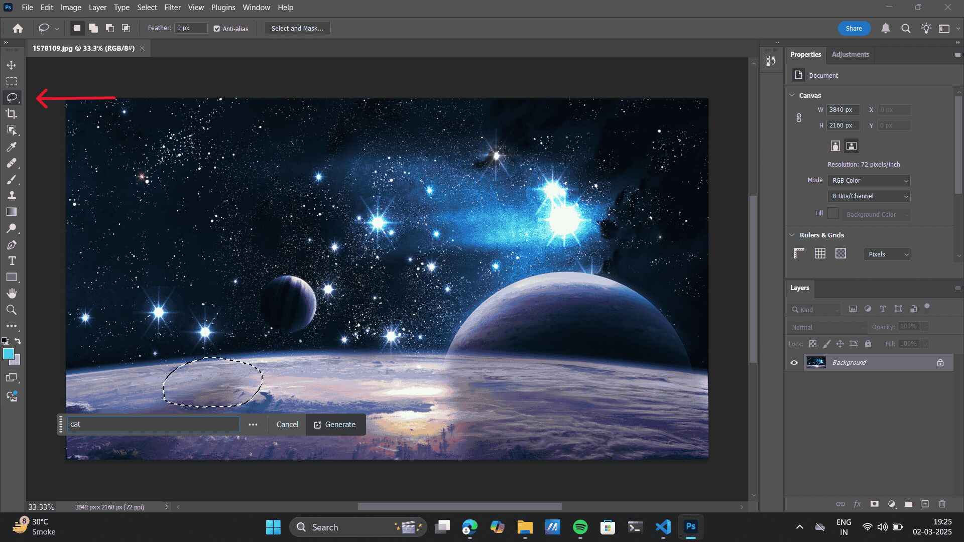 Similarly using the Lasso tool select the background and prompt> as in here: jungle> Generate
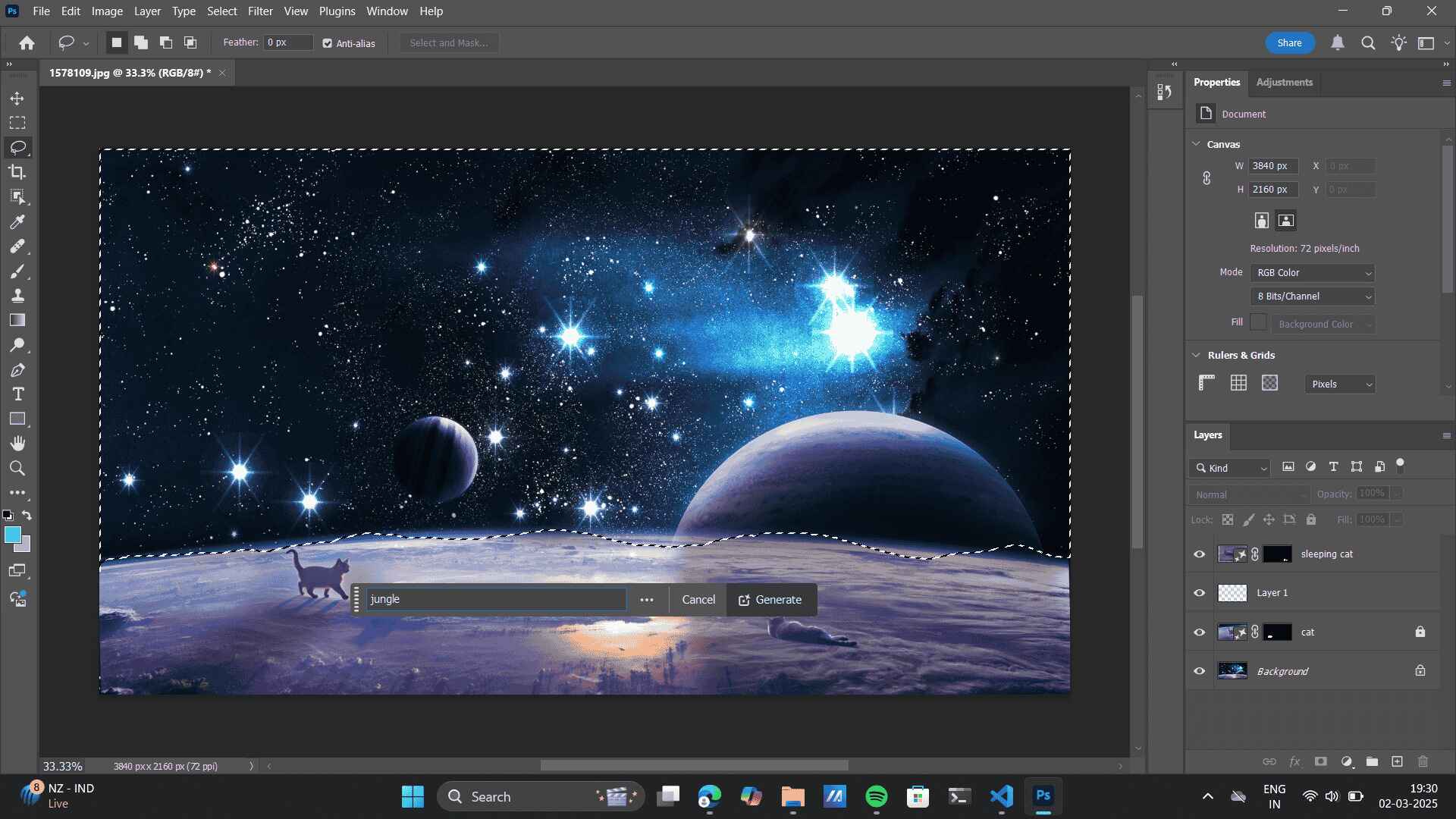
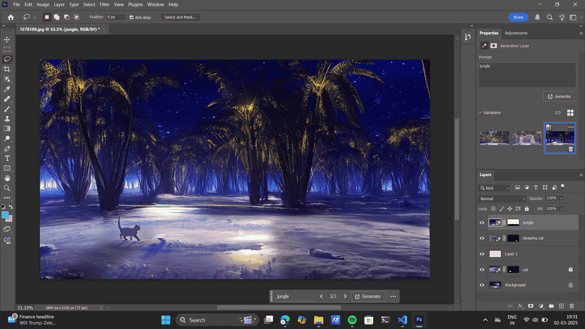 Final Output:
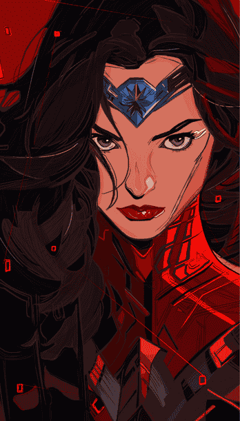
I am quite fimiliar with the Adobe Photoshop, I recently worked on a few projects in Photoshop, exploring various tools like the Brush Tool, photo manipulation, and typography. These projects allowed me to experiment with different design techniques, enhancing my skills in digital editing and creative composition. Refer to my Behance
to learn more about these projects. My mentor for teaching me Adobe Illustrator and Adobe Photoshop is my college proefessor, Shefali Desai. Also, typography was taught to me by Gunjan Kaul.-
Wonder Woman: Brush tool.
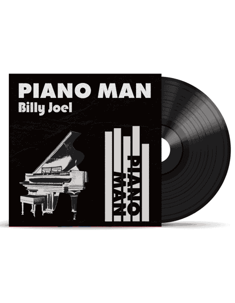
Boat Earphones: Photo manipulation

Typography:
FreeCAD
Freecad was very new for me, I reffered to the Youtube video to get acquainted to the FreeCAD basics to get fimiliar with it’s interface. I tried exploring Spreadsheet-Driven Design in FreeCAD.
FreeCAD allows you to control dimensions and parameters using a spreadsheet, making it easier to modify designs without manually updating each feature. This is especially useful for parametric modeling (where changes in values update the entire model automatically). The software being very new for me i referred to a youtube video to understand Spreadsheet driven design.Step-by-Step Guide: Using Spreadsheets for Parametric Design-
-
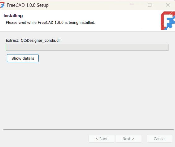
Installing Freecad: It will ask basic information like setting up the browser destination. I clicked 'Next' to
almost all of the set-up questions that the FreeCAD setup asked for the installation process.
-
New File: On opening a new file, FreeCad gave me options for new file types to work one, for eg: Parametric,
assembly etc.
I went furthure with Parametric Part design.
-
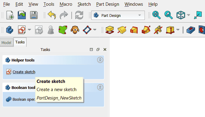
Create Sketch: Once I opened a new file, i went forward with the following steps:
-
3d model using helix
Surface Modeling
Material exploration
-

SolidWorks:
I am currently designing a robotic arm in SolidWorks, and I love how the software helps me assemble each part with precision while delivering concise sketching. I have been creating individual components like joints, links, and actuators using sketching and extrusion, ensuring accurate constraints for smooth movement. The assembly process is particularly exciting, as I can apply mates to simulate real-world articulation and refine the arm’s kinematics. Although the design is still in progress, I am actively exploring ways to optimize pivot points, structural integrity, and material choices. SolidWorks has been invaluable in this process, allowing me to iterate efficiently and fine-tune every detail. As I continue working, I aim to refine motion control and manufacturability to bring my robotic arm closer to completion.
It provides tools for designing parts, assemblies, and creating detailed engineering drawings, often used in product development and manufacturing. I am currently working on robotic arm project using the SolidWorks software; somes of the work in prgress:
-
Robotic Arm test bed:
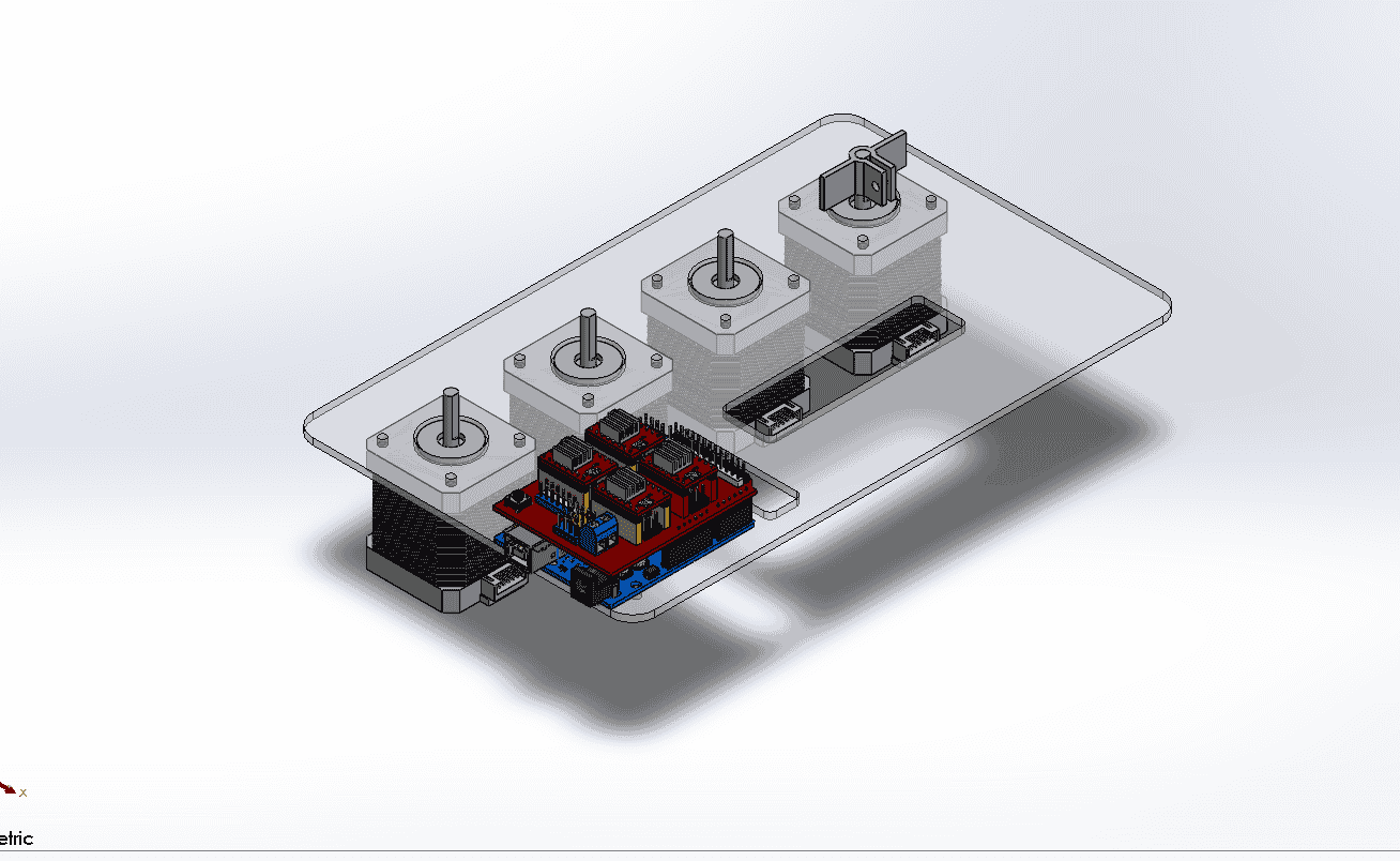
Robotic arm base assembly.
.png)
Robotic arm base exploded view
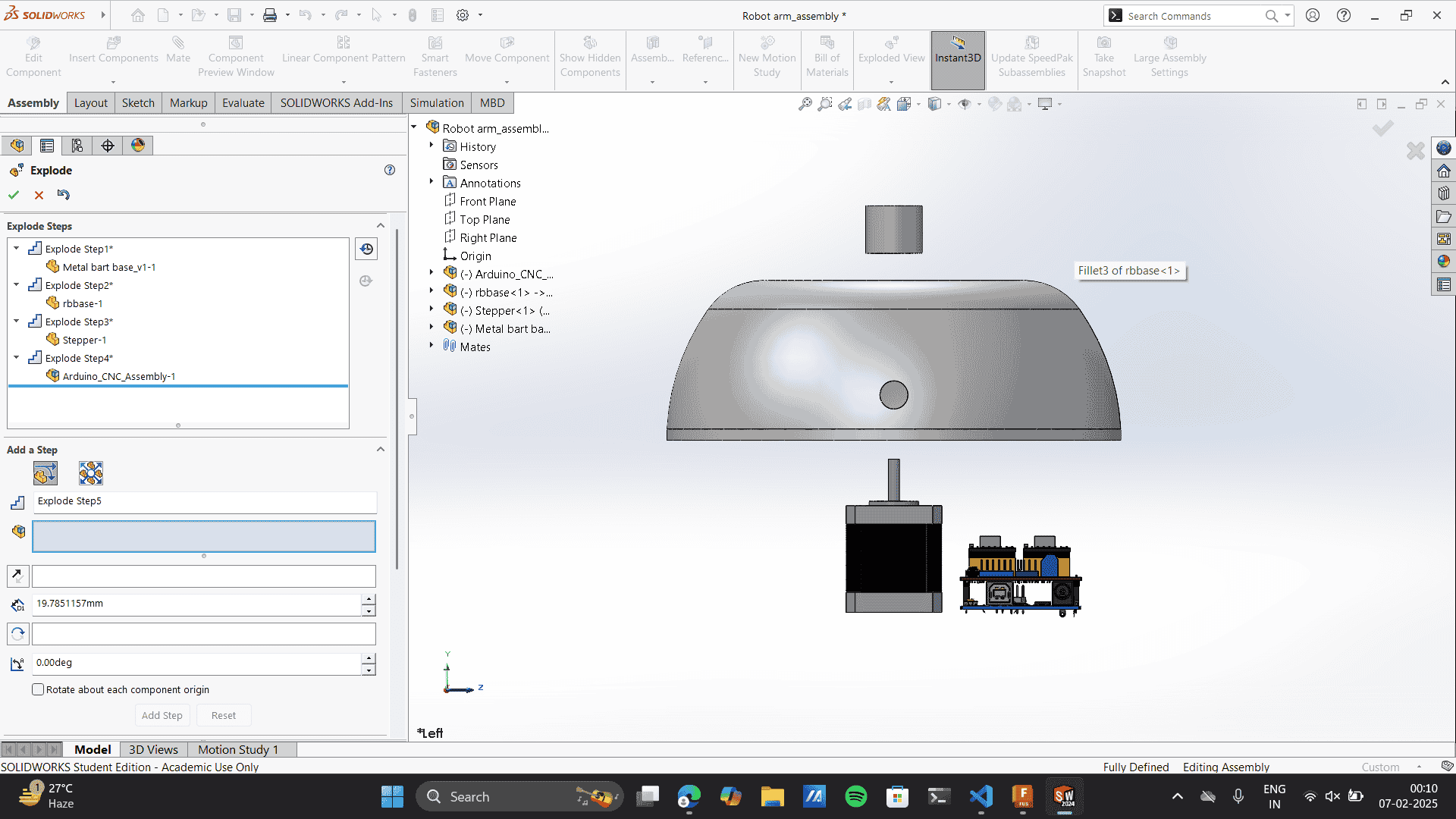
Image and Video Compression
JPEG compression is better than PNG for most applications because it significantly reduces file size using lossy compression, making it ideal for web use and faster loading times. It efficiently handles photographs and gradients, allowing adjustable quality settings to balance size and clarity. Unlike PNG, which retains full detail and supports transparency, JPEG is more practical for sharing images online due to its widespread compatibility and optimized storage.Refer to link for PNG to JPEG convertor, Free Convert.
PNG to JPEG convertor> Choose files> From device/ Drag and drop
.png)
Selected files conversions> Download
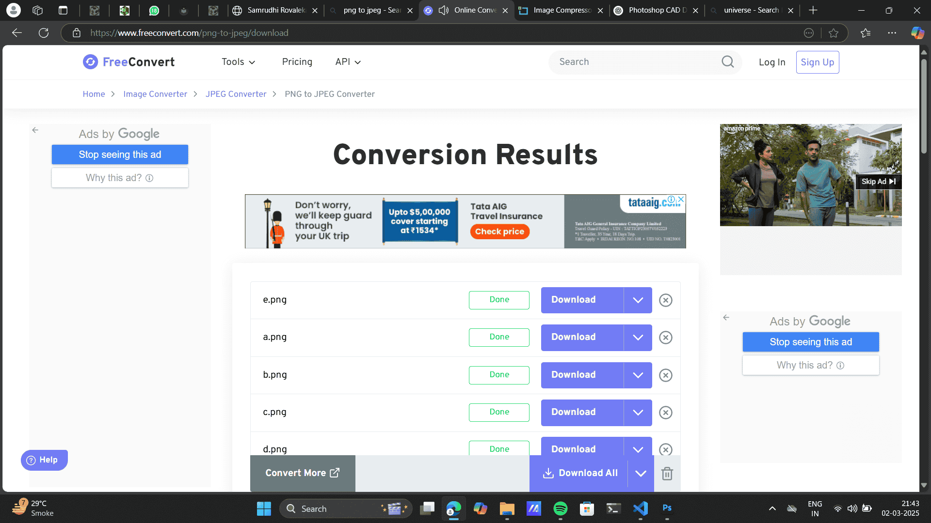
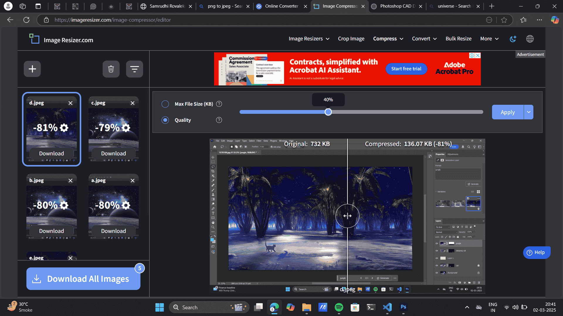
Image and video compression is the process of reducing file size while maintaining an acceptable level of visual quality. It helps optimize storage, transmission, and processing efficiency in various applications like streaming, digital storage, and web content delivery. Refer to this link for image compression: Image Resizer and Refer to link for Video compression, Free Convert.
Choose files> From device/ Drag and drop
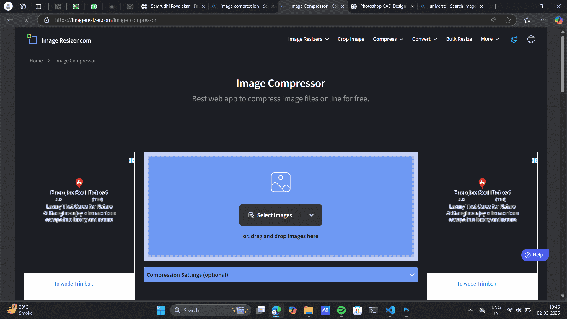
Download Images
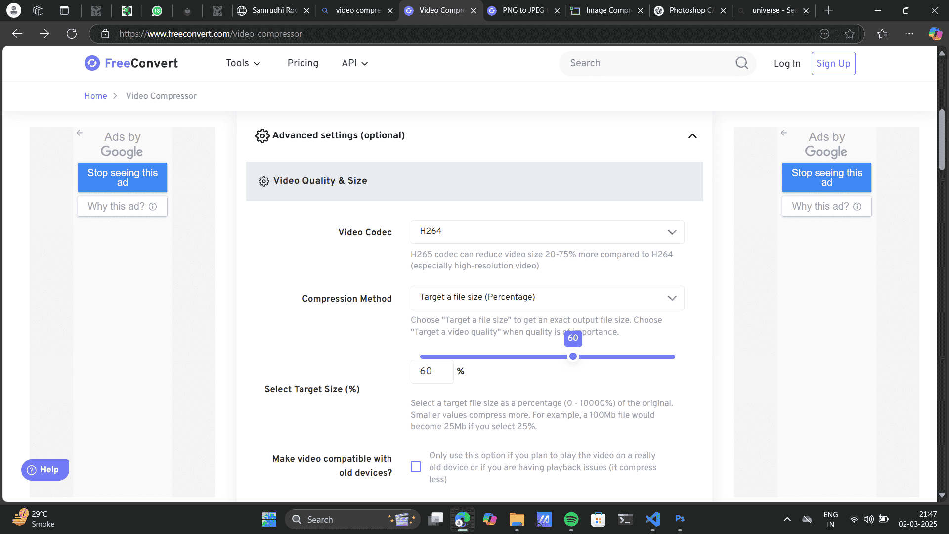
Video Compression
Choose files> From device/ Drag and drop
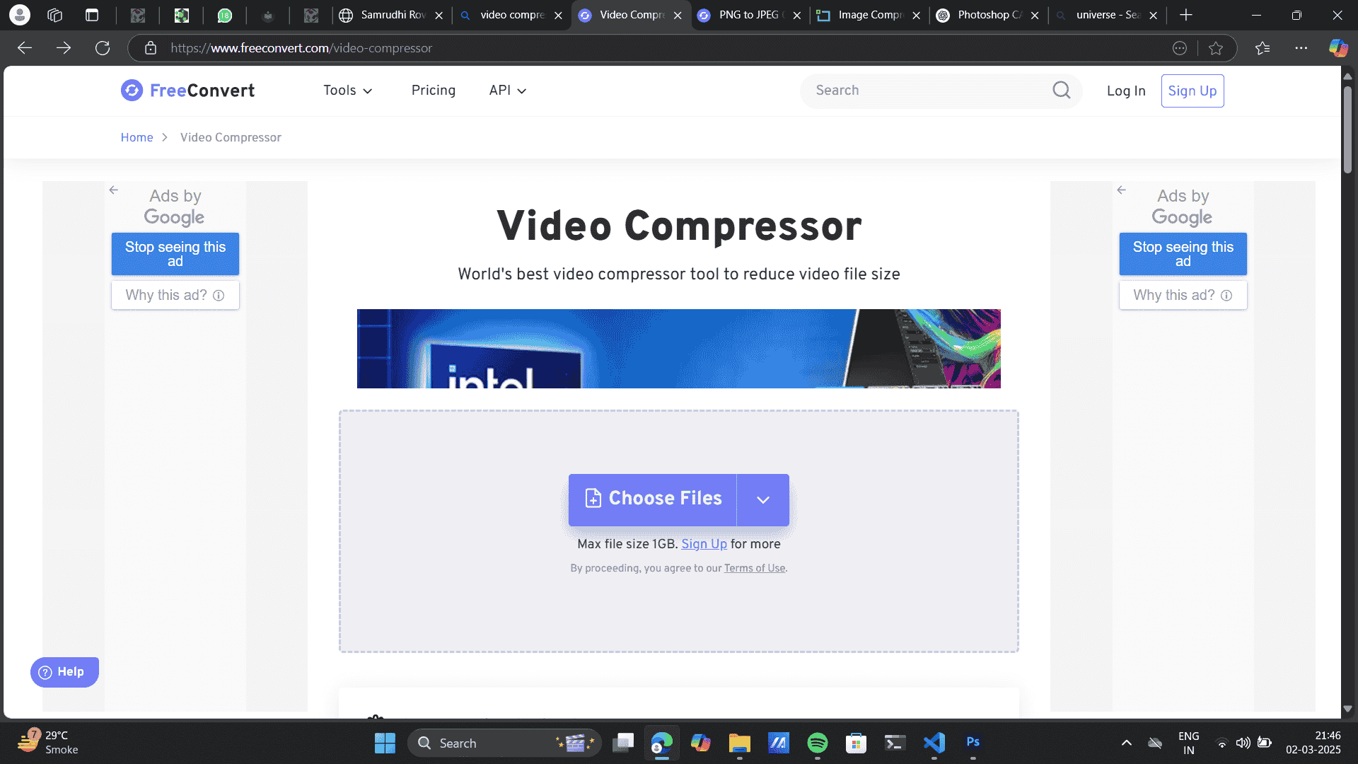
Use the advanced settings for further video compression.
Project files
Download Illustrator Bazaar File
FreeCad Parametric design
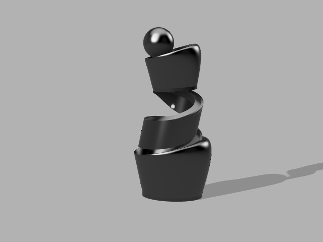
Lamp Design
INKspace pattern svg file
Hero shots
Illustrator

FreeCAD
INKspace
Gimp
Photoshop
Conclusion
Comprehensive Understanding of Digital Formats
- Explored raster vs. vector graphics, 2D vs. 3D modeling, and rendering techniques. Gained insights into resolution-dependent and scalable design methods. Hands-on Experimentation with Software
- Worked with 2D software like Illustrator, Photoshop, GIMP, and Inkscape for vector and raster graphics. Explored CAD software like FreeCAD, Fusion 360, and SolidWorks for parametric and 3D modeling. Understood file format conversions and optimization techniques. Key Learnings from 2D & 3D Software
- Illustrator & Inkscape: Explored shape-building, typography, and vector tools. Photoshop & GIMP: Practiced photo manipulation, selection tools, and layer-based editing. I preferred working on Illustrator and Photoshop because they feel more intuitive and have powerful tools that make designing easier and more efficient. The pen tool, layer controls, and overall workflow are really smooth, which is why I enjoyed using them. That said, GIMP and Inkscape are solid free alternatives—they might not have all the advanced features, but they still get the job done, especially if you're on a budget.
- FreeCAD: Learned spreadsheet-driven parametric modeling for dynamic design adjustments. Fusion 360 & SolidWorks: Experimented with 3D modeling, rendering, material application, and assembly design. Application in Final Project. I prefer Fusion 360 as a design student because it offers a balance of intuitive modeling, rendering, and easy collaboration. SolidWorks, on the other hand, feels more suited for an engineering workflow with its precise constraints and professional-level assembly tools. FreeCAD was interesting to work with, especially for parametric modeling, and I’d love to explore it more.
- Equipped with a strong foundation in digital design and modeling. Can efficiently create, optimize, and document 3D models for rendering and fabrication. I am ready to integrate these skills into the final project by refining models, applying realistic materials, and optimizing files for sharing. Future Improvements
-
-
Create Body:
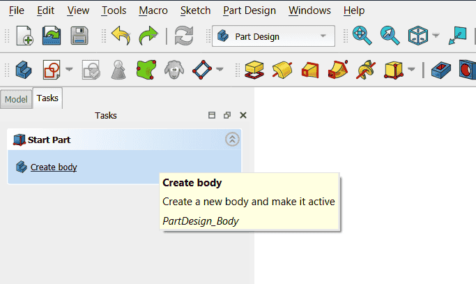
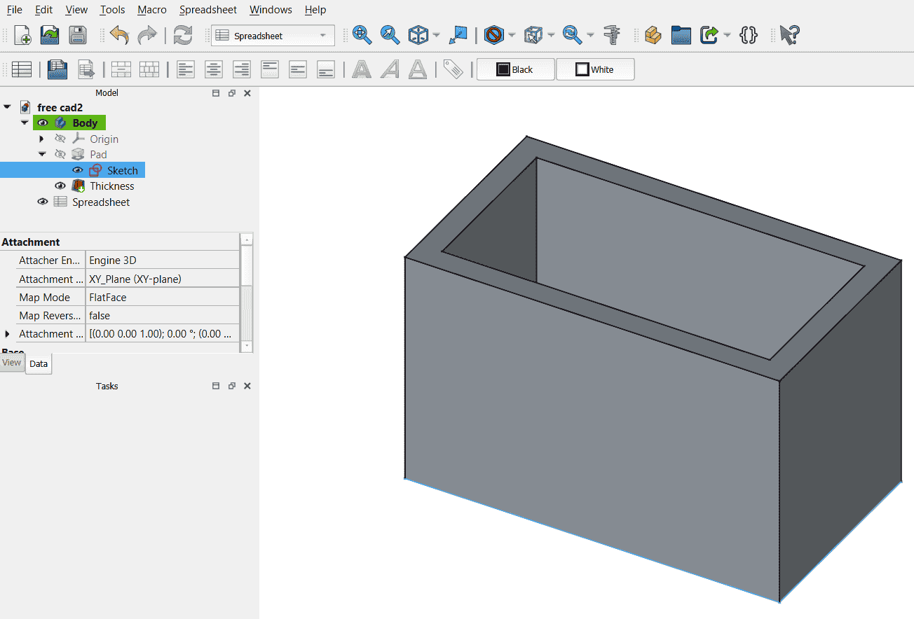
Create sketch:
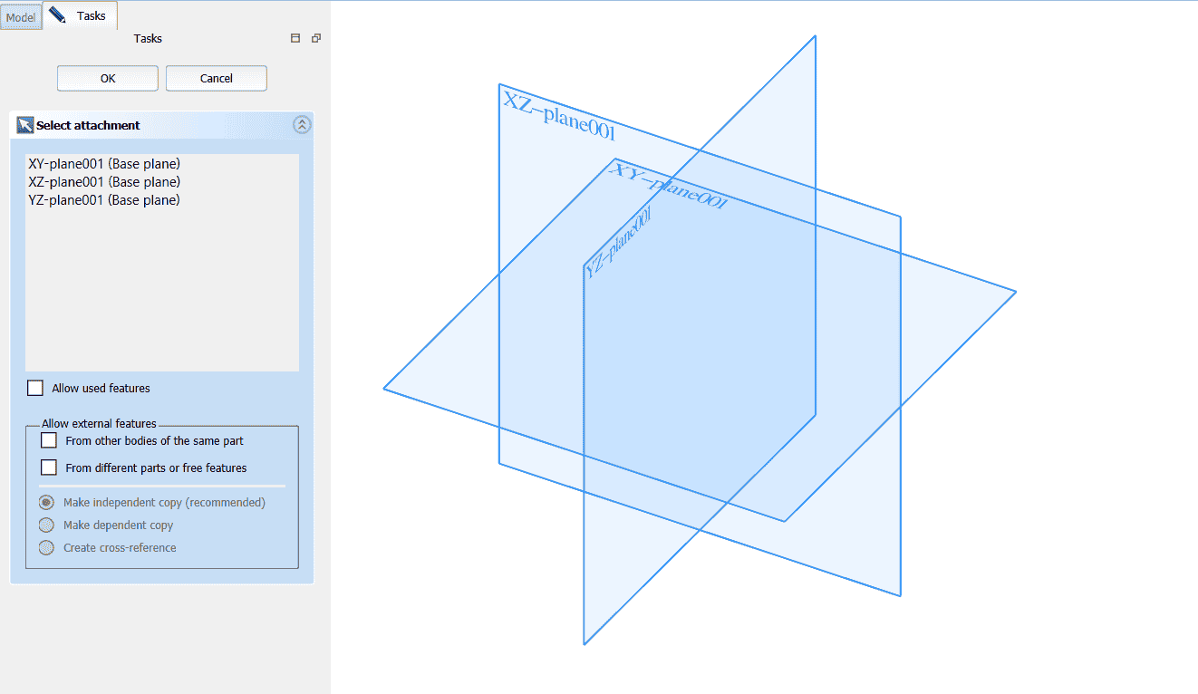
Choose X-Y plane as per requirement:
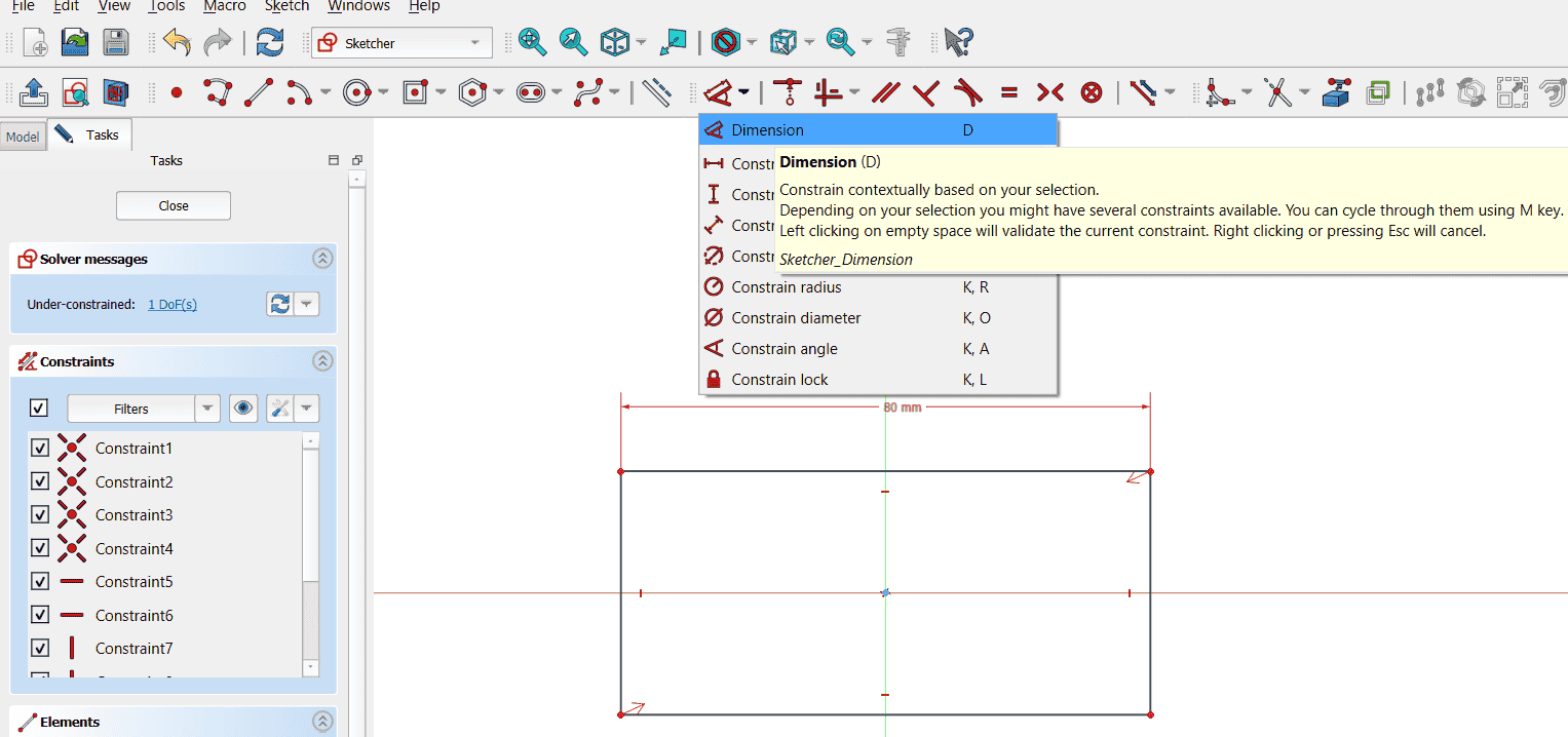
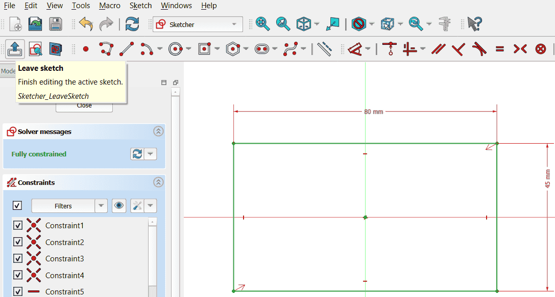
4. I used a centre rectangle tool to build a rectangle, gave it dimensions untill it was fully constrained.Create centre rectangle:
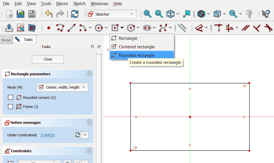
Add constrain:
 5. Padding: Pad in FreeCAD is equivalent to Extrude, meaning it adds thickness to a 2D sketch to create a 3D solid.
Leave sketch when fully constrain:
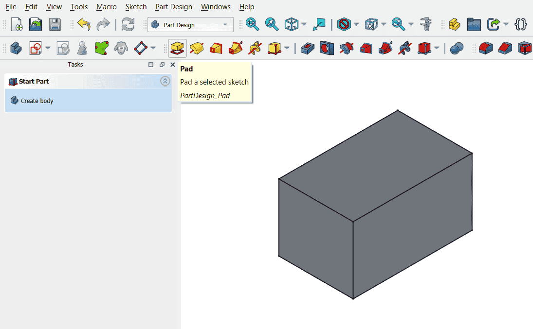
Select the Sketch from the model tree and Click Pad (Extrude)> Length of padding.
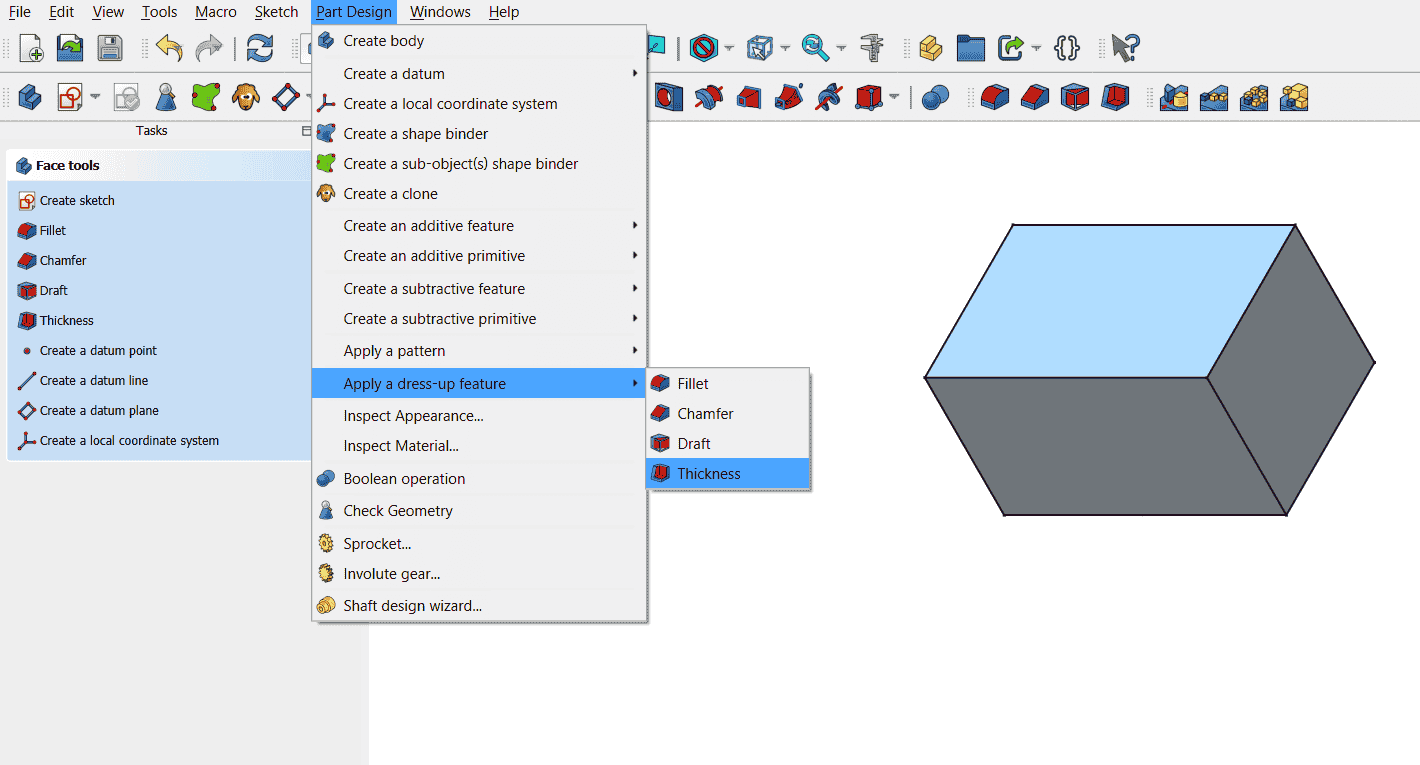
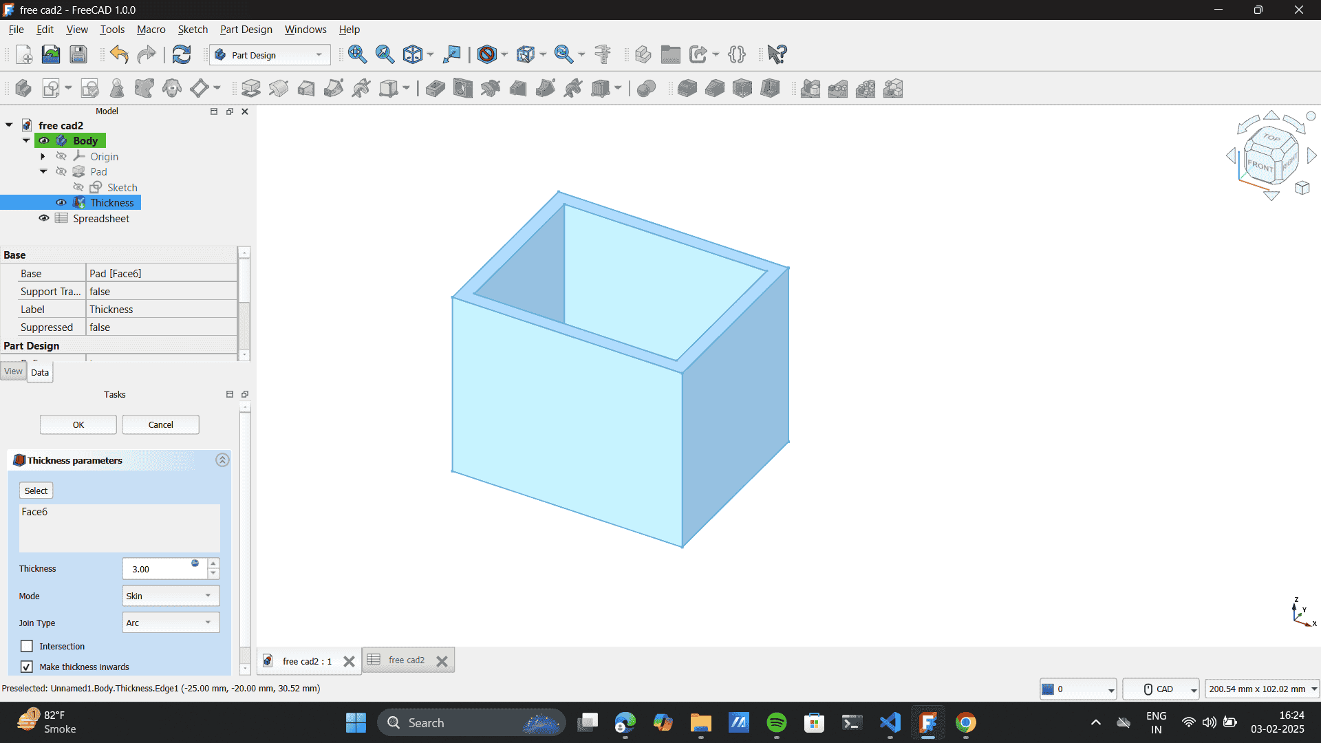
 6. Spreadsheet: Pad in FreeCAD is equivalent to Extrude, meaning it adds thickness to a 2D sketch to create a 3D solid.
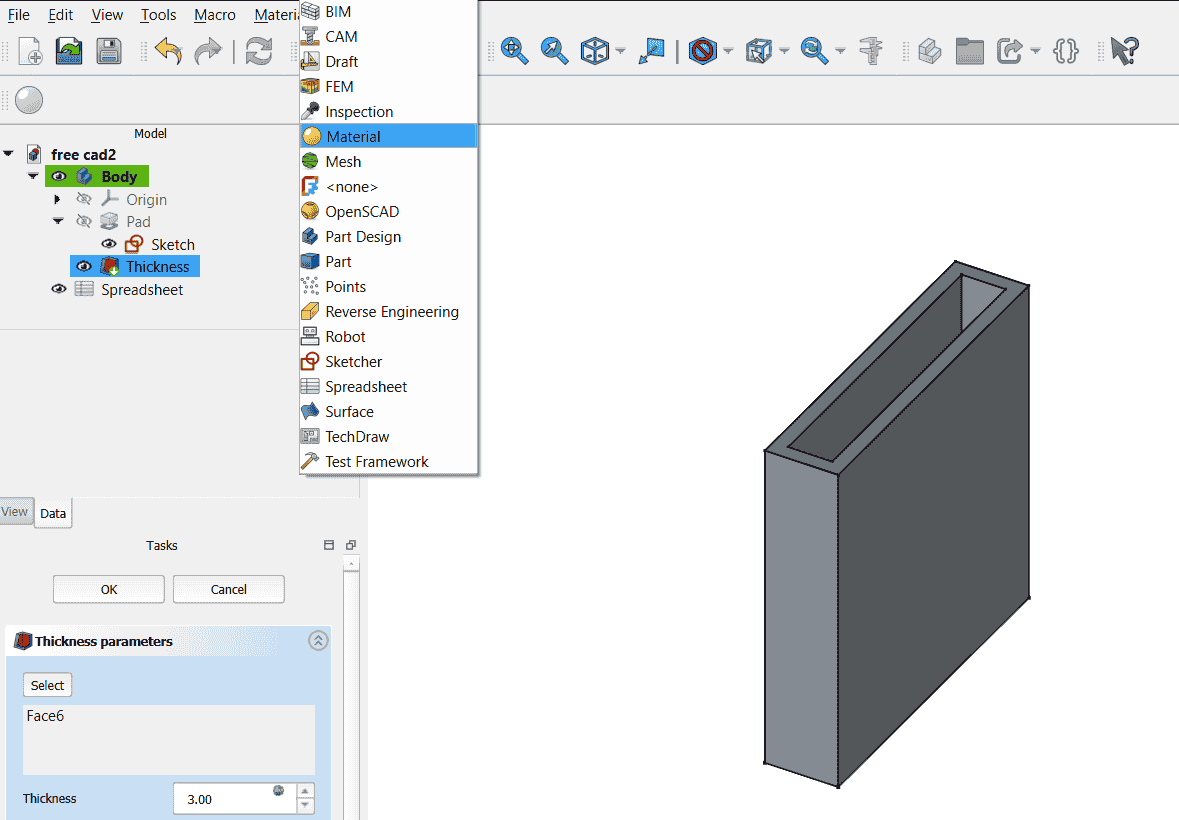
Add thickness by selecting a plane by select plane> part design> add dress-up feature> thickness> thickness amount.
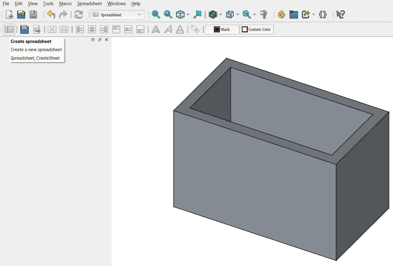
Switch to the Spreadsheet Workbench from the workbench dropdown.
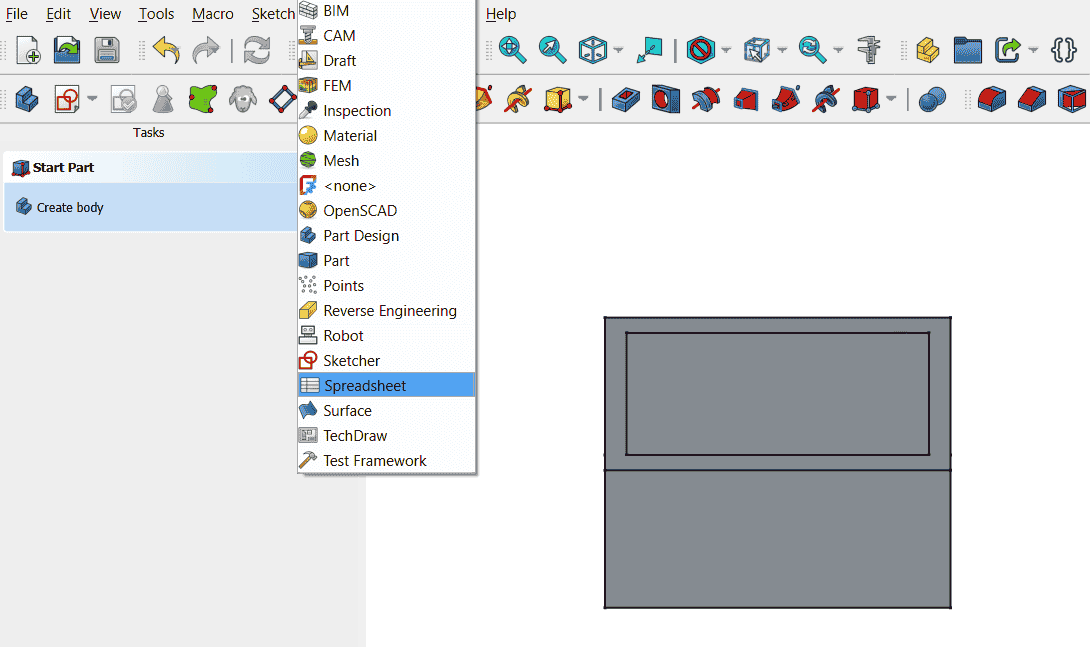
Click Create New Spreadsheet (📄 icon in the toolbar).
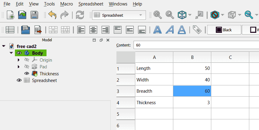
 7. Define values in the Spreadsheet.
Rename it to something meaningful(Parameters) + define Length, breadth, width, thickness
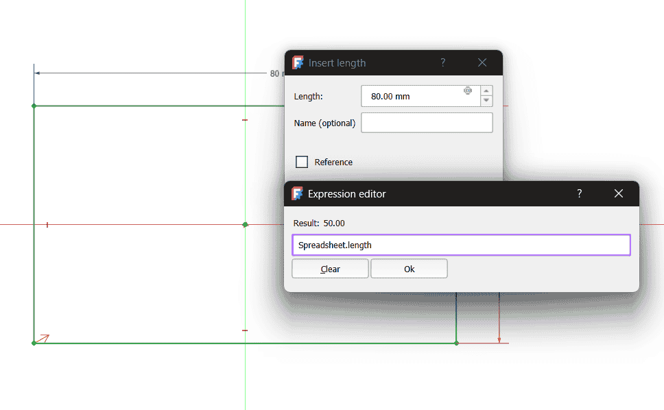
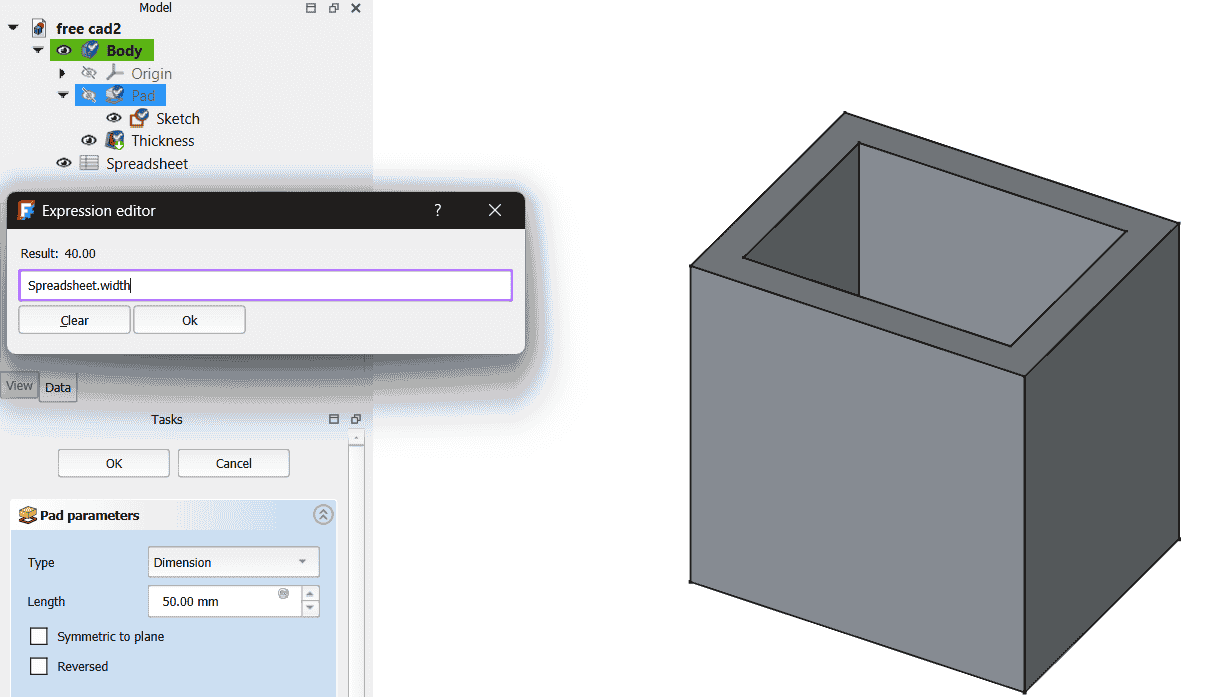
Save the spreadsheet, double click on sketch> padding> thickness.
On double clicking click on the blue icon and add code: spreadsheet.breadth to change the breadth
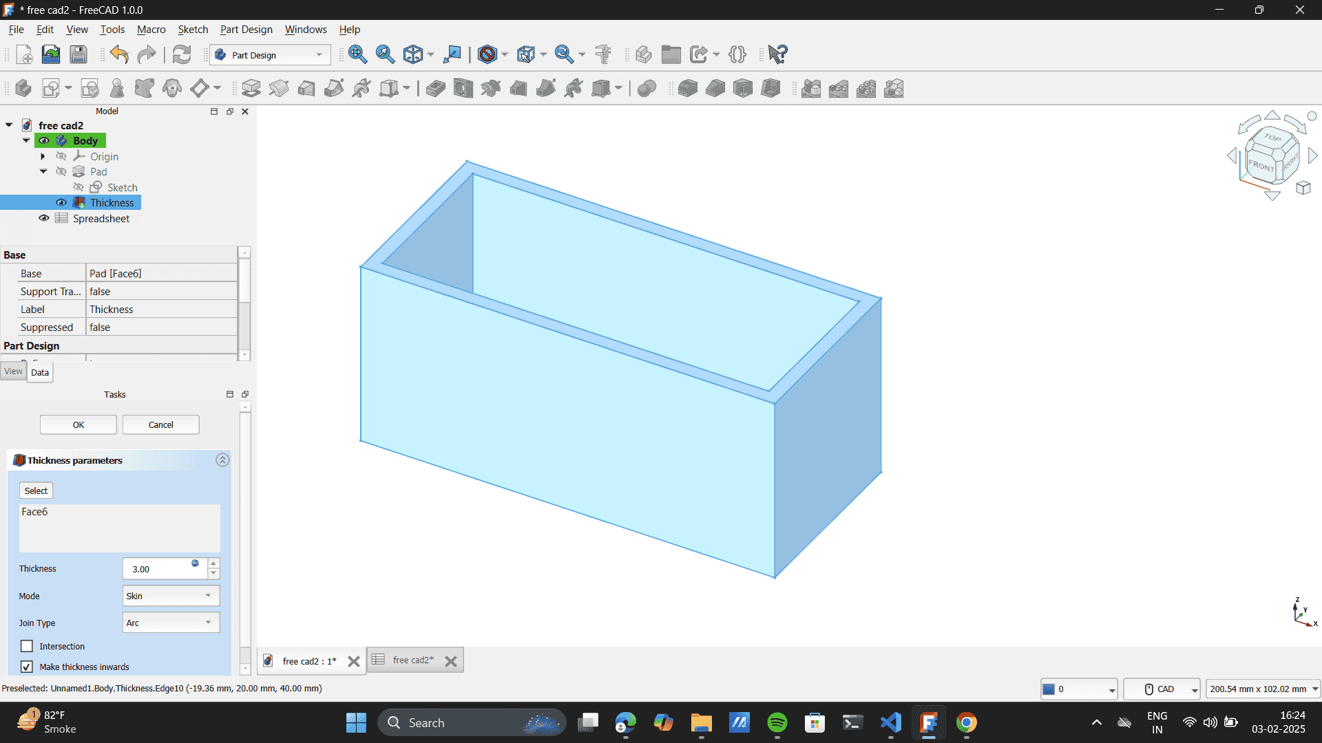
 8. Final Outcomes on change in dimensions-
Change one value, and the model updates instantly for length, breadth, width and thickness
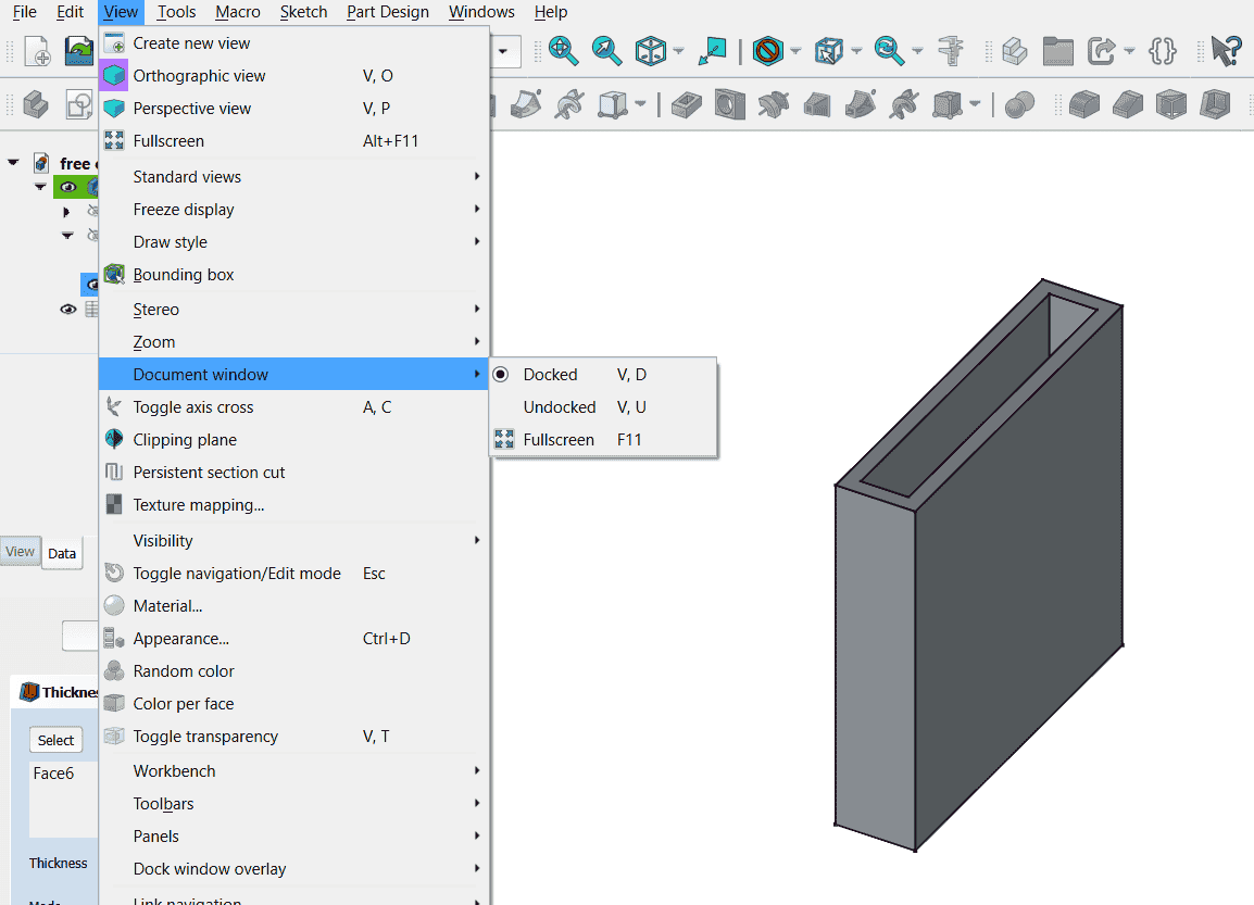
 9. Change materials and document view setting.
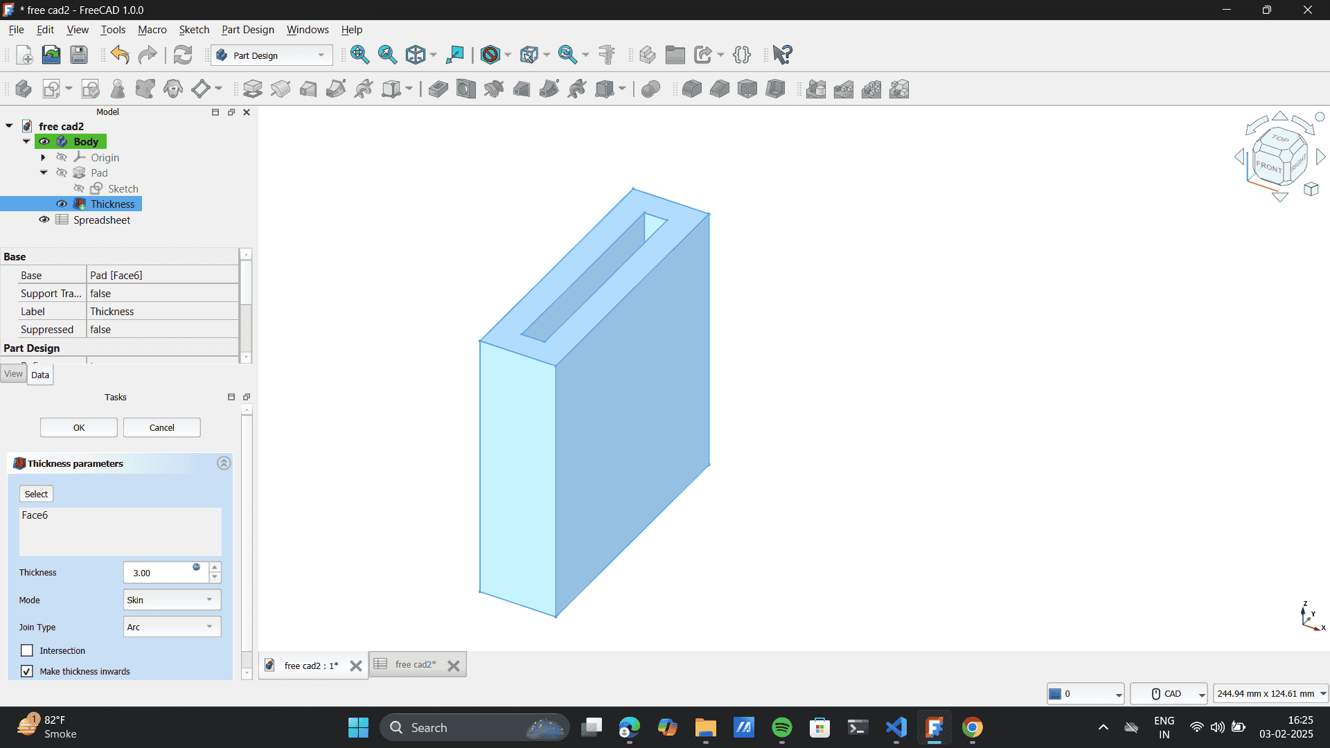
Tried Changing the material of the body.
Document viewing options.
Fusion 360:
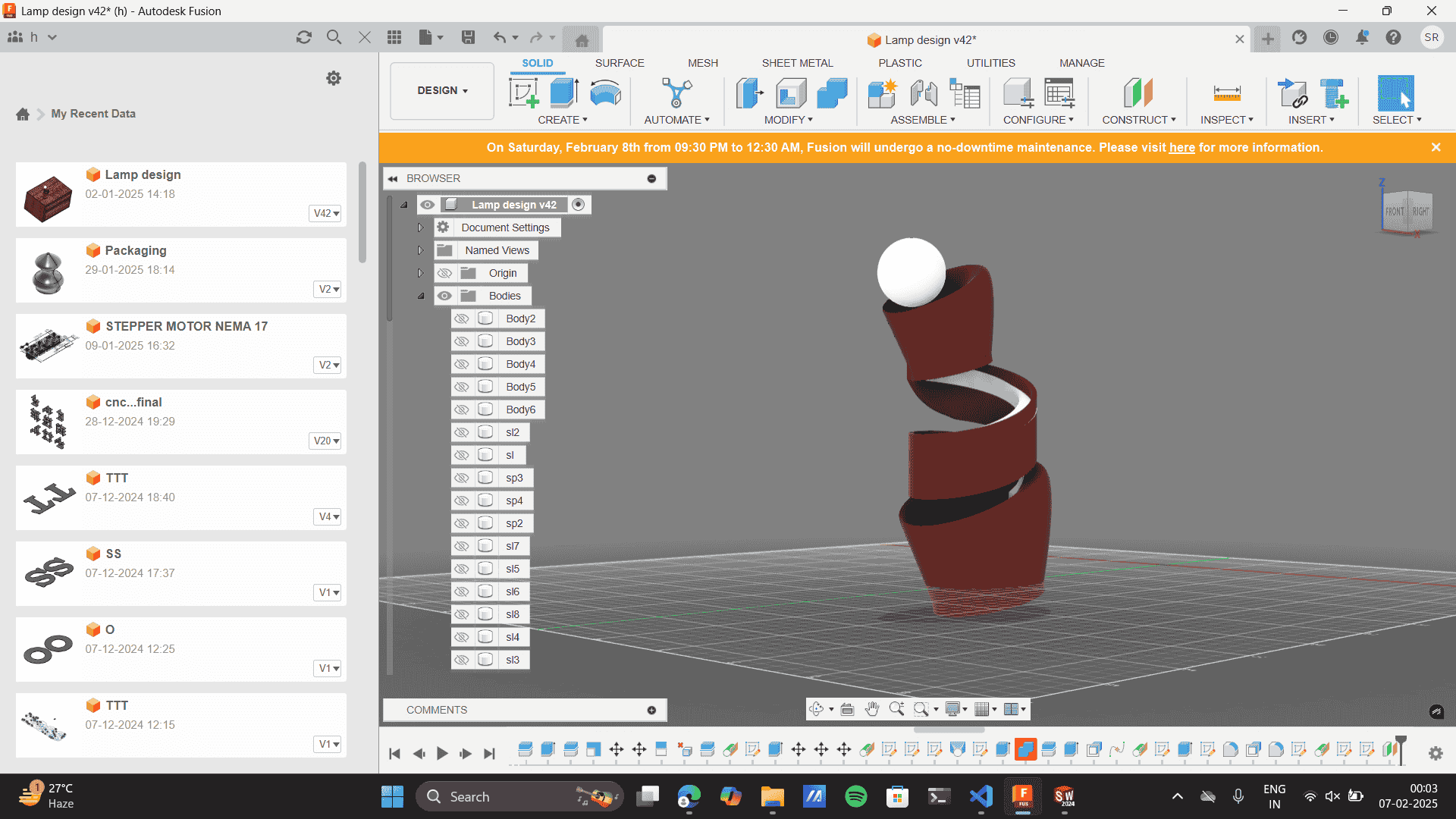
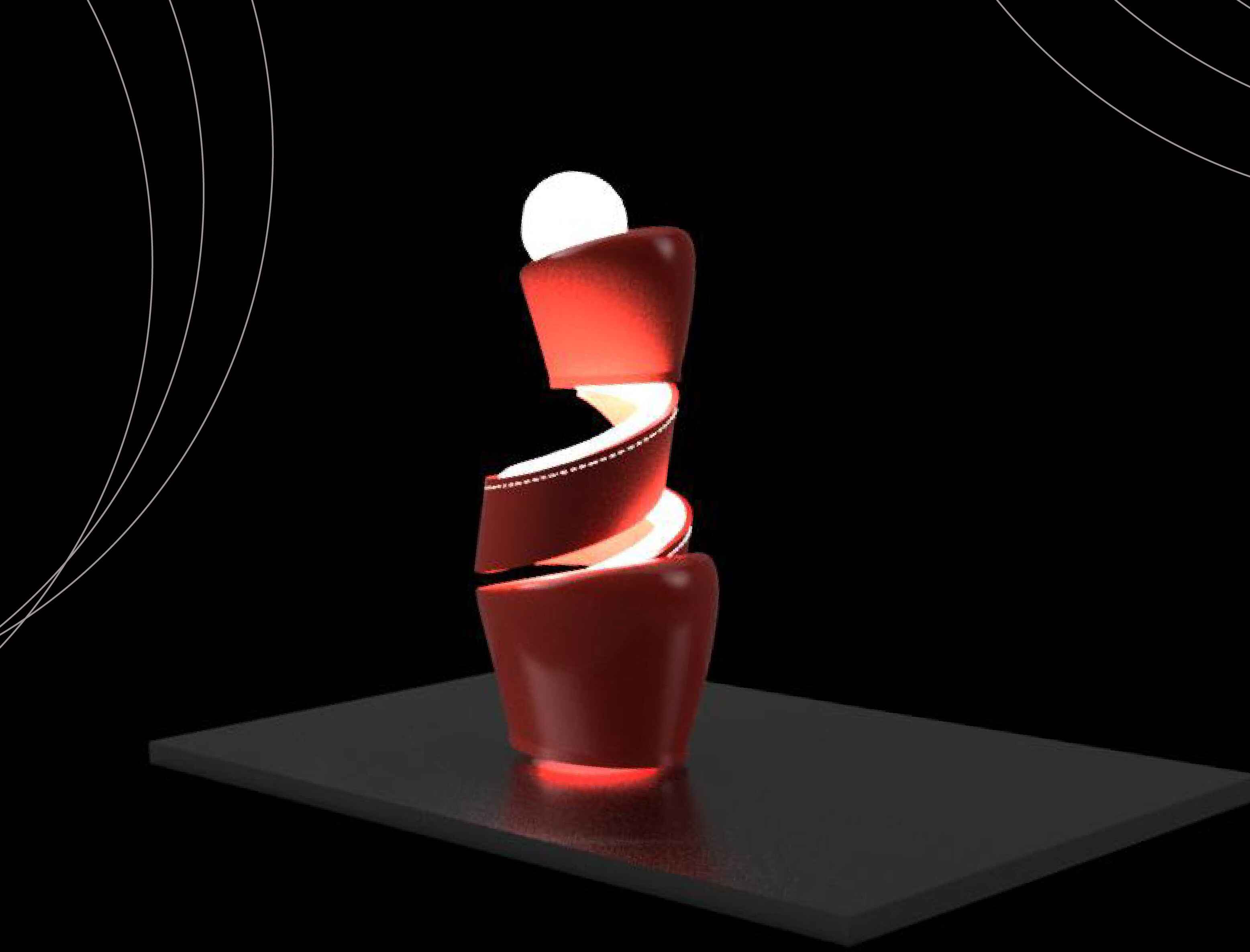
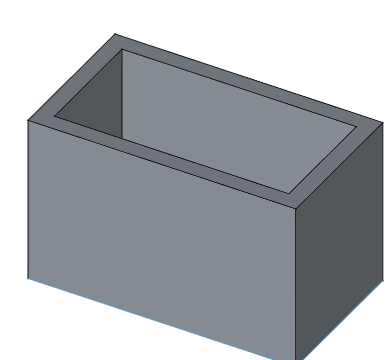
It integrates design, engineering, and manufacturing into one platform, enabling collaborative product development and prototyping. I have recently worked on a lamp design project using Fusion 360. Here, Imade multiple CAD designs, which would effeciently add to my 3d print quality.
I designed this lamp in Fusion 360 by first creating two cup-like structures using the Revolve tool. Then, you added a helix between them using the Sweep tool along a helical path. Combining these parts was challenging due to alignment and smooth transitions, which you resolved using the Combine (Join) tool and Fillet for a seamless connection. Finally, you optimized the model for 3D printing by ensuring proper wall thickness and exporting it as a stl file.
-
-
Installing Freecad: It will ask basic information like setting up the browser destination. I clicked 'Next' to
almost all of the set-up questions that the FreeCAD setup asked for the installation process.
- Shape Builder Is my Favourite tool on illustrator so I explored It here,