Assignment Brief:
- Design, build, and connect wired or wireless nodes with network or bus addresses, incorporating
local input and/or output devices.
- As a Gorup send a message between two different projects.
Networking and Communications
Networking and communication (in short) refers to how devices like computers, phones, or machines connect
and exchange data with each other using wired or wireless connections. It includes systems like the
internet, Wi-Fi, Bluetooth, and more, allowing information sharing, collaboration, and remote access.
In the week, I learn't a lot of theory knowledge. I started with referring to
week 04: Embedded Programming. Brushing up learns from there of Serial communication
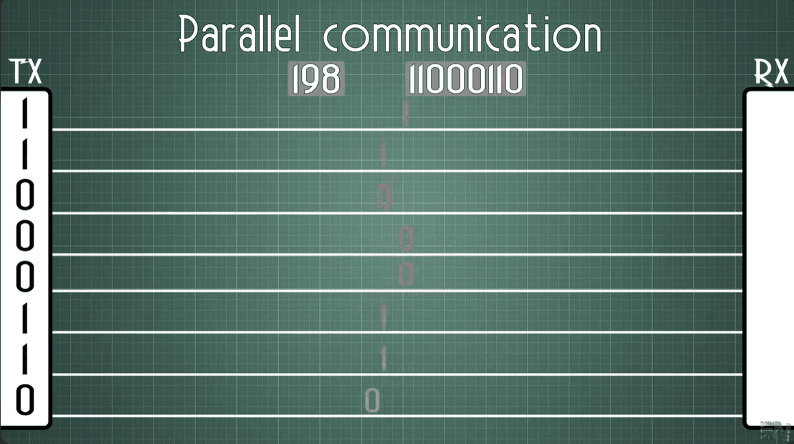
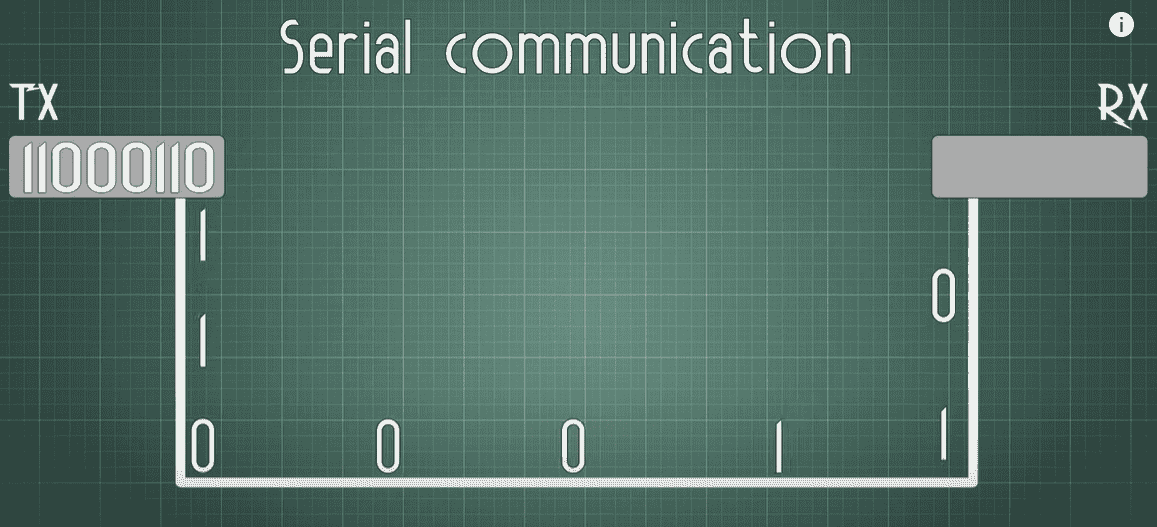
and parallel communication. Serial = like sending messages one by one over WhatsApp.
Parallel = like talking to someone in person using many words at once.
Parallel communication
serial communication
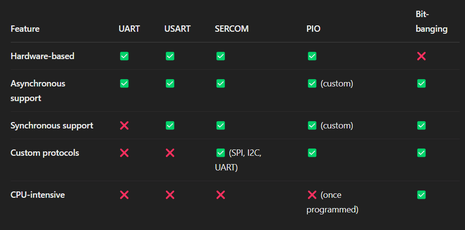
UART, USART, SERCOM, PIO, and Bit-bang
Then further I learn about UART, USART, SERCOM, PIO, and Bit-bang. are all types of serial communication
used by microcontrollers to exchange data with other devices like sensors, chips, or computers. They
send data one bit at a time over a line. Some use dedicated hardware (like UART and USART), others offer
flexible configuration (like SERCOM), custom protocol creation (like PIO), or rely entirely on software
control (like Bit-banging). Note: synchronization refer to clock. I would suggest to refer to
week 04: Embedded Programming week before diving into Networking and communication.
UART (Universal Asynchronous Receiver/Transmitter)
A hardware module for serial communication using 2 wires (TX & RX). It doesn't use a clock signal—relies
on timing.
USART (Universal Synchronous/Asynchronous Receiver/Transmitter)
Like UART but more advanced. Can do both asynchronous (UART) and synchronous (uses a clock)
communication.
SERCOM (Serial Communication Interface)
Found in Atmel, eg. Atitiny and Aurdino.
A flexible peripheral in some microcontrollers (like from Microchip) that can be configured as UART,
SPI, or I2C—based on your needs.
PIO (Programmable I/O)
Found in RP2040 (Raspberry Pi Pico). Lets you create custom I/O protocols in hardware, very flexible and
fast for custom tasks.
Bit-bang
A software-only method to simulate communication (like UART, SPI, etc.) using GPIO pins. Slower and
processor-heavy but works without special hardware.
RS-232, RS-422, and RS-485
RS-232, RS-422, and RS-485 are serial communication standards that define the electrical signals, wiring,
and data transmission rules for sending data between devices.
RS-232 is for short-distance, point-to-point communication (like old COM ports).
RS-422 supports longer distances and faster speeds with one sender and multiple receivers. That is
10 multipliers.
RS-485 is great for industrial use, allowing multiple devices to communicate over long distances
using a shared bus.
.png)
Some important terms I learn were:
🔁 Full-duplex: Data can be sent and received at the same time (like a phone call).
🔁 Half-duplex: Data can be sent or received, but not both at once (like a walkie-talkie).
Broad Hops is the number of devices (routers) a data packet passes through to reach its
destination.
Fewer hops = faster communication. Example: If data goes from PC → Router 1 → Router 2 → Server,
that’s a hop count of 3.
Broad Hops
Refers to how far a broadcast message can travel in a network.
Usually limited to avoid network congestion. A broadcast sends data to all devices on a local
network, and usually, routers block broadcasts from going too far to reduce traffic.
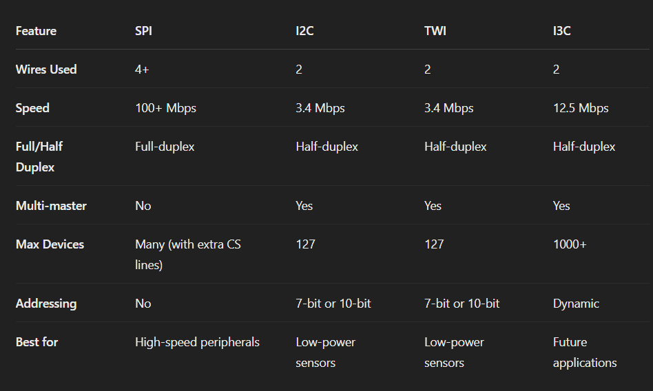
SPI, I2C AND I3C Communication
SPI (Serial Peripheral Interface), I2C (Inter-Integrated Circuit), and I3C (Improved Inter-Integrated
Circuit) are serial communication protocols used in electronics to allow microcontrollers to communicate
with other devices like sensors, displays, memory chips, and more.
They define how data is transferred between a central controller (called the master or the main) and
connected
devices (called slaves, secondary or peripherals), using specific rules, wire setups, and speeds
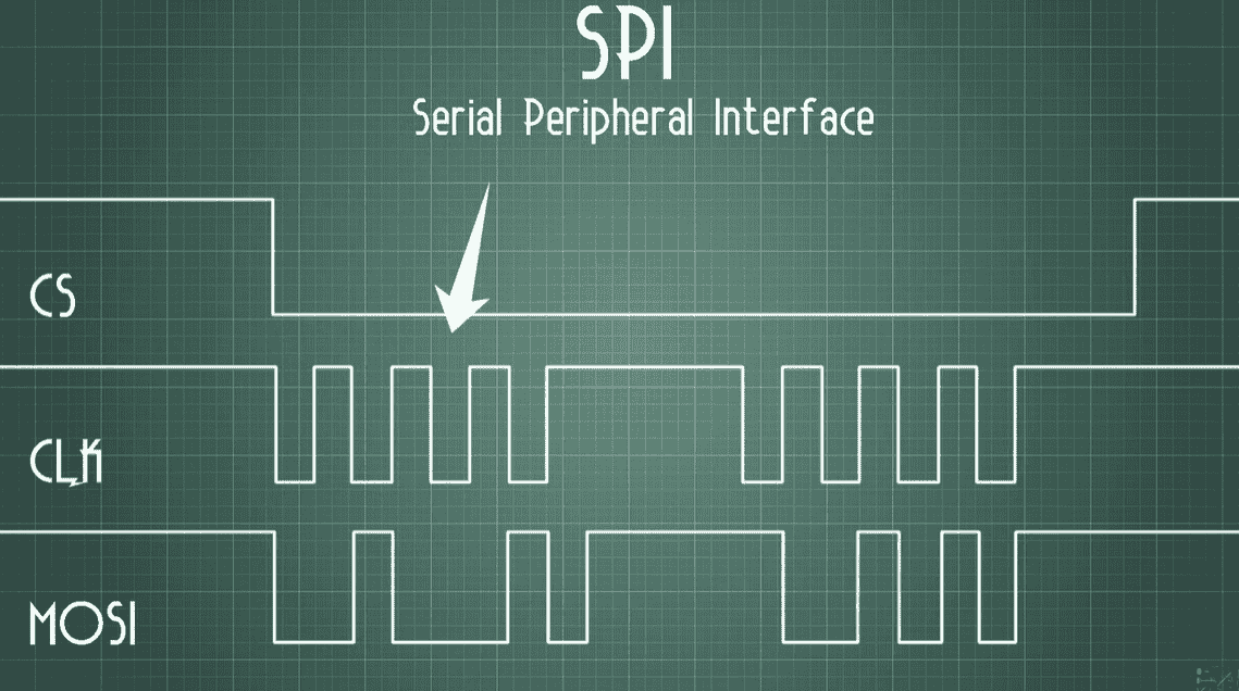
SPI (Serial Peripheral Interface)
- Fast, full-duplex, 4-wire protocol: MISO (main inslave out), MOSI (main out slave in), SCLK
(Clock), SS (Chip selector)
- main-secondary setup
- Good for short-distance, high-speed communication
- Devices need separate chip select lines
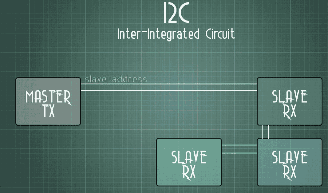
I2C (Inter-Integrated Circuit)
- 2-wire protocol SDA (Serial Data Line), SCL (Serial Clock Line).
- Supports multiple mains and secondary
- Uses addressing to manage devices (no extra chip select lines)
- Slower than SPI but simpler wiring
SPI (Serial Peripheral Interface)
I2C (Inter-Integrated Circuit)
I3C (Improved Inter-Integrated Circuit)
- Next-gen version of I2C
- Backward compatible with I2C
- Faster, lower power, dynamic addressing, better device management
- Ideal for modern sensors in smartphones, wearables, etc.
TWI (Two-Wire Interface)
TWI is essentially Atmel/Microchip’s name for I2C—it uses two wires (SDA & SCL) for communication
between devices. TWI = same as I2C, just a different name used by some microcontrollers. Functionally,
they work the same way.
 Some important terms I learn were: These terms are used in SPI communication to show data
direction
between the controller (main) and peripheral (secondary).
Some important terms I learn were: These terms are used in SPI communication to show data
direction
between the controller (main) and peripheral (secondary).
- PICO – Peripheral In, Controller Out
Data sent from controller to peripheral (like sending commands). Just as MISO in SPI Communication.
- POCI – Peripheral Out, Controller In
Data sent from peripheral to controller (like reading sensor data). Just as MISO in SPI
Communication.
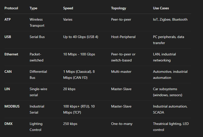
ATP, USB, Ethernet, CAN, LIN, Modbus, and DMX
These are all communication protocols—which means they are sets of rules that devices follow to send and
receive data. All of these are special languages that devices use to exchange data, each designed for a
specific purpose—computers, vehicles, factories, or lighting setups.
1. ATP (Advanced Transport Protocol)
- Used in wireless systems like Zigbee, Bluetooth, LoRa.
- Standard for connecting devices to computers.
Supports data + power; speeds up to 40 Gbps.
- Provides reliable data transfer with error checking and retransmission mechanisms.
- Needs a host device.
- Used in: Wireless sensor networks and industrial IoT applications.
2. USB (Universal Serial Bus)
- Serial communication standard for connecting peripherals to computers.
- Uses a host-controller model (host = PC, peripherals = devices).
- Supports different speeds: USB 1.1: 12 Mbps to USB 4.0: 40 Gbps
- Use Cases:
Connecting peripherals (mice, keyboards, printers, etc.).
Data transfer (external drives, flash drives).
Charging and powering devices.
3. Ethernet
- Wired networking standard used for local area networks (LANs).
- Uses packet-based communication with MAC addressing.
\- Speed variations:
Fast Ethernet: 100 Mbps to 40G/100G Ethernet: High-performance networking.
- Use Cases:
Office and industrial networking.
IoT and embedded systems (with Ethernet-enabled microcontrollers).
Server-to-server high-speed communication.
4. CAN (Controller Area Network)
- Multi-main, differential serial bus used in automotive and industrial applications.
- Supports real-time communication with priority-based arbitration.
- CAN FD (Flexible Data Rate): Up to 8 Mbps.
- Uses differential signaling for noise immunity.
Works over a twisted pair for robustness in noisy environments.
- Use Cases:
Automotive (ECU communication: engine, ABS, airbags).
Industrial automation (robots, factory control).
5. LIN (Local Interconnect Network)
- Simplified, low-cost alternative to CAN for non-critical applications.
- Uses single-wire communication with a main-secondary topology.
- Lower speed than CAN (~19.2 kbps to 20 kbps).
- Use Cases:
Car window controls, seat adjustment, lighting.
Low-cost sensor communication in vehicles.
6. Modbus
is a communication protocol used in industrial automation.
Devices like PLCs, sensors, and controllers use it to exchange data. Use: Factories, SCADA systems,
process control.
7. DMX (Digital Multiplex) is a protocol for controlling stage lighting and effects.
Sends fast, continuous signals to lights, fog machines, and dimmers.
Use: Theatres, concerts, event lighting setups.
OSI Layers
The OSI (Open Systems Interconnection) Model is a conceptual framework that describes how data moves
or travels from one device to another over a network, in 7 layers, each with a specific function.
Real-World Example of OSI Model in Action (Web Browsing)
You type "www.google.com" in your browser (Layer 7 - HTTP).
The browser encrypts the request using TLS (Layer 6 - SSL/TLS).
A session is established with Google’s server (Layer 5 - TCP Session).
The data is broken into packets using TCP (Layer 4 - Transport).
Each packet is assigned an IP address (Layer 3 - IP Routing).
The packet is sent over an Ethernet/Wi-Fi connection (Layer 2 - MAC, Wi-Fi).
The data is converted into electrical signals or radio waves (Layer 1 - PHY).
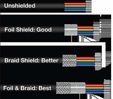
Wire sheilding
Cable shielding protects signal wires from electrical noise and interference. It's used in communication,
audio, and data cables to ensure clean signal transmission.
Different types (Unshielded, Foil, Braid, Foil + Braid) offer varying levels of protection—more
shielding means better performance, especially in noisy environments. More shielding = better signal
quality and less interference.
Unshielded – No protection from interference.
Foil Shield – Basic protection using a thin foil wrap.
Braid Shield – Better shielding with a metal mesh.
Foil & Braid – Best protection using both foil and mesh.
Assignment: Networking and Communication
My this week's assignment is divided into to three parts
- Aurdino to Arduino using I2C
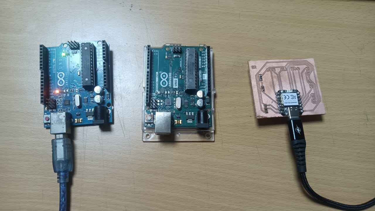
- Xiao RP2040 to Arduino UNO using I2C
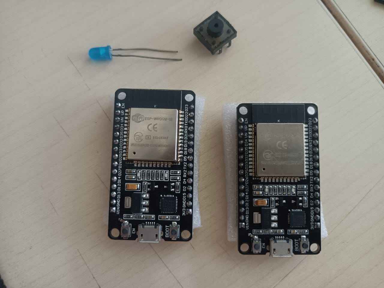
- NodeMCU (ESP8266) to NodeMCU using wireless connection
Aurdino to Arduino to XAIO using I2C
NodeMCU (ESP8266) to NodeMCU using wireless connection
I2C Between Arduinos
I referred to the Instructables link, I2C Between Arduinos by Cornelam. I2C (Inter-Integrated Circuit) is a serial communication
protocol that lets multiple devices (like sensors or other Arduinos) talk using just two wires:
SDA – Serial Data Line
SCL – Serial Clock Line
One Arduino acts as the main, and others as secondary. Each secondary has a unique address, and the main
controls all communication.
Efficient for connecting many devices.
Less wiring.
Used for sensor modules, EEPROMs, other Arduinos, etc.
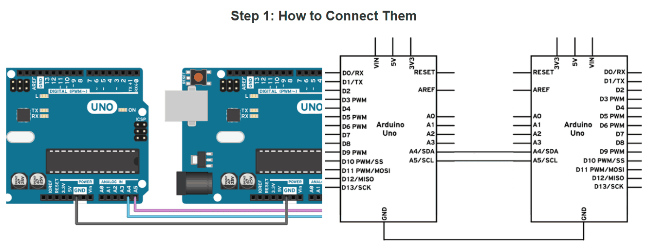
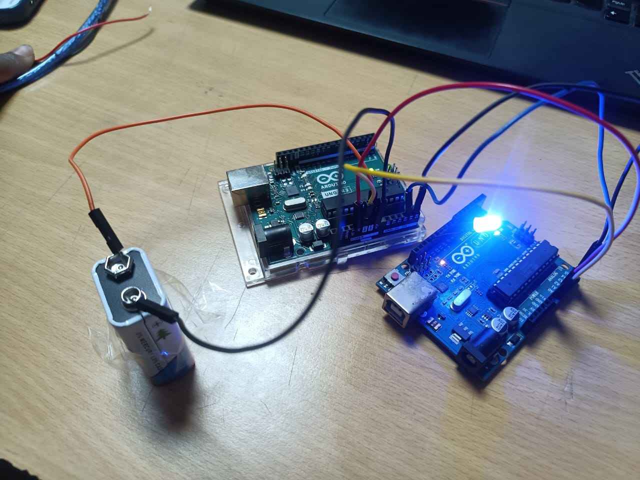
Wire connections
Connect pins A4/SDA and A5/SCL on one Arduino to the same pins on the other one.
The GND line has to be common for both Arduinos. Connect it with a jumper.
Further, I connected an LED at pin 12 and GND to secondary Aurdino.
Note: Remember never to connect 5 V and 3.3 V Arduinos together. It won't
hurt the 5V Arduino, but it will certainly annoy its 3.3 V!
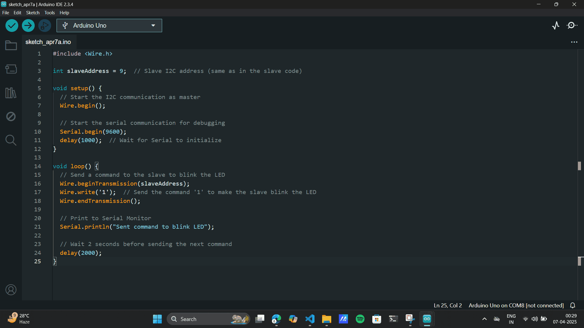
Uploaded the main code to the Arduino main.
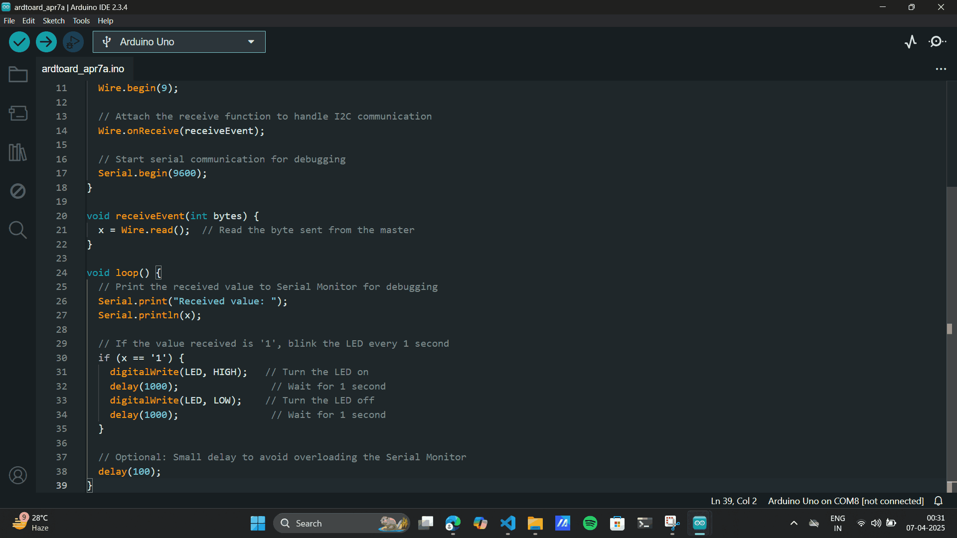
Uploaded the secondary code to the Arduino secondary.
            #include

            int slaveAddress = 9;  // Slave I2C address (same as in the slave code)

            void setup() {
              // Start the I2C communication as main
              Wire.begin();

              // Start the serial communication for debugging
              Serial.begin(9600);
              delay(1000);  // Wait for Serial to initialize
            }

            void loop() {
              // Send a command to the slave to blink the LED
              Wire.beginTransmission(slaveAddress);
              Wire.write('1');  // Send the command '1' to make the slave blink the LED
              Wire.endTransmission();

              // Print to Serial Monitor
              Serial.println("Sent command to blink LED");

              // Wait 2 seconds before sending the next command
              delay(2000);
            }
        #include

        int LED = 12;  // Pin for the LED
        int x = 0;     // Variable to store received data

        void setup() {
          // Define the LED pin as Output
          pinMode(LED, OUTPUT);

          // Start the I2C Bus as Slave with address 9
          Wire.begin(9);

          // Attach the receive function to handle I2C communication
          Wire.onReceive(receiveEvent);

          // Start serial communication for debugging
          Serial.begin(9600);
        }

        void receiveEvent(int bytes) {
          x = Wire.read();  // Read the byte sent from the main
        }

        void loop() {
          // Print the received value to Serial Monitor for debugging
          Serial.print("Received value: ");
          Serial.println(x);

          // If the value received is '1', blink the LED every 1 second
          if (x == '1') {
            digitalWrite(LED, HIGH);   // Turn the LED on
            delay(1000);                // Wait for 1 second
            digitalWrite(LED, LOW);    // Turn the LED off
            delay(1000);                // Wait for 1 second
          }

          // Optional: Small delay to avoid overloading the Serial Monitor
          delay(100);
          }
Here:
LED is the pin where the LED is connected and
x stores the received data from the Main.
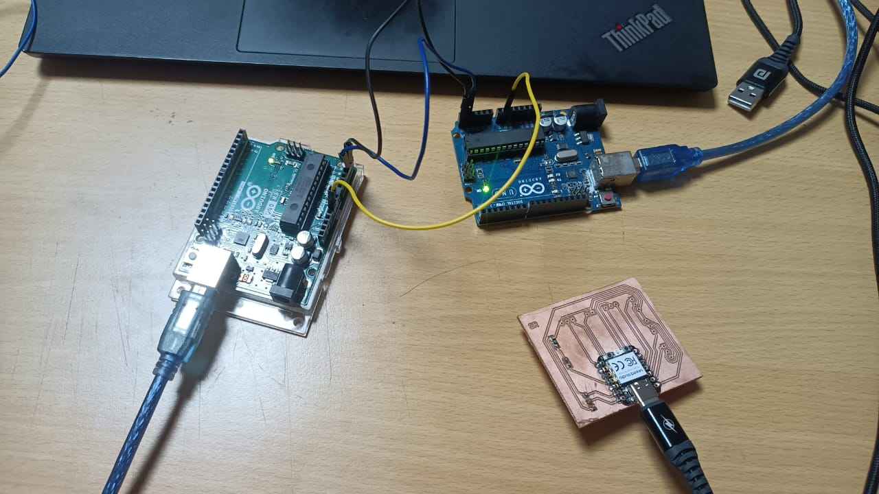
Once the code was uploaded to both the Arduino's and the program ran smoothly, the code was stored in the
memory for aurdino.
So I removed the USB cables for both and gave a Power battery supply to the Main Arduino. The Arduino
didnt work on a Lower Battery Supply. It needed a
Supply of 5V or above.
Note: Use the VIN pin for to power the Arduino, as VIN + GNd goes through
regulator and
powers it smoothly.
Xiao RP2040 to Arduino UNO using I2C
Referring to Documentation of my senior, Siddharth Agarwal for Xiao RP2040 to Arduino UNO using I2C. I learnt a few things from the
documentation
Like:
One, RP2040 to RP2040 does not work due to a bug in the chip itself, and Two, When connecting
RP2040
to anything else, to be cautious of the voltage difference.
He has added my professor
Jesal Sir's
Quote which I learnt the hard way buy burning a Xaio. Quoting
“One has to be careful here, since the XIAO operates at 3.3 V while the Uno operates at 5 V. The I2C
connection operates at whatever the main is operating at. So the XIAO being the Primary or main
would work for the Uno but not the other way
!"
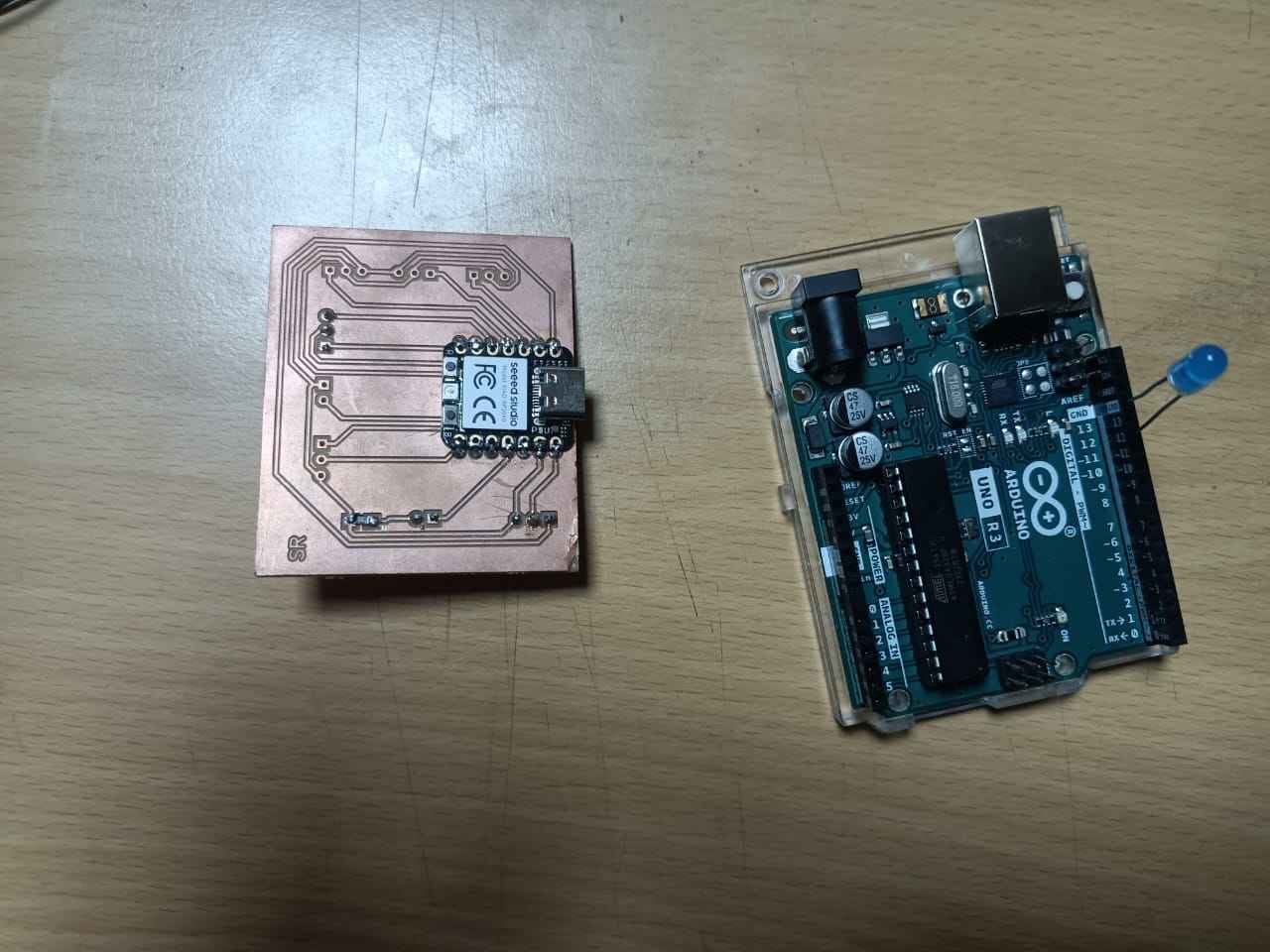
Wire connections
SDA (D4) [XIAO] to SDA (A4) [Uno]
SCL (D5) [XIAO] to SCL (A5) [Uno]
common GND
LED on Arduino and pin 12 and GND
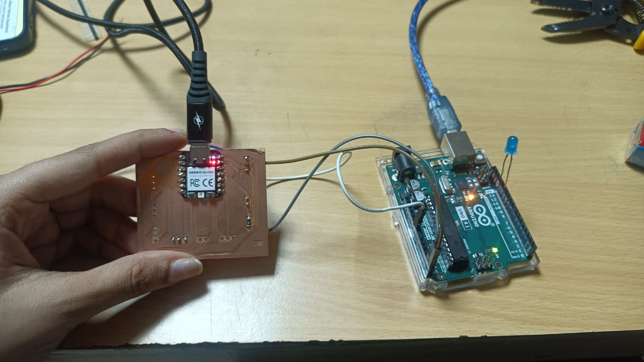
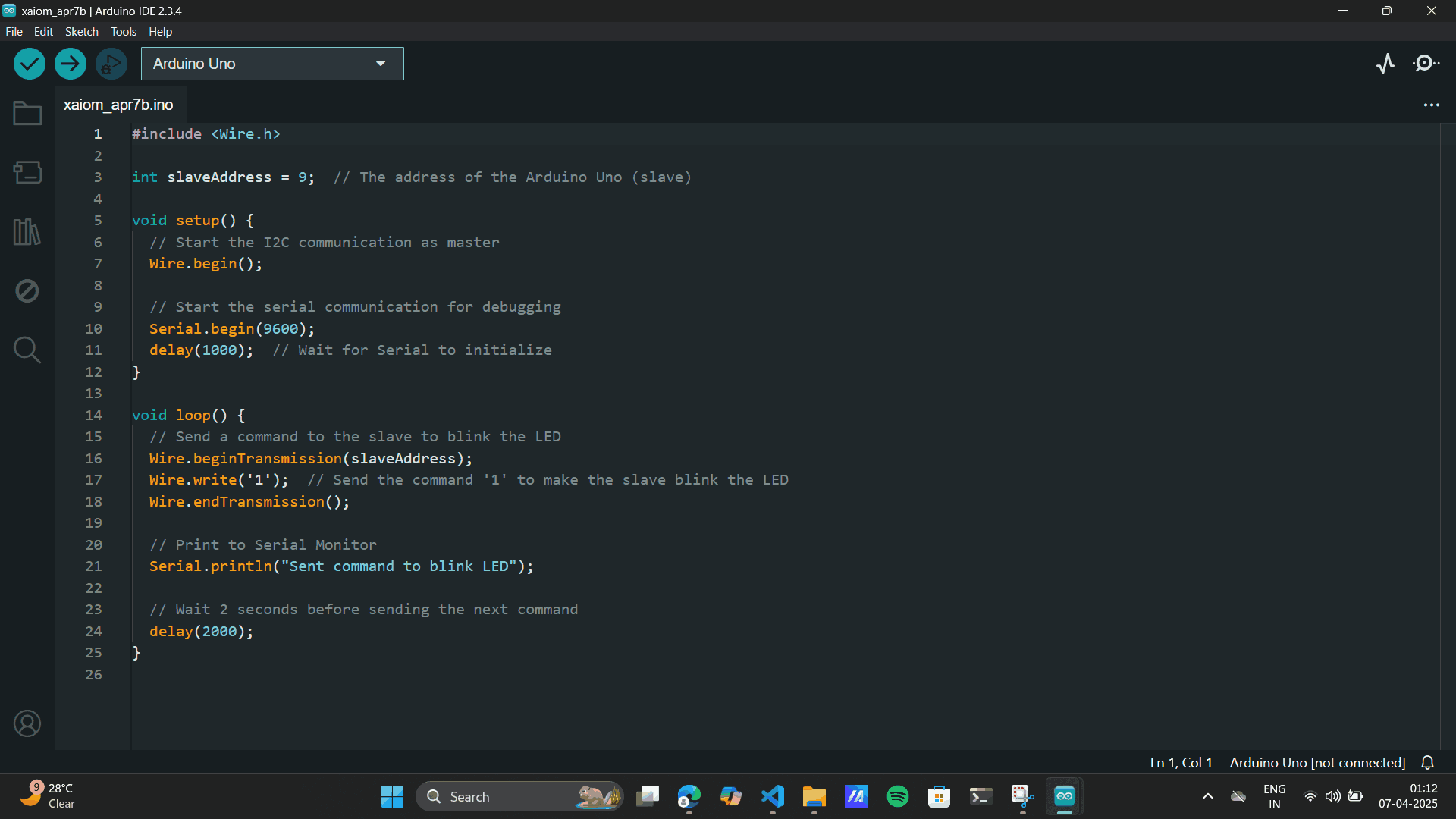
Uploaded the main code to the XAIO main.
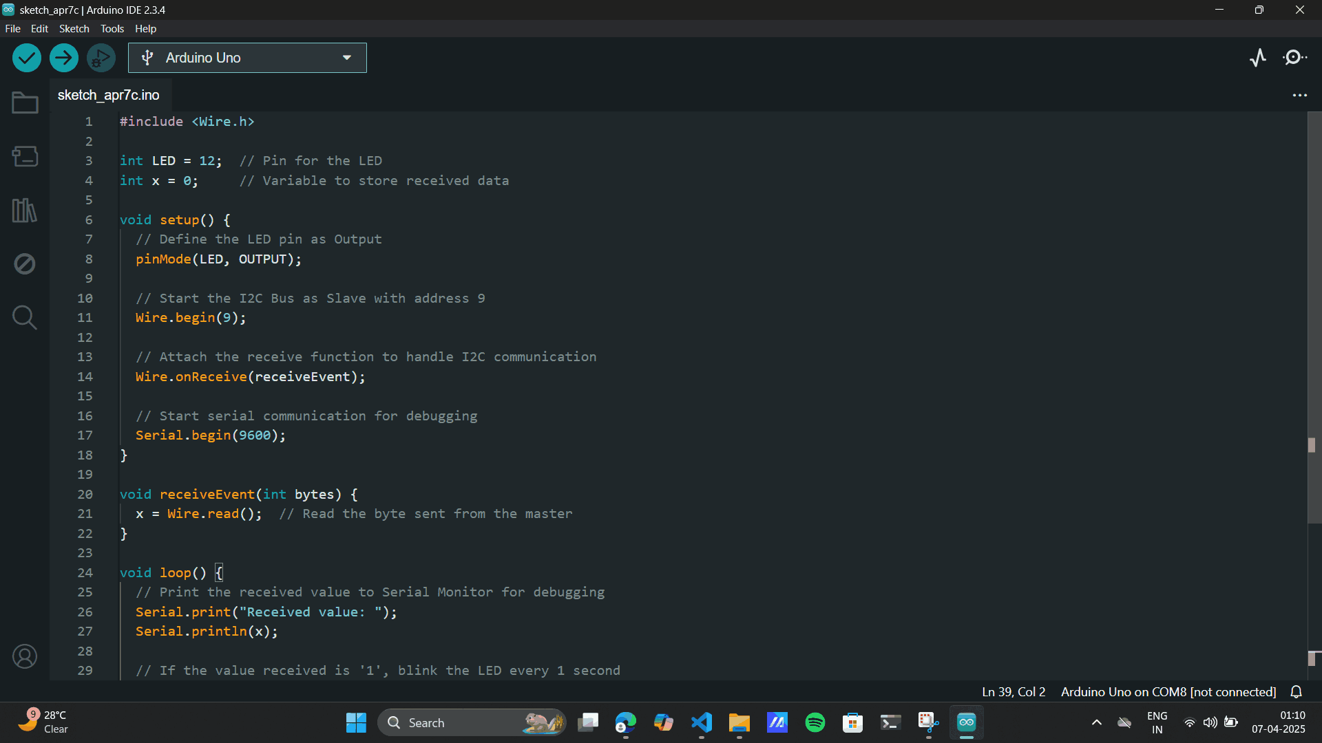
Uploaded the secondary code to the Arduino secondary.
    #include

        int slaveAddress = 9;  // The address of the Arduino Uno (slave)

        void setup() {
          // Start the I2C communication as master
          Wire.begin();

          // Start the serial communication for debugging
          Serial.begin(9600);
          delay(1000);  // Wait for Serial to initialize
        }

        void loop() {
          // Send a command to the slave to blink the LED
          Wire.beginTransmission(slaveAddress);
          Wire.write('1');  // Send the command '1' to make the slave blink the LED
          Wire.endTransmission();

          // Print to Serial Monitor
          Serial.println("Sent command to blink LED");

          // Wait 2 seconds before sending the next command
          delay(2000);
        }
Secondary Code for Arduino
#include

    int LED = 12;  // Pin for the LED
    int x = 0;     // Variable to store received data

    void setup() {
      // Define the LED pin as Output
      pinMode(LED, OUTPUT);

      // Start the I2C Bus as Slave with address 9
      Wire.begin(9);

      // Attach the receive function to handle I2C communication
      Wire.onReceive(receiveEvent);

      // Start serial communication for debugging
      Serial.begin(9600);
    }

    void receiveEvent(int bytes) {
      x = Wire.read();  // Read the byte sent from the main
    }

    void loop() {
      // Print the received value to Serial Monitor for debugging
      Serial.print("Received value: ");
      Serial.println(x);

      // If the value received is '1', blink the LED every 1 second
      if (x == '1') {
        digitalWrite(LED, HIGH);   // Turn the LED on
        delay(1000);                // Wait for 1 second
        digitalWrite(LED, LOW);    // Turn the LED off
        delay(1000);                // Wait for 1 second
      }

      // Optional: Small delay to avoid overloading the Serial Monitor
      delay(100);
    }
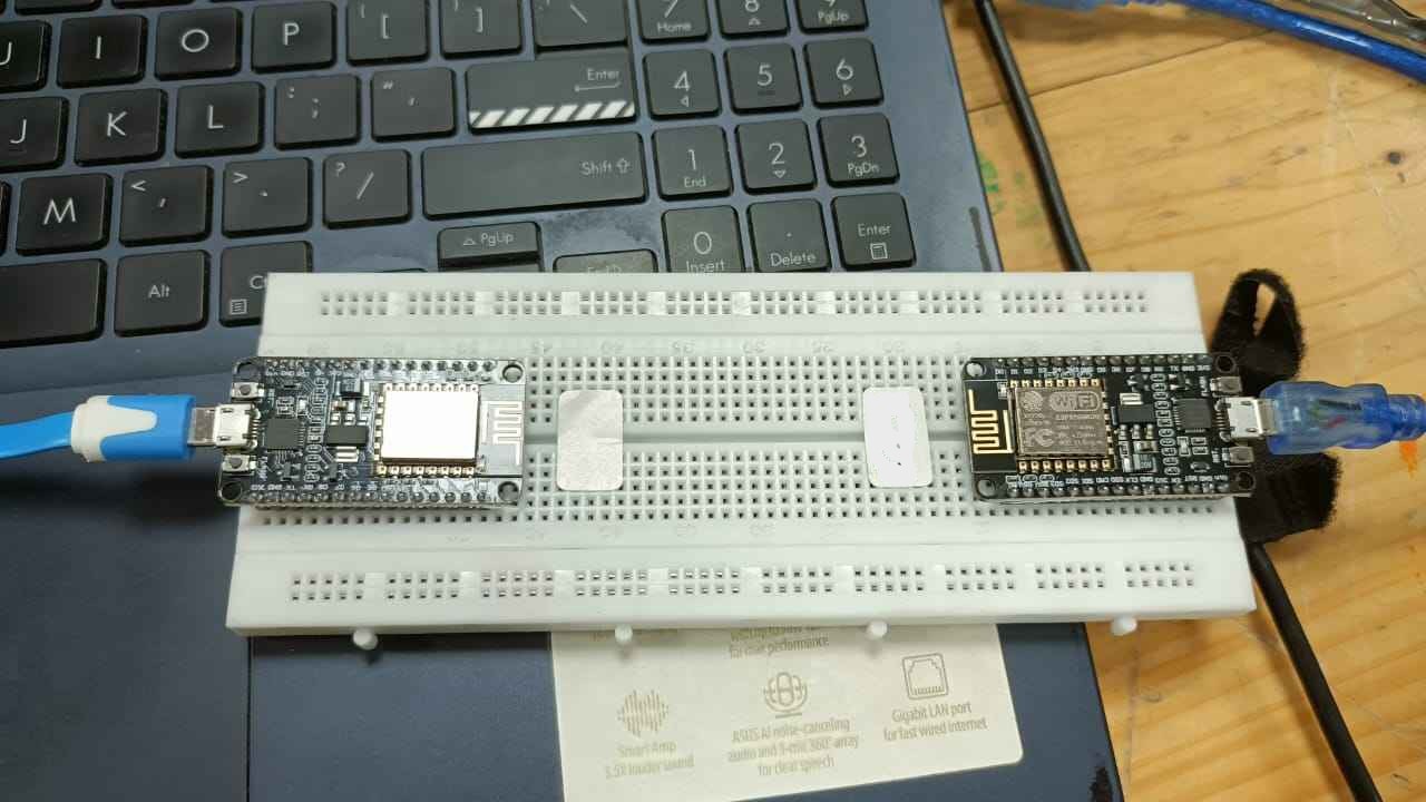
NodeMCU to NodeMCU
The NodeMCU uses an ESP8266 microcontroller which can communicate wirelessly over wi-fi or bluetooth. In this
week, we communicate between the nodeMCUs using a wireless communication protocol called ESPNow, which runs
on top of WiFi. Again I referred to
Siddharth's Documentation for Node MCU connection
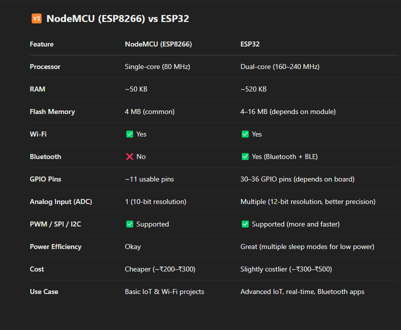
Difference between NODE MCU and ESP32
The NodeMCU and ESP32 are both popular microcontroller boards used in IoT and embedded projects, but they
differ in capabilities, hardware, and use cases.
Node MCU pinout:
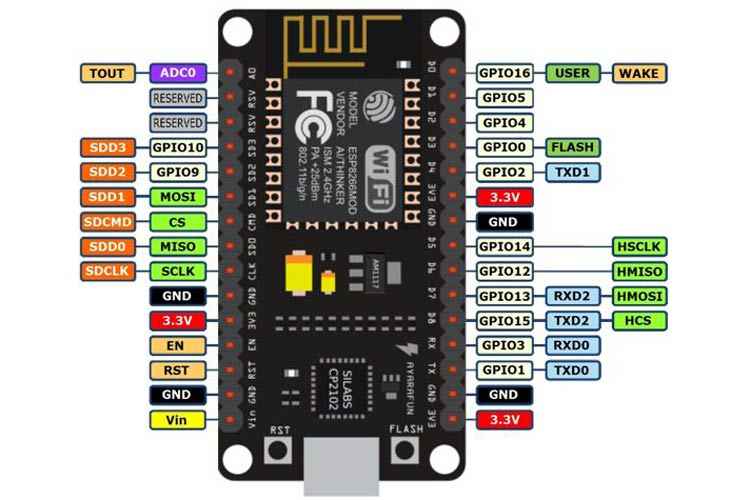 Setting up the IDE
In order to program the NodeMCU, we need to first install the necessary drivers. This can be found on this
link
Silicone
Labs for Arduino IDE. Most NodeMCU boards use a CP210x USB to UART bridge made by Silicon Labs.
Without the correct driver, your computer might not detect the board properly, and you won't be able to
upload code from the Arduino IDE or any other development environment.
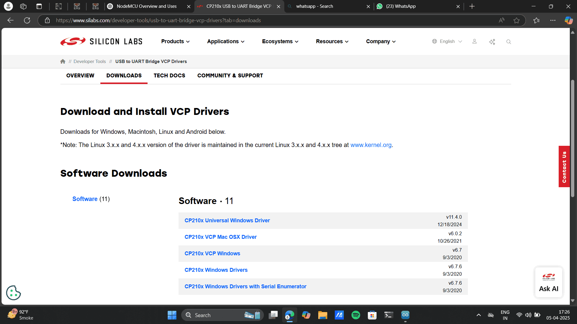
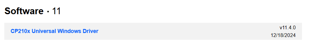
I installed the Universal windows driver and ran the program on my computer, and run the
programme on software.
 Board setup on Arduino IDE
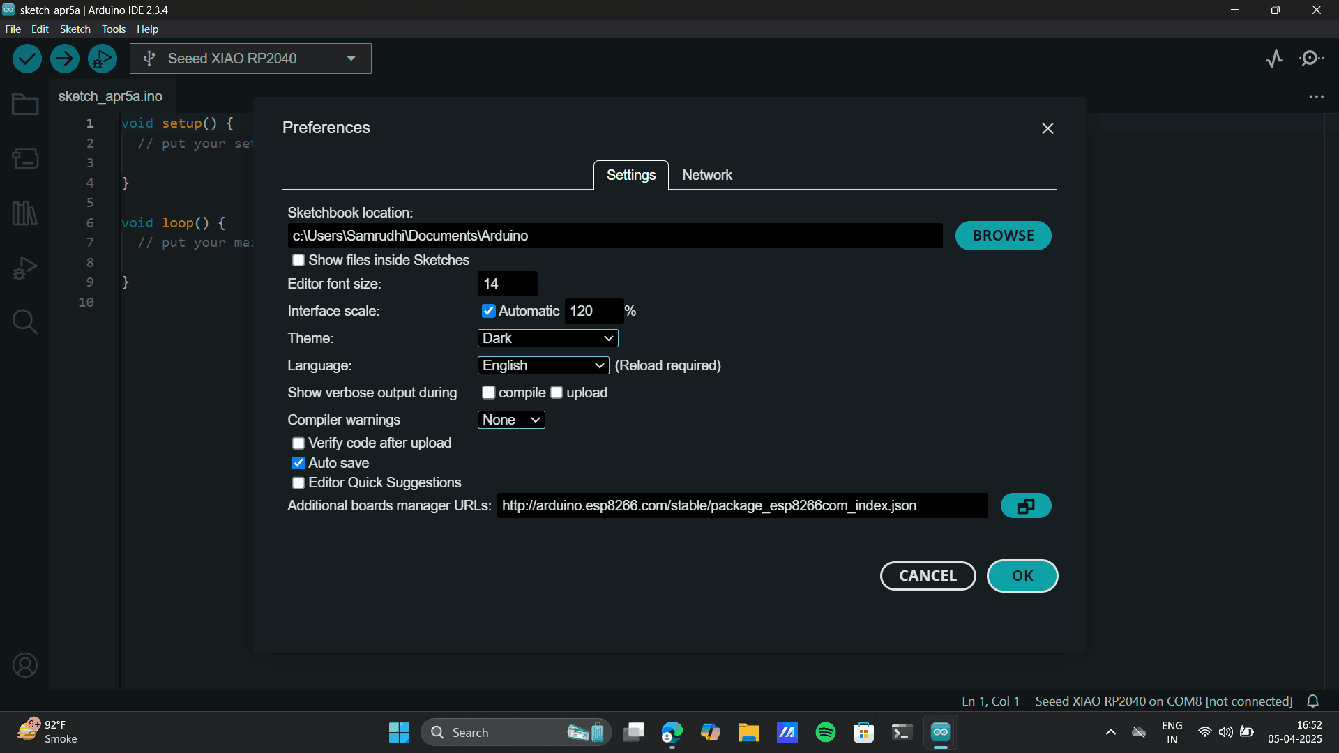
I opened up Arduino IDE and went to “Preferences” under File.
There, under “Additional Boards Manager URL” I added the following link:
https://arduino.esp8266.com/stable/package_esp8266com_index.json
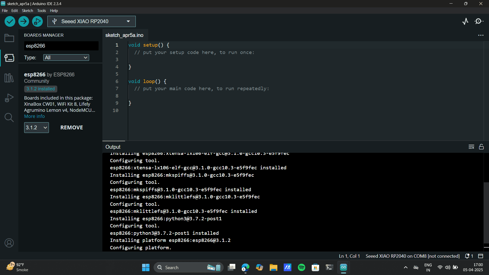
and finally, I went to the Board Manager under Tools and searched for ESP8266 by Community and installed it.
Tools> Boards> Board manager to set up the
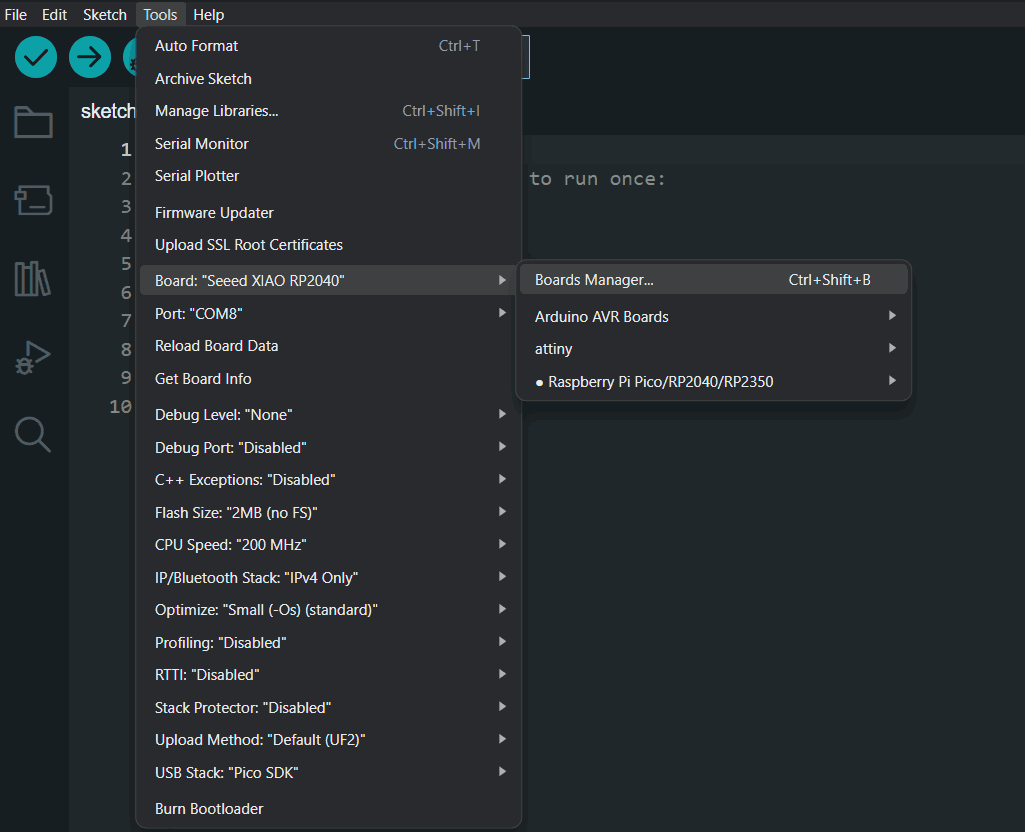
Add the board manager URL link.
Preferences> Library> Search for esp8266.
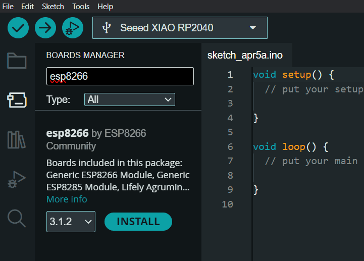
Install esp8266 by esp8266 community.
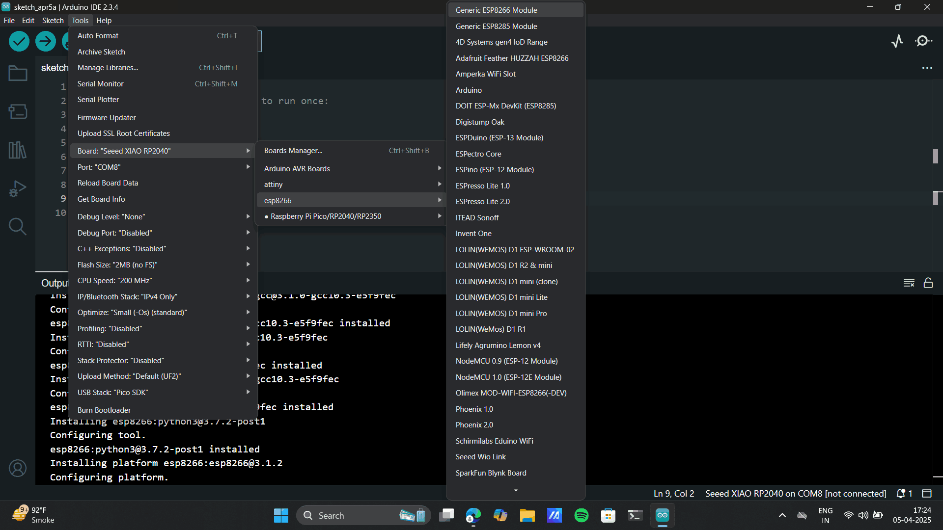
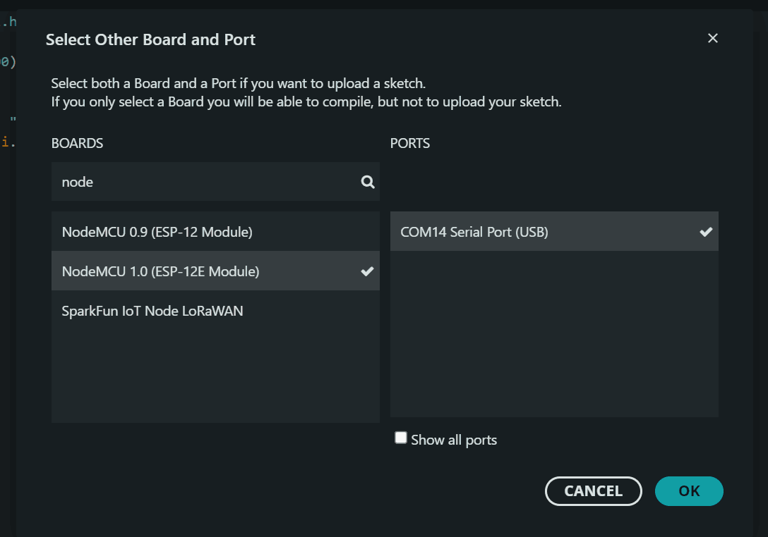
Tools> Boards> esp8266> Generic esp8266 Module.
Connect NodeMCU to the port and set the board as well.
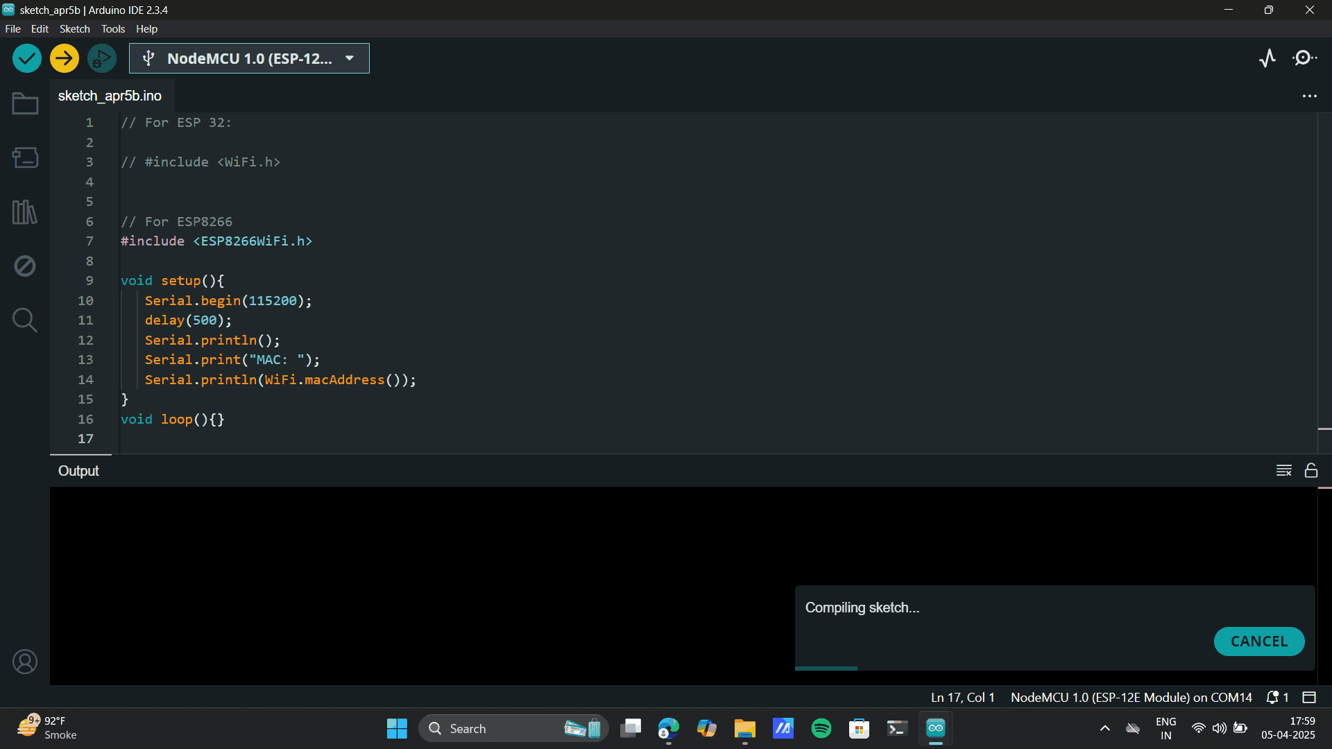
Generating Mac address
To start with any wireless communication, we need to first find the Mac Address of the microcontroller we are
using. Mac Address has nothing to do with the MacBook or Apple and actually stands for “Media Access Control
Address”. It is the unique address/identifier of a controller that can communicate wirelessly.
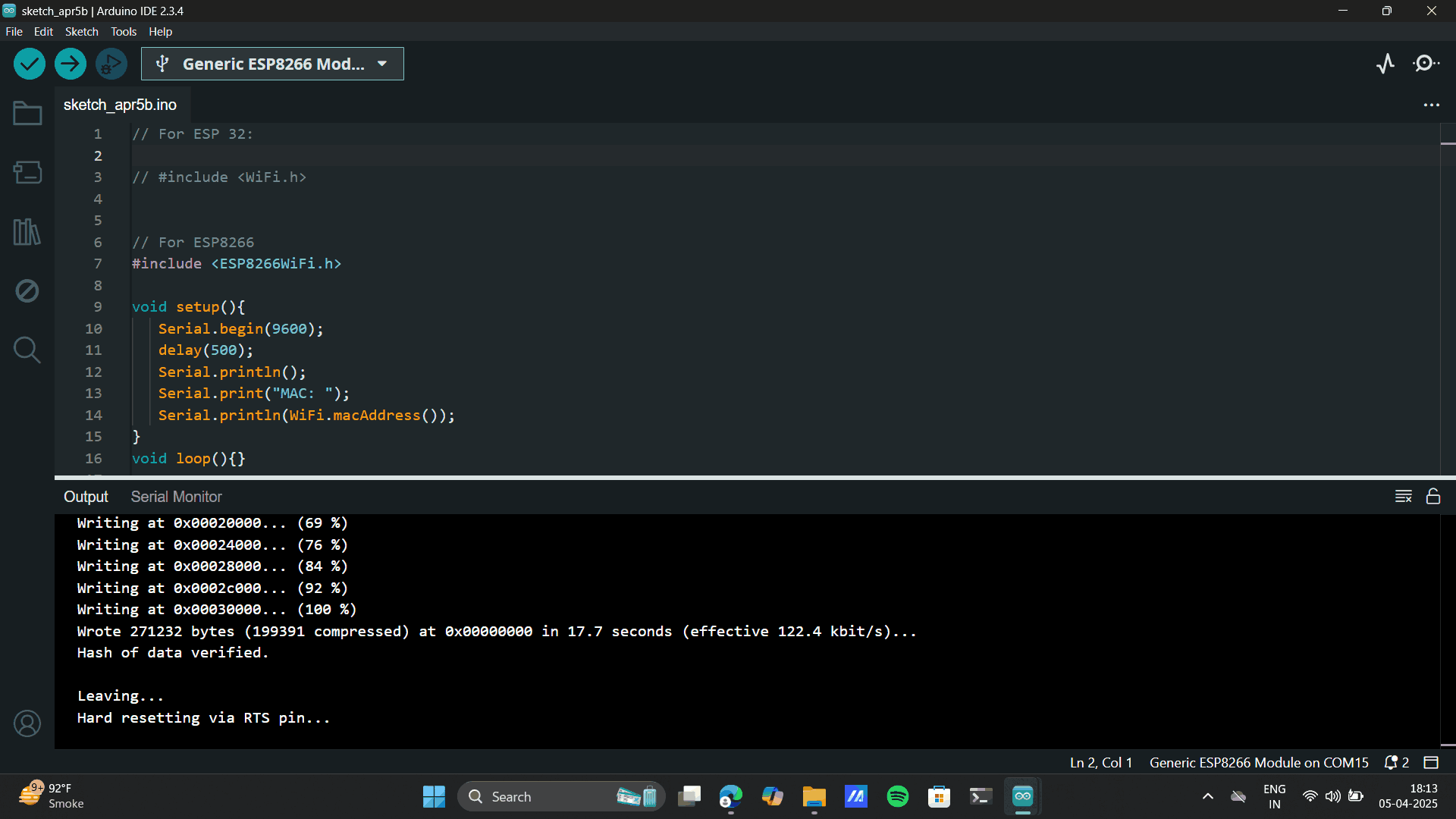
You simply run the Mac Address code after connecting your microcontroller and once uploaded, hit the “Reset”
button on your microcontroller and look at your Serial Monitor. You will find the unique 6-figure address of
your controller.
Add Mac Address code.
                // For ESP 32:

                // #include


                // For ESP8266
                #include

                void setup(){
                   Serial.begin(9600);
                   delay(500);
                   Serial.println();
                   Serial.print("MAC: ");
                   Serial.println(WiFi.macAddress());
                }
                void loop(){}
Upload the Mac Address code.
Press Control> Shift M> Serial Monitor
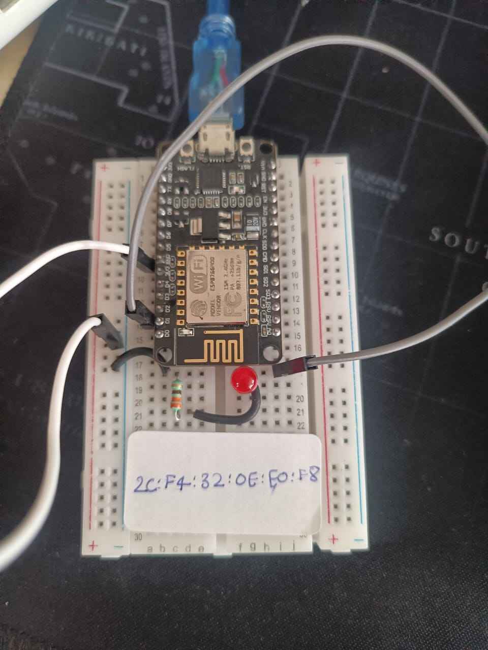
Secondary Mac Address code.
.png)
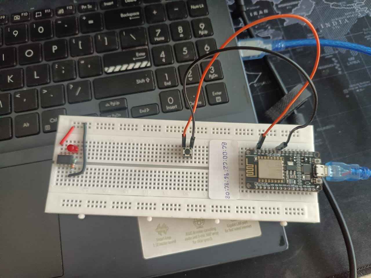
Main Mac Address Code
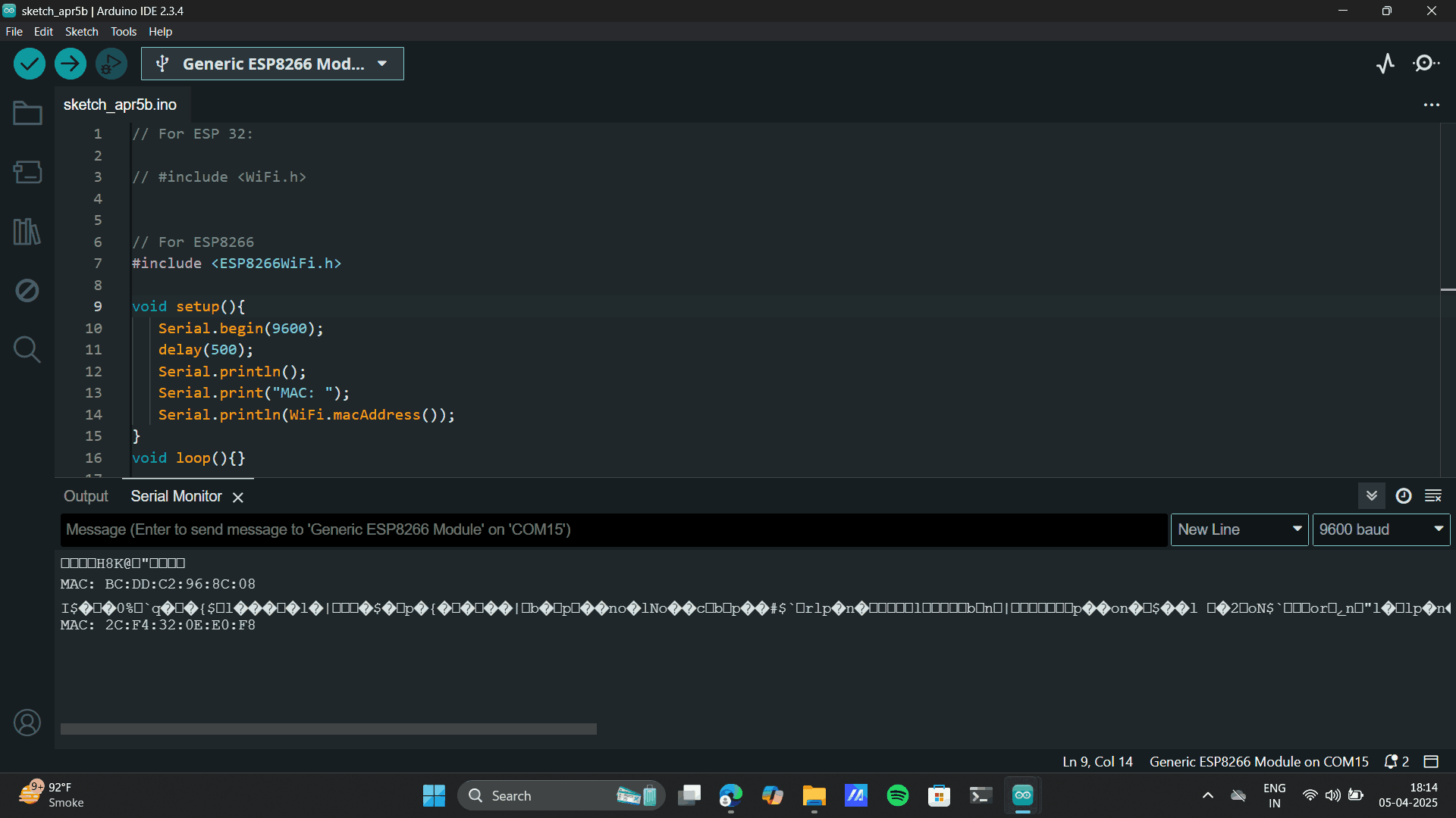
Secondary Mac Address
Main Mac Address
One Way Communication
Later, I shifted all the connection to the same board. I tried the whole process on my own, however it didnt
work out, could be the
code error which chatgpt provided me. Later, in my college lecture of IOT wireless communication was taught,
thanks to Chinmayi sir,
he made the process very easy which seemed very complex when I tried it alone.
The first thing that we explored once the Mac adress was set, was One Way Communication of Push button to
led blink. This was the Momentary switch. A momentary switch is a switch that stays on only while being
pressed. Once released, it returns to its off position. Common in buttons like doorbells or keyboard keys.
For the follwing I made the connections:
Main Node MCU: Connect Switch to GND AND D2.
Secondary Node MCU: Connect LED to GND AND D2.
Upload the below main push button code to main Node MCU.
In the Mac address put the Secondary's MAC Address.
                #include
                    #include

                    #define BUTTON_PIN D2  // GPIO13

                    uint8_t receiverMac[] = {0xF4, 0xCF, 0xA2, 0x75, 0x35, 0x66}; // Replace with your receiver's MAC
                    bool lastButtonState = HIGH;

                    void setup() {
                      Serial.begin(115200);
                      pinMode(BUTTON_PIN, INPUT_PULLUP);

                      WiFi.mode(WIFI_STA);
                      if (esp_now_init() != 0) {
                        Serial.println("ESP-NOW init failed!");
                        return;
                      }

                      esp_now_set_self_role(ESP_NOW_ROLE_CONTROLLER);
                      esp_now_add_peer(receiverMac, ESP_NOW_ROLE_SLAVE, 1, NULL, 0);
                    }

                    void loop() {
                      bool currentState = digitalRead(BUTTON_PIN);
                      if (currentState != lastButtonState) {
                        lastButtonState = currentState;
                        uint8_t msg = (currentState == LOW) ? 1 : 0;  // LOW when pressed (due to INPUT_PULLUP)
                        esp_now_send(receiverMac, &msg, sizeof(msg));
                      }
                      delay(10);
                    }
Upload the below Secondary code to the secondary NodeMCU
                #include
                    #include

                    #define LED_PIN D2  // GPIO4

                    void onDataRecv(uint8_t *mac, uint8_t *data, uint8_t len) {
                      if (len > 0) {
                        digitalWrite(LED_PIN, data[0] == 1 ? HIGH : LOW);
                      }
                    }

                    void setup() {
                      Serial.begin(115200);
                      pinMode(LED_PIN, OUTPUT);
                      digitalWrite(LED_PIN, LOW);

                      WiFi.mode(WIFI_STA);
                      if (esp_now_init() != 0) {
                        Serial.println("ESP-NOW init failed!");
                        return;
                      }

                      esp_now_set_self_role(ESP_NOW_ROLE_SLAVE);
                      esp_now_register_recv_cb(onDataRecv);
                    }

                    void loop() {
                      // Nothing needed here
                    }
As you can see, I uploaded an LED blink code to the main Node MCU to blink and LED at the secondary Node MCU and
the Code Uploaded successfully.
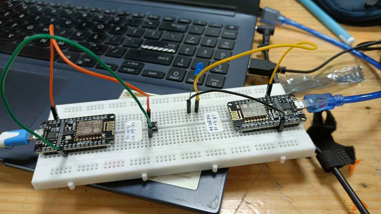
Bi-directional Communication
For Bi-directional communication, I did the same switch to LED, just the difference this time was,
Bidrectional communication
that is, there was no main or secondary Node MCU here, both the Node MCU required the same code. Also
another difference from the
was from the previous one way communication was the switch: Latching Switch. A latching switch stays in its
position (on or off) after being pressed, unlike a momentary switch that returns to its original state. It
"latches" the circuit until pressed again.
Make the connection on both the NodeMCU as:
Connect Switch to GND AND D7 and
Connect LED to GND AND D2
Upload the below code to both the Node MCU.
_6_11zon.png)
//----------------------------------------Load libraries
            #include
            #include
            //----------------------------------------Defines PIN Button and PIN LED.
            #define LED_Pin   D2
            #define BTN_Pin   D7
            //----------------------------------------------------------------------------------------------------------------------------

            //uint8_t broadcastAddress[] = {0xE0, 0x98, 0x06, 0x9C, 0x16, 0x7F}; //--> REPLACE WITH THE MAC Address of your receiver.
            uint8_t broadcastAddress[] = {0x50, 0x02, 0x91, 0xC2, 0xE9, 0x88}; //--> REPLACE WITH THE MAC Address of your receiver.  50:02:91:C2:E9:88
            //---------------------------------------------------------------------------------------------------------------------------

            int BTN_State; //--> Variable to hold the button state.
            int LED_State_Send = 1; //--> Variable to hold the data to be transmitted to control the LEDs.
            int LED_State_Receive; //--> Variable to receive data to control the LEDs on the ESP32 running this code.

            //----------------------------------------Structure example to send data must match the receiver structure

            typedef struct struct_message {
                int led;
            } struct_message_send;

            struct_message send_Data; // Create a struct_message to send data.
            struct_message receive_Data; // Create a struct_message to receive data.
            //---------------------------------------------------------------------------------------------------------------------------

            //++++++++++++++++++++++++++++++++++++++++++++++++++++++++++++++++++++++++++ Callback when data is sent

            void OnDataSent(uint8_t *mac_addr, uint8_t status) {
              Serial.print("\r\nLast Packet Send Status:\t");
              if (status ==0){
                 Serial.println("Delivery success");
              }
              else{
                Serial.println("Delivery fail");
              }
              Serial.println(">>>>>");
            }
            //+++++++++++++++++++++++++++++++++++++++++++++++++++++++++++++++++++++++++++++++++++++++++++++++++++++++++++++++++

            //++++++++++++++++++++++++++++++++++++++++++++++++++++++++++++++++++++++++++ Callback when data is received

            void OnDataRecv(uint8_t * mac_addr, uint8_t *incomingData, uint8_t len) {
              memcpy(&receive_Data, incomingData, sizeof(receive_Data));
              Serial.println();
             // Serial.println("<<<<< Receive Data:");
             // Serial.print("Bytes received: ");
             // Serial.println(len);
              LED_State_Receive = receive_Data.led;
              Serial.print("Receive Data: ");
              Serial.println(LED_State_Receive);
              Serial.println("<<<<<");
              digitalWrite(LED_Pin, LED_State_Receive);
            }
            //++++++++++++++++++++++++++++++++++++++++++++++++++++++++++++++++++++++++++

            //++++++++++++++++++++++++++++++++++++++++++++++++++++++++++++++++++++++++++ VOID SETUP
            void setup() {
              Serial.begin(115200);
              pinMode(LED_Pin, OUTPUT);
              pinMode(BTN_Pin, INPUT_PULLUP);
              WiFi.mode(WIFI_STA); //--> Set device as a Wi-Fi Station
              WiFi.disconnect();

              //----------------------------------------Init ESP-NOW
              if (esp_now_init() != 0) {
                Serial.println("Error initializing ESP-NOW");
                return;
              }

              //----------------------------------------Once ESPNow is successfully Init, we will register for Send CB to
              // get the status of Trasnmitted packet
              esp_now_register_send_cb(OnDataSent);
              esp_now_register_recv_cb(OnDataRecv); //--> Register for a callback function that will be called when data is received
               // Set ESP-NOW Role
              esp_now_set_self_role(ESP_NOW_ROLE_COMBO);
            //----------------------------------------

              //----------------------------------------Register peer
               if (esp_now_add_peer(broadcastAddress, ESP_NOW_ROLE_COMBO, 1, NULL, 0) == 0) {
                Serial.println("Peer added successfully !!");
              } else {
                Serial.println("Failed to add peer !!");
              }
              Serial.println("Initializing push button ...");
            }
            //++++++++++++++++++++++++++++++++++++++++++++++++++++++++++++++++++++++++++

            //++++++++++++++++++++++++++++++++++++++++++++++++++++++++++++++++++++++++++
            void loop() {
              BTN_State = digitalRead(BTN_Pin); //--> Reads and holds button states.

              //----------------------------------------When the button is pressed it will send data to control the LED on the ESP32 Target.
              if(BTN_State == 0) {
                LED_State_Send = !LED_State_Send; // toggle state
                send_Data.led = LED_State_Send;  // send state to the other board
                Serial.println();
                Serial.print(">>>>> ");
                Serial.println("Send data");
                //----------------------------------------Send message via ESP-NOW
              if (esp_now_send(broadcastAddress, (uint8_t *) &send_Data, sizeof(send_Data))==0)
                 {
                  Serial.println("Message sent successfully");
                }
                else {
                  Serial.println("Error sending the data");
                }
                  //----------------------------------------Wait for the button to be released. Release the button first to send the next data.
                while(BTN_State == 0) {
                  BTN_State = digitalRead(BTN_Pin);
                  delay(10);
                }

              }

            }
I uploaded the above code to both the NodeMCU and the
the Code Uploaded successfully.
Learning and Process
During the Networking and Communication week, I attempted to establish communication between two NodeMCU
boards. I successfully uploaded the code onto both boards; however, there was no visible response from the
NodeMCUs.
Initially, I suspected a networking issue, but I observed that even a single NodeMCU, when tested
independently, showed no action. This led me to investigate further and conclude that the problem likely
lies in the code configuration — specifically, how the pins were defined and managed.
One, month later in my IOT lecture, when I got the right code. Both of my Node MCU functioned properly.
I also learnt about the types of communcation that is:
One-way communication: Info flows in one direction only (e.g., TV broadcast).
Bidirectional communication: Info flows both ways (e.g., phone call).
One-to-many communication: One sender, multiple receivers (e.g., public speech or live stream).
Group Assignment
My fab
mates, Mihir
and
Devanshi are
using
NodeMCU for their final project. Thus to refer to a detailed documentation of NodeMCU to NodeMCU refer to
Mihir's
documentation
here.
Project files
Mac Adress Code
Xaio Main Code
Aurdino Secondary Code
Main Push Button Code
Secondary Push Button Code
Bi-derction Push Button Code