Understanding formats: Browse through the data sheet for your microcontroller to interact (with
local input &/or output devices)
Compare the performance and development workflows for other architectures.
Write a program microcontroller development board, to interact with local input
&/or output devices and communicate with remote wired or wireless devices.
Extra credit: use different languages &/or development environments
Extra credit: connect external components to the board
Embedded Programming
Embedded programming is writing software that runs on specialized devices rather than general-purpose
computers. These devices, like washing machines, smartwatches, or car engines, have tiny computers
(microcontrollers or microprocessors) inside them that control how they work. Unlike regular software,
embedded programs are designed to be efficient, reliable, and work with limited memory and power. They
are written in languages like C or Python and directly interact with the hardware to perform specific
tasks, like turning on a motor or reading sensor data.
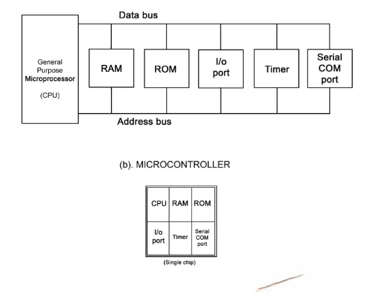
Microcontrollers and microprocessors
Microcontrollers and microprocessors are both types of computing chips, but they serve different.
Microcontroller (MCU): A small, self-contained chip with a processor, memory (RAM & ROM), and
input/output (I/O) ports
all of this built into one unit is a microcontroller. It is designed for specific tasks in embedded
systems, like controlling appliances, cars, or IoT devices. Since everything is integrated, it consumes
less
power and is cost-effective.
Microprocessor (MPU): A more powerful chip that mainly consists of a processor (CPU) without built-in
memory or I/O ports. It relies on external components to function, making it more suitable for complex
tasks like running an operating system on a computer or smartphone. It is faster and more flexible but
requires more power and additional components.
In-build Parts
Processor: You can think of the processor (CPU - Central Processing Unit) as the brain of a
computer or
device.
Memory (RAM & ROM):To learn more about Memory in microcontroller refer to
attatched
Link.
RAM (Random Access Memory) is a temporary memory that stores data while a device is running. It is fast
but loses all data when power is off.
ROM (Read-Only Memory) is a permanent memory that stores essential data, like the system’s startup
instructions (firmware). It retains data even when power is off.
Different Types of Memory in
Microcontroller
Flash Memory: Non-volatile memory used to store the program (firmware) in a microcontroller. Retains
data even when power is off.
SRAM (Static Random Access Memory): Volatile memory used for temporary data storage while the
microcontroller is running. Faster but loses data when power is off.
EEPROM (Electrically Erasable Programmable Read-Only Memory): Non-volatile memory used to store
small
amounts of data that need to be preserved even after power loss, like user settings or calibration
data.
Also it can be rewritten multiple times.
Microcontroller Memory Classification:
Program memory includes different types of ROM:
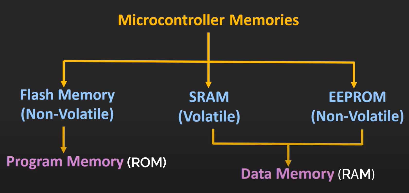
(First Image) Microcontroller Memory Classification. Microcontroller memory is categorized into Flash Memory
(Non-Volatile, used as ROM), SRAM (Volatile,
used as RAM), and EEPROM (Non-Volatile).
Flash Memory stores the program (ROM).
SRAM is used as data memory (RAM) for temporary storage.
EEPROM is another non-volatile storage used for retaining small amounts of data.
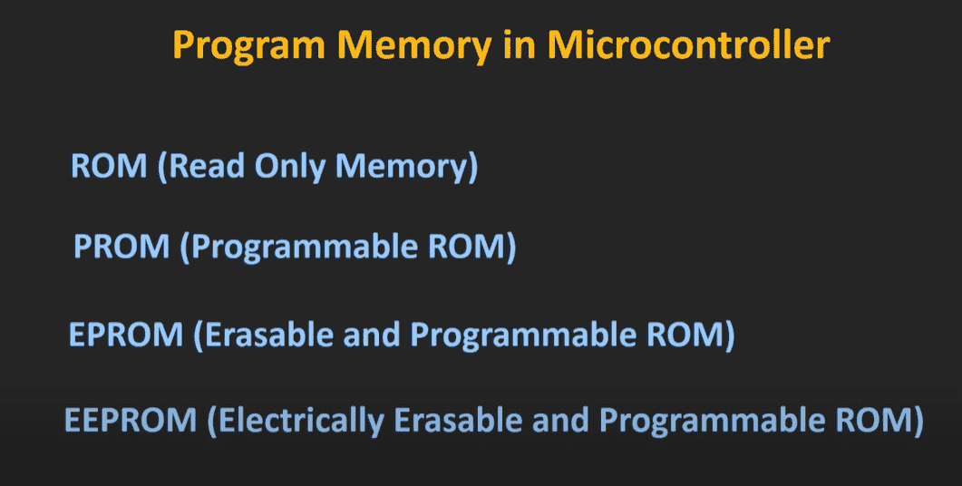
(Second Image) Types of Program Memory in Microcontrollers.
Program memory includes different types of ROM:
ROM (Read-Only Memory) – Pre-programmed, non-modifiable.
PROM (Programmable ROM) – Can be programmed once.
EPROM (Erasable and Programmable ROM) – Erased using UV light and reprogrammed.
EEPROM (Electrically Erasable and Programmable ROM) – Erased and rewritten electrically.
Relevance of EEPROM in Today's Microcontrollers:
EEPROM is crucial in modern microcontrollers for storing non-volatile data, such as calibration
settings, configuration data, and user preferences, without requiring an external storage device. Unlike
Flash memory, EEPROM allows byte-wise erasing and writing, making it suitable for applications that
require frequent updates without wearing out the entire memory block.
Input/output (I/O) ports: I/O refers to how a device interacts with the outside world.
Input: Data or
signals received by a device to process
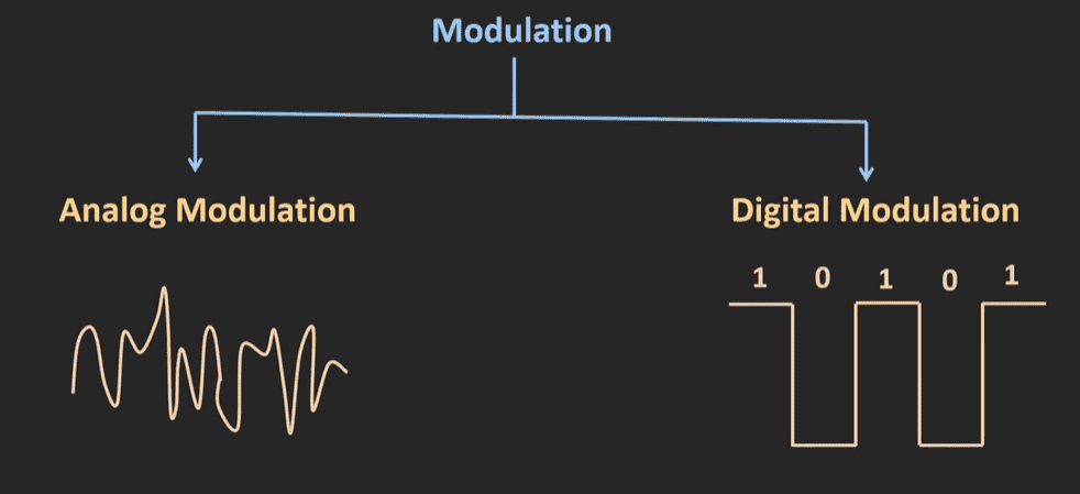
Output: Data or signals sent by a device after processing. Modulation is the process of altering a
signal to transmit data efficiently. Modulation is the process of modifying a signal (message) so it can
be efficiently transmitted over a medium, like radio waves or cables. In microprocessors, modulation
plays a key role in controlling
outputs and communicating with other devices.To learn more about Why Modulation is Required ? Types of
Modulation Explained.
refer to attatched
Link.
Types of modulation in microcontrollers::
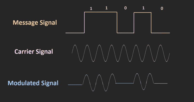
Data Transfer through Modulation:
Key Uses of modulation in microcontrollers:
PWM (Pulse Width Modulation) – Output Control:
Used to control devices like motors, LEDs, and audio signals by varying pulse width.
Helps adjust brightness (LEDs) or speed (motors) without needing extra power.
Common in microcontrollers for efficient power management.
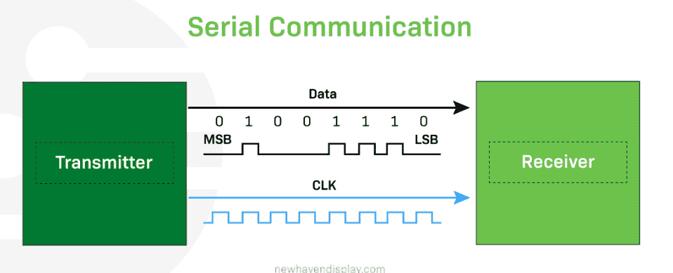
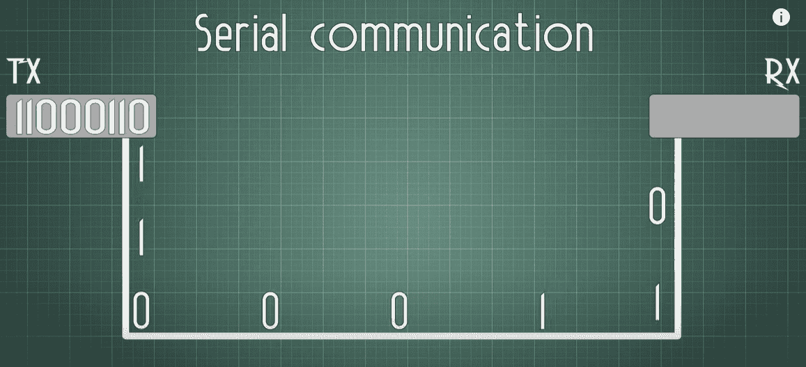
Serial Communication (Modulated Signals) – Data Transfer:
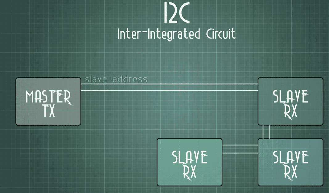
Microprocessors use UART (Universal Asynchronous Receiver-Transmitter), I2C (Inter-Integrated
Circuit), SPI (Serial Peripheral Interface) - Serial
communications to exchange data with sensors, displays, and memory chips.
Serial Communication
I2C Communication
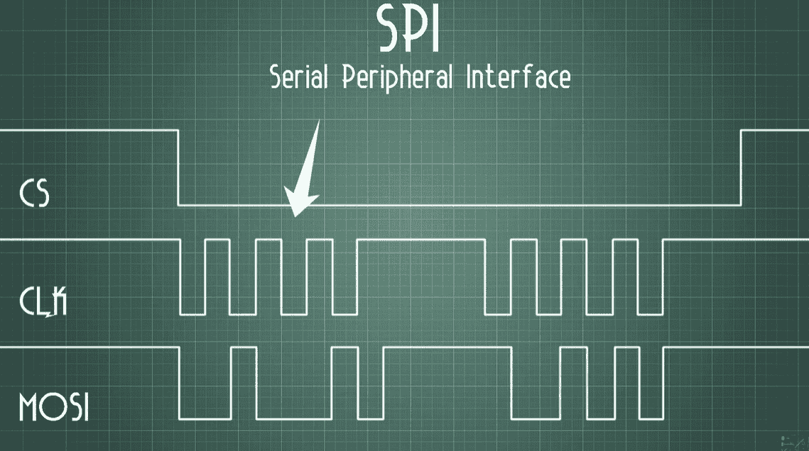
Serial Peripheral Interface
To learn more about
communication Protocols refer to the attatched Link.
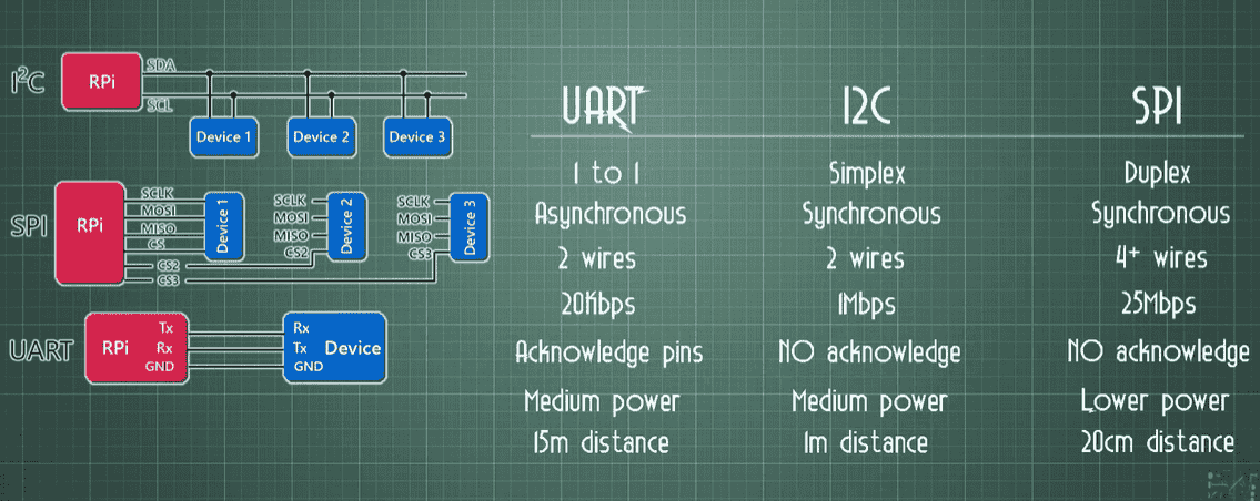
To give a brief of communication Protocols: Imagine you are talking to your friends,
UART (Universal Asynchronous Receiver-Transmitter) – Like texting on a phone.
Uses TX (Transmit) to send and RX (Receive) to get messages.
No clock signal (both sides must agree on the speed beforehand).
Simple but not the fastest.
I2C (Inter-Integrated Circuit) – Like a classroom discussion.
Uses only 2 wires:
SDA (Data Line) → Carries the message.
SCL (Clock Line) → Keeps everyone in sync.
Can connect many devices using the same 2 wires.
Slower than SPI but saves wiring.
SPI (Serial Peripheral Interface) – Like a private hotline.
Uses 4 wires for communication:
MOSI (Master Out, Slave In) → Sends data.
MISO (Master In, Slave Out) → Receives data.
SCLK (Clock) → Keeps timing in sync.
CS (Chip Select) → Chooses which device to talk to.
Fastest communication but needs more wires.
What is a Clock?
Think of it like a conductor in an orchestra, making sure all devices send and receive data at the
right time and simultaneously support the cycles.
I2C & SPI use a clock, while UART does not (which is why UART devices must agree on speed before
talking).
Multiple Wires?
Some protocols (like I2C) use fewer wires to save space.
Others (like SPI) use more wires for faster data transfer.
Group Assignment
Comparison of Toolchains and Development Workflows for ATmega and RP2040
ATmega (used in AVR microcontrollers) and RP2040 (used in Raspberry Pi Pico) are two popular embedded
architectures. Below is a comparative demonstration of their toolchains and development workflows.
ATmega328 Toolchain
The ATmega328 is an 8-bit microcontroller commonly used in Arduino boards (like the Arduino Uno). To
develop software for this microcontroller.
Editor (To write the code):
You can use Arduino IDE, PlatformIO, or a general editor like VS Code.
Programming is usually done in C or C++.
Compiler (To convert human-readable code into machine code)
Compiler(To convert human-readable code into machine code)
The AVR-GCC (GNU Compiler Collection for AVR) is used to compile the code.
AVR stands for Advanced Virtual RISC. It is developed by Atmel (now
part of Microchip Technology). These microcontrollers are designed with a simple and efficient RISC
(Reduced Instruction Set Computing) architecture, allowing them to execute commands quickly and consume
less power.
Linker (To connect different parts of the program)
This arranges the compiled code properly for execution.
Flasher/Programmer (To upload the code to the microcontroller):
The AVRDUDE (AVR Downloader/Uploader) is used to transfer the compiled code (.hex file) into the
ATmega328 chip using an ISP (In-System Programmer) or USB-to-serial converter (like an Arduino
bootloader).
Debugger (To check and fix errors in the program)
The SimAVR simulator or hardware debuggers like Atmel ICE can be used for debugging.
ATmega Development Workflow
🔹 Step 1: Setup Environment
- Install Arduino IDE or AVR toolchain (AVR-GCC, AVRDUDE)
- Choose programming method: USB (Arduino) or ISP (Bare ATmega328)
- Connect hardware (Arduino board or ATmega328 with ISP programmer)
↓
🔹 Step 2: Write Code
- Write program in C/C++ (Arduino IDE or raw AVR)
- Define pin configurations, logic, and functions
↓
🔹 Step 3: Compile Code
- If using Arduino IDE: Click Upload (compiles automatically)
- If using AVR-GCC: Compile manually to generate .hex file
↓
🔹 Step 4: Upload Code
- If using Arduino IDE: Upload via USB
- If using ISP Programmer: Use AVRDUDE to flash the .hex file
↓
🔹 Step 5: Debug & Test
- Use Serial Monitor (UART) for debugging
- Check outputs using LEDs or external debugging tools
↓
🔹 Step 6: Optimize & Finalize
- Optimize power consumption and memory usage
- Burn bootloader (if required)
- Lock fuses to prevent accidental overwriting
↓
END
RP2040 Toolchain
The RP2040 is a dual-core ARM Cortex-M0+ microcontroller developed by Raspberry Pi, commonly used in Raspberry Pi
Pico boards. To develop software for this microcontroller, you need the appropriate toolchain.
Editor (To write the code):
You can use Thonny (for MicroPython), VS Code, or a command-line toolchain.
Programming is usually done in C, C++, or MicroPython.
Compiler (To convert human-readable code into machine code):
For C/C++, the RP2040 uses GCC (GNU Compiler Collection) and CMake to compile the code.
RP2040 is designed by Raspberry Pi and features a flexible I/O system, dual-core processing, and built-in USB
support. It is optimized for embedded applications requiring low power and high performance.
Linker (To connect different parts of the program):
This arranges the compiled code properly for execution and generates the necessary firmware files (.uf2 or .bin).
Flasher/Programmer (To upload the code to the microcontroller):
The RP2040 microcontroller supports drag-and-drop programming. Holding the BOOTSEL button while connecting
via USB mounts the device as a storage drive. The compiled .uf2 file can be copied directly onto it.
Debugger (To check and fix errors in the program):
Debugging can be done using OpenOCD with a hardware debugger like the Raspberry Pi Debug Probe, or by using print
statements and serial debugging via UART.
RP2040 Development Workflow
🔹 Step 1: Setup Environment
- Install Raspberry Pi Pico SDK or use Arduino IDE/MicroPython
- Choose programming language: C/C++, MicroPython, CircuitPython
- Set up development tools: Thonny, VS Code, or command-line toolchain
↓
🔹 Step 2: Write Code
- Write program using CMake (for C/C++) or Python
- Define GPIO, peripherals, and logic
↓
🔹 Step 3: Compile Code
- If using MicroPython: No compilation needed (upload .py script)
- If using C/C++ SDK: Compile using CMake to generate .uf2 file
↓
🔹 Step 4: Upload Code
- Hold BOOTSEL button on RP2040 and connect to PC via USB
- Drag and drop the .uf2 file into the RP2040 storage
- If using MicroPython: Upload script via Thonny or rshell
↓
🔹 Step 5: Debug & Test
- Use Serial Monitor (UART) for debugging
- Check outputs using LEDs, oscilloscope, or print statements
↓
🔹 Step 6: Optimize & Finalize
- Optimize power consumption (sleep modes, low-power optimizations)
- Test performance with different clock speeds and peripherals
- Deploy final firmware and protect memory (if needed)
↓
END
Comparison of Microcontrollers
Feature
RP2040 (Raspberry Pi Pico)
ATmega328 (Arduino Uno)
ESP32
Bit Width
32-bit
8-bit
32-bit
Clock Speed
Up to 133 MHz
Up to 20 MHz
Up to 240 MHz
Power Usage
Low
Very Low
Medium
Ease of Use
Moderate
Easy
Moderate
Programming Tools
ARM GCC, CMake, UF2
AVR-GCC, Arduino IDE
ESP-IDF, Arduino
Datasheet of RP 2040 microcontroller
The RP2040 is Raspberry Pi’s first microcontroller, offering high performance, low cost, and easy use. It
has two powerful cores, lots of built-in memory, and versatile connectivity options. Its unique
Programmable
I/O (PIO) allows flexible control of external devices. It’s great for both professionals and beginners,
thanks to detailed guides, MicroPython support, and an easy-to-use bootloader.
Boot loading is the process of starting up a microcontroller by loading essential software into memory.
The RP2040 has a built-in UF2 bootloader, making it easy to upload new code—just drag and drop files
like a USB drive, no extra tools needed
To Learn more about the RP 2040 microcontroller to the link RP2040
Datasheet.
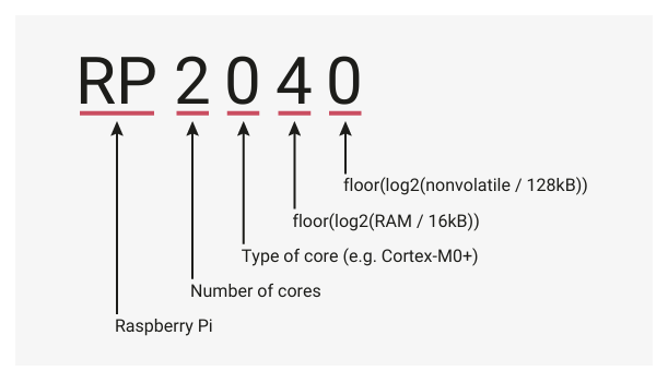
The image explains the naming convention of the RP2040 microcontroller:
RP → Made by Raspberry Pi.
2 → Has 2 processor cores (like having two brains).
0 → Uses Cortex-M0+ core (a type of processor).
4 → Amount of RAM (temporary memory for tasks).
0 → Amount of non-volatile storage (permanent memory).
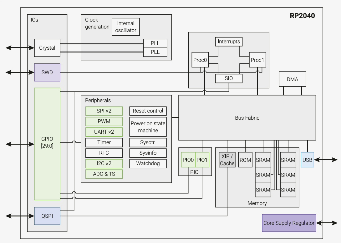
This diagram shows how the RP2040 microcontroller is built and how its different parts work
together:
The RP2040 is a microcontroller designed by Raspberry Pi. It features:
Dual-core Cortex-M0+ processor (efficient and low-power).
264KB RAM (for fast processing).
Flexible I/O options (SPI, I2C, UART, PWM, etc.).
USB 1.1 support (for connecting devices).
No built-in flash memory (external storage needed).
It’s ideal for embedded systems, DIY electronics, and low-power applications.
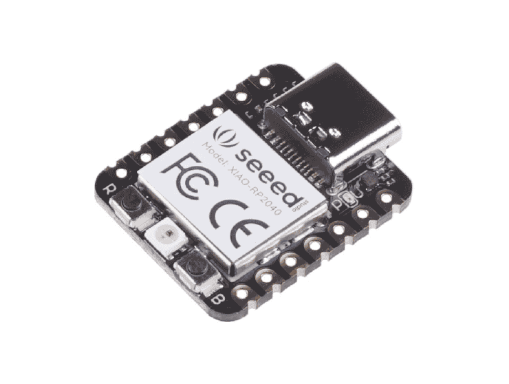
SEEED Arduino XIAO 2040
The SEEED Arduino XIAO 2040 is a compact development board powered by the RP2040 microcontroller from
Raspberry Pi. Designed for embedded electronics projects, its small form factor makes it ideal for
space-constrained applications. The board comes with various built-in peripherals, including GPIO pins,
analog inputs, PWM outputs, UART, SPI, I2C, and USB connectivity. It supports multiple development
environments like the Arduino IDE and CircuitPython, making it beginner-friendly while also catering to
experienced developers for prototyping projects with sensors, actuators, and displays.
To Learn more about the RP 2040 microcontroller to the link,
SEEED Studio XIAO RP2040. Find the extended
datasheet link
here.
I also reffered to Andrian Torres Fab Lab Page to learn an in detailed description of SEEED XIAO 2040.
The SEEED Studio XIAO RP2040 is fully compatible with the Raspberry Pi RP2040 ecosystem, as both share the
same RP2040 chip. It supports multiple programming languages, including C, MicroPython, and CircuitPython,
making it a great choice for beginners and developers alike. Key feature:
Powerful Processor: It has two tiny brains (cores) that can run fast (up to 133 MHz) to handle tasks
efficiently.
Good Memory: It comes with built-in storage (like a small USB drive) to save and run programs smoothly.
Easy to Code: You can program it using MicroPython, Arduino, or CircuitPython, which are
beginner-friendly coding languages.
Simple to Use: Designed to fit easily on a breadboard (a board for connecting wires and components) and
has no extra parts on the back, easier to attach to projects.
Super Small: It’s as tiny as your thumb (20x17.5mm), making it perfect for wearable gadgets or small
projects.
Connects to Many Things: It has several pins to attach sensors, LEDs, motors, and displays, allowing
you to create interactive projects.
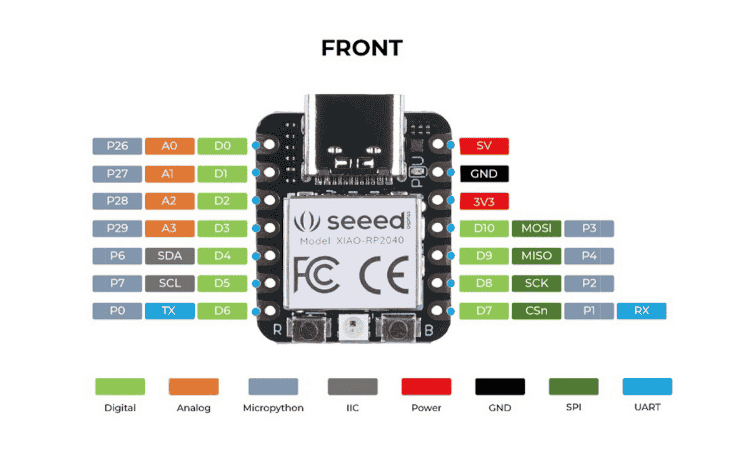
The first image (Front View) displays the pin configuration. It highlights the GPIO (digital and
analog pins), power pins (5V, 3.3V, GND), communication interfaces (SPI, I2C, UART), and MicroPython
compatibility. These labeled pins allow connections to sensors, displays, and other peripherals.
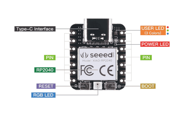
The second image (Back View) shows important onboard features, including the Type-C interface for
programming and power, RP2040 microcontroller, reset button, RGB LED, power LED, user LED
(multi-color), and boot button. These features help in debugging, programming, and status
indication.
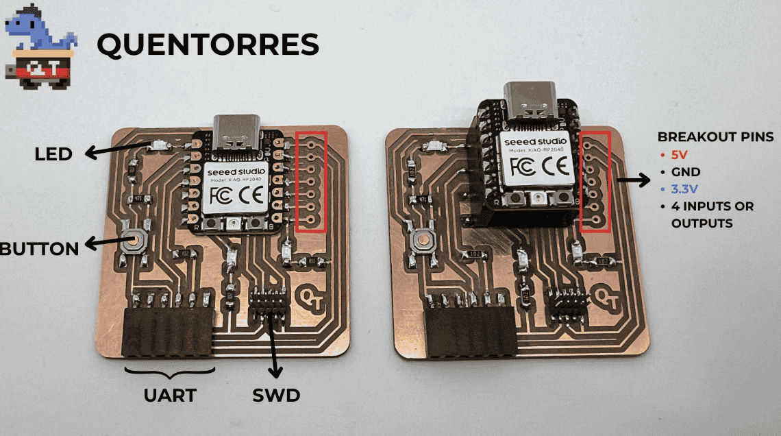
Quentorres Board
The Quentorres board is a development board designed to program the new AVR Series 1 and 2
microcontrollers. It was first created during the 2024 Instructors Bootcamp in León by Quentin Bolsée
and later redesigned by Adrián Torres. The board includes a button and an LED, making it ideal for
learning and practicing programming in C, Rust, Go, MicroPython, and more. Additionally, it features
breakout pins, allowing users to connect external components like sensors and motors for expanded
functionality. This makes the Quentorres a versatile and beginner-friendly tool for experimenting with
AVR microcontrollers.
The first image provides a SEEED Studio XIAO RP2040 microcontroller with its pinout details
labelling,
categorizing the pins into analog, digital, power,
I2C, SPI, and UART functions, helping in circuit integration.
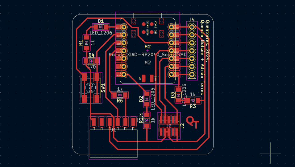
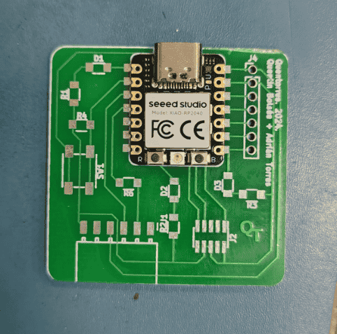
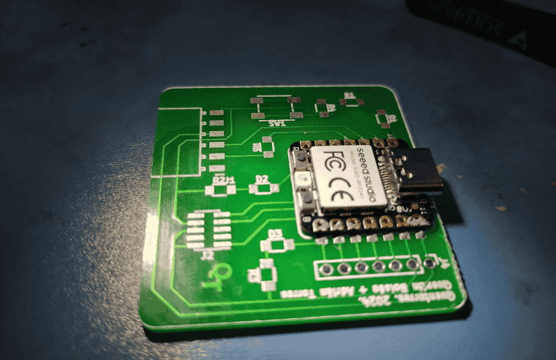
PCB (Quentorres) designed around the SEEED Studio XIAO RP2040. The third image shows the physical PCB
with labeled breakout pins, a button, LED, UART, and SWD interface, indicating its debugging and
interfacing capabilities.
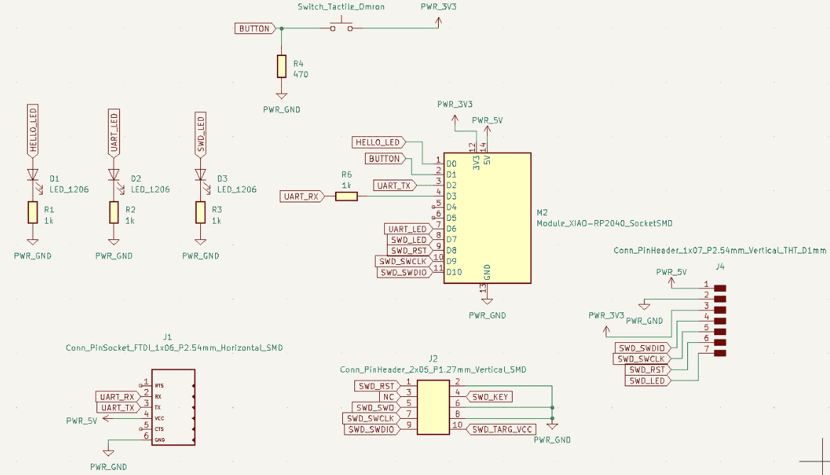
The image shows the schematic diagram of the Quentorres board, which is designed around the SEEED
Studio XIAO RP2040 microcontroller. It includes various components such as: LED indicators, UART
communication, Power connections (3.3V, 5V, and GND).
I referred to this schematic while manually adding code and simulating the XIAO SEEED Studio
Quentorres board, ensuring proper pin mapping and component functionality.
Programming the microcontroller development board
To program the microcontroller development board, I explored SEEED Studio, a well-known platform
offering
various development boards, modules, and sensors for embedded systems and IoT projects. SEEED Studio
provides extensive documentation, libraries, and resources to assist in programming microcontrollers
like ATtiny85, Arduino, ESP32, and Raspberry Pi.
I referred to the SEEED
Studio website to understand the programming process, including setting up the
development environment, selecting the correct board, and uploading code using platforms like
Arduino
IDE or PlatformIO. The website also offers pre-built libraries and sample codes to help streamline
development.
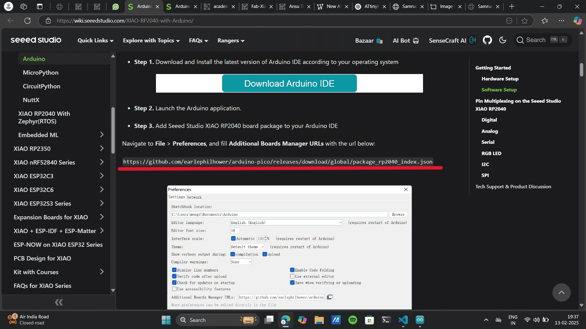
Process of setting up the SEEED Studio XIAO RP2040 board in Arduino IDE. This setup allows
programming and simulating SEEED Studio microcontrollers within the Arduino environment.
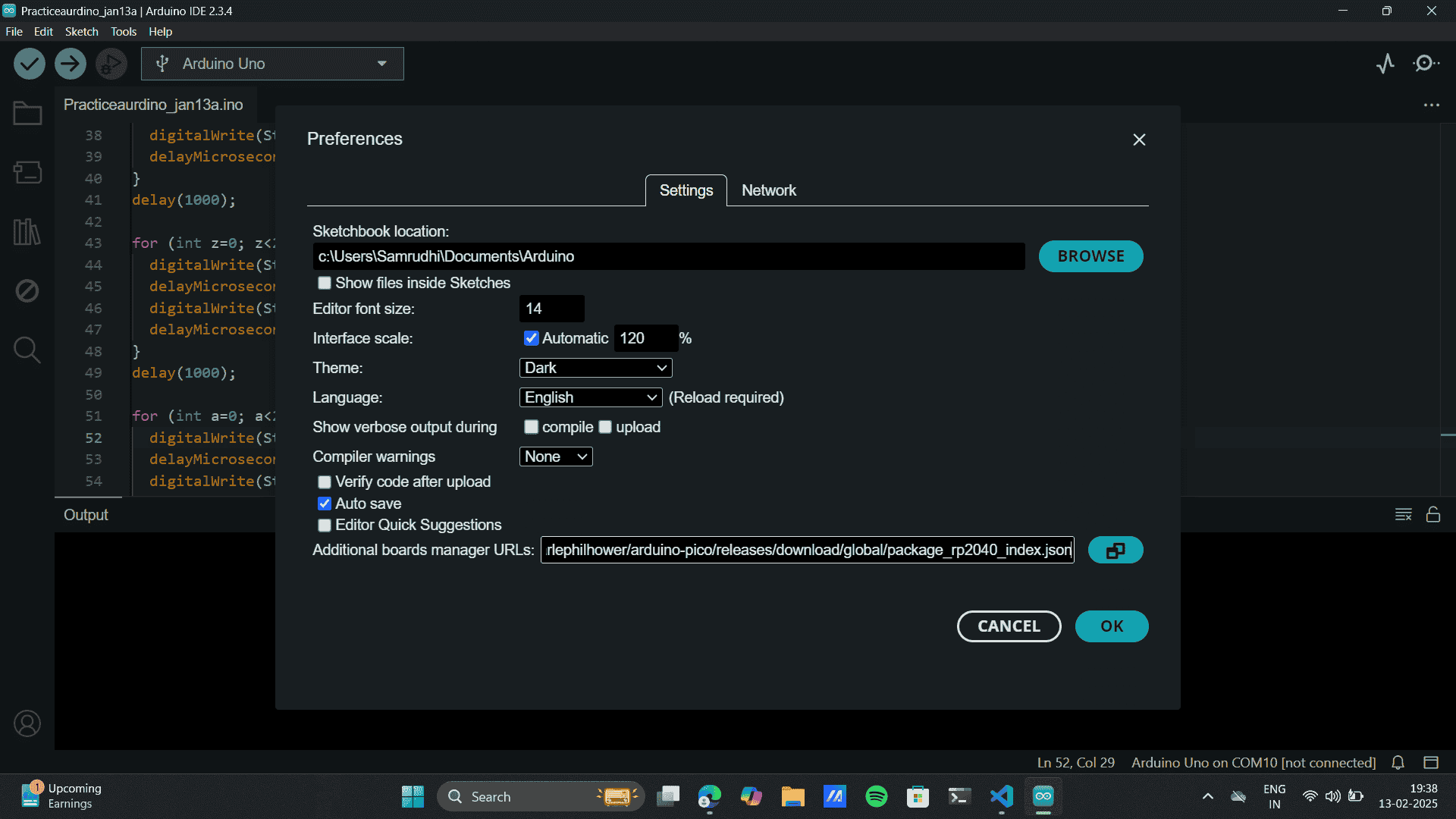
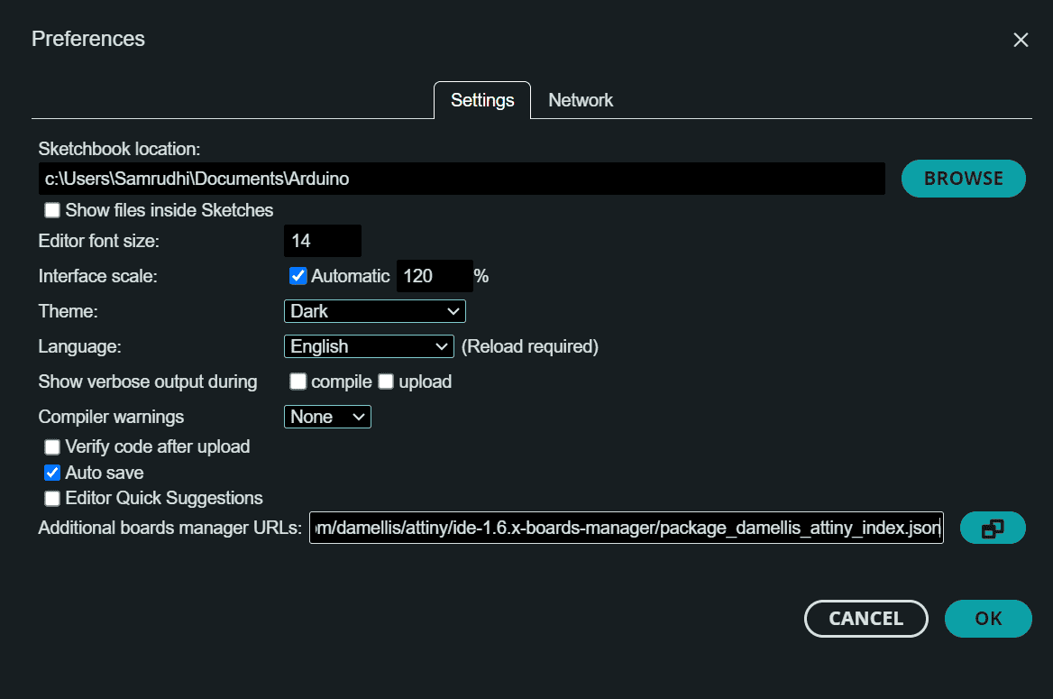
Adding the board package by navigating to File > Preferences in Arduino IDE.
Entering the Additional Boards Manager URL from the SEEED Studio documentation.
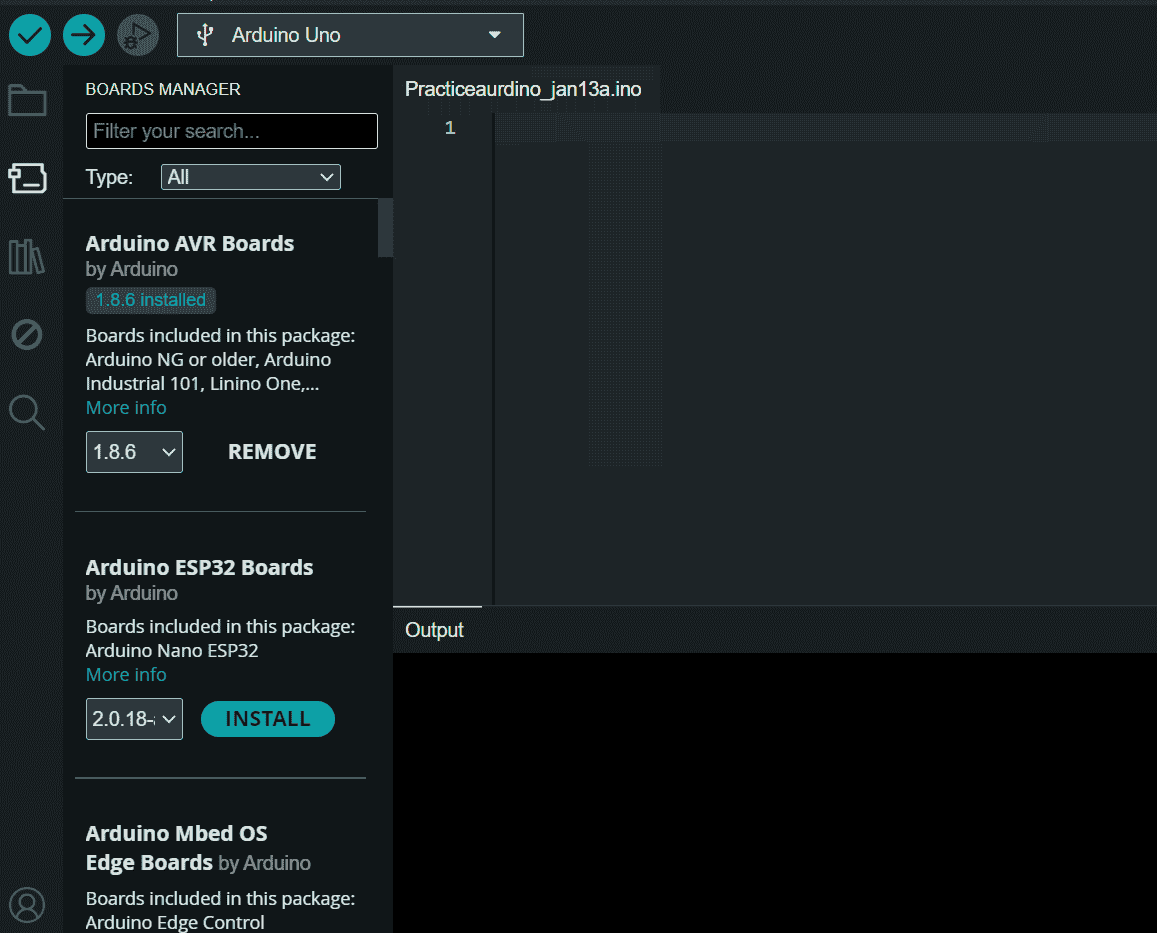
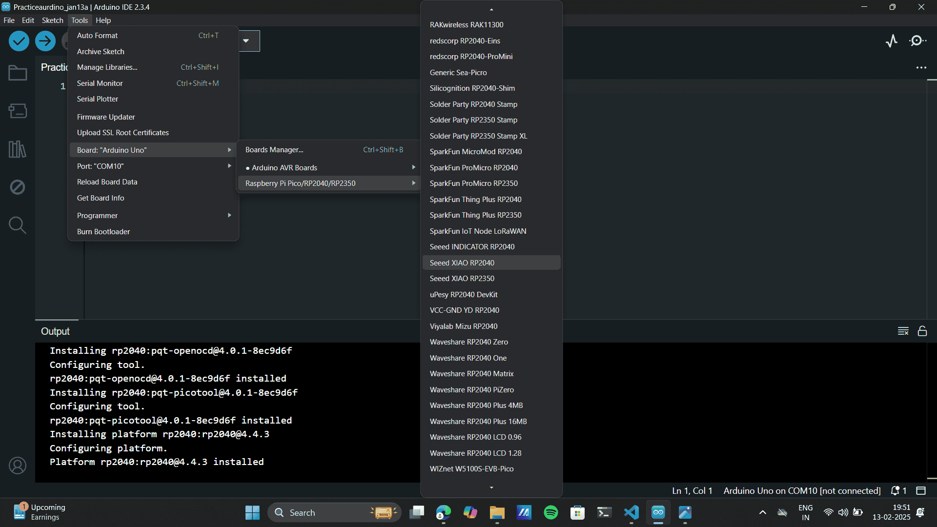
Open the Boards Manager:
In the Arduino IDE, click on the Boards Manager icon (left sidebar).
Alternatively, go to Tools > Board > Boards Manager.
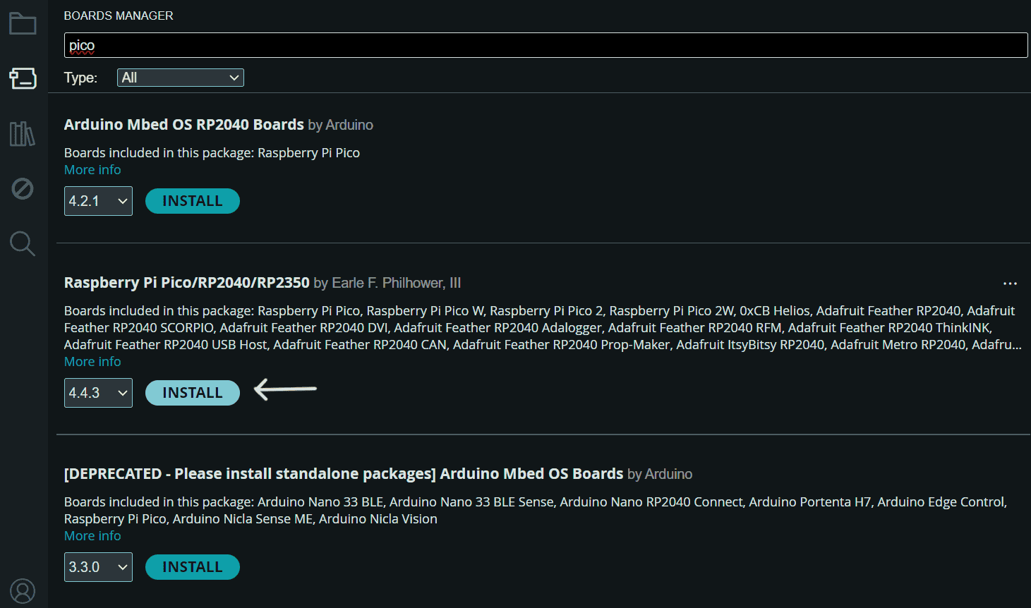
Search for "Pico" and type "Pico" in the search bar.
Select the Correct Package:
Choose "Raspberry Pi Pico/RP2040/RP2350".
This package supports Raspberry Pi Pico, Pico W, Pico 2, and other RP2040-based boards.
Install the Package.
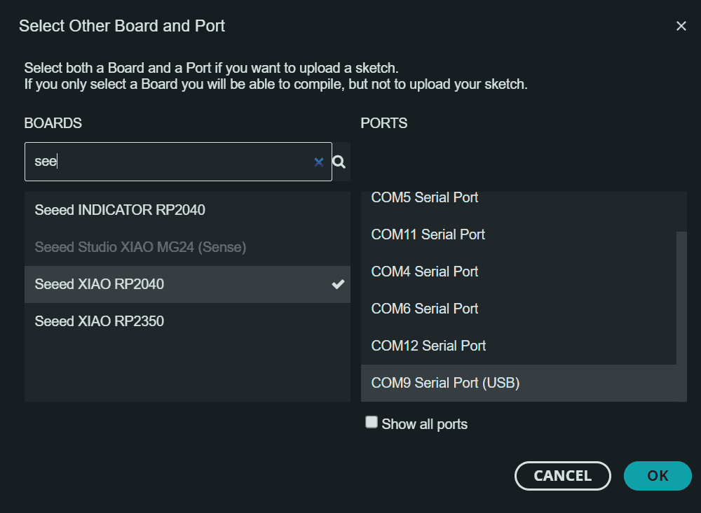
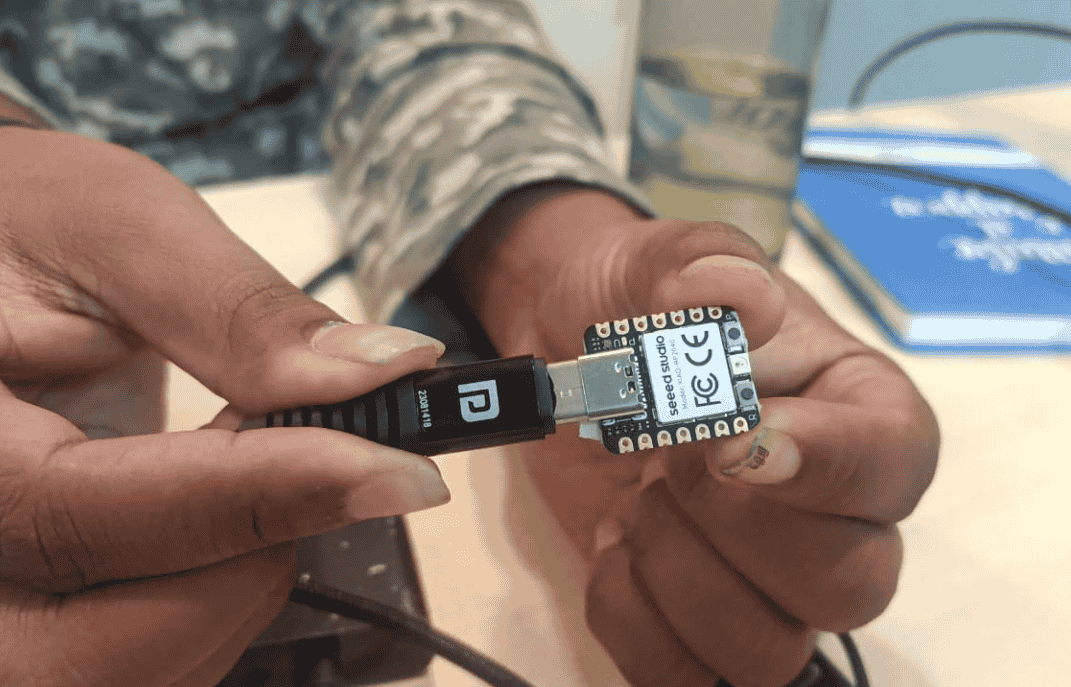
In Arduino IDE, select SEEED XIAO RP2040 as the board and choose COM9 Serial Port (USB) to upload
the
sketch successfully. Attatch the XIAO-RP2040 to an USB Port
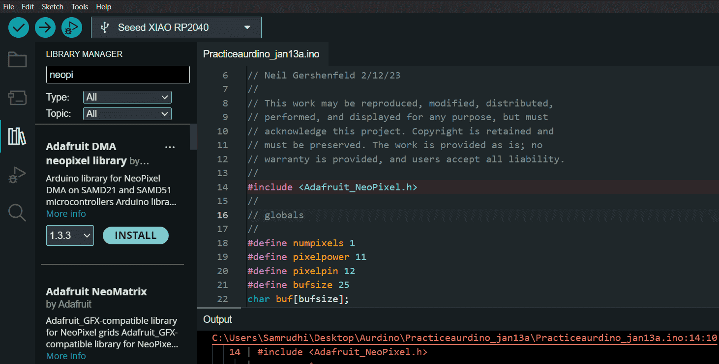
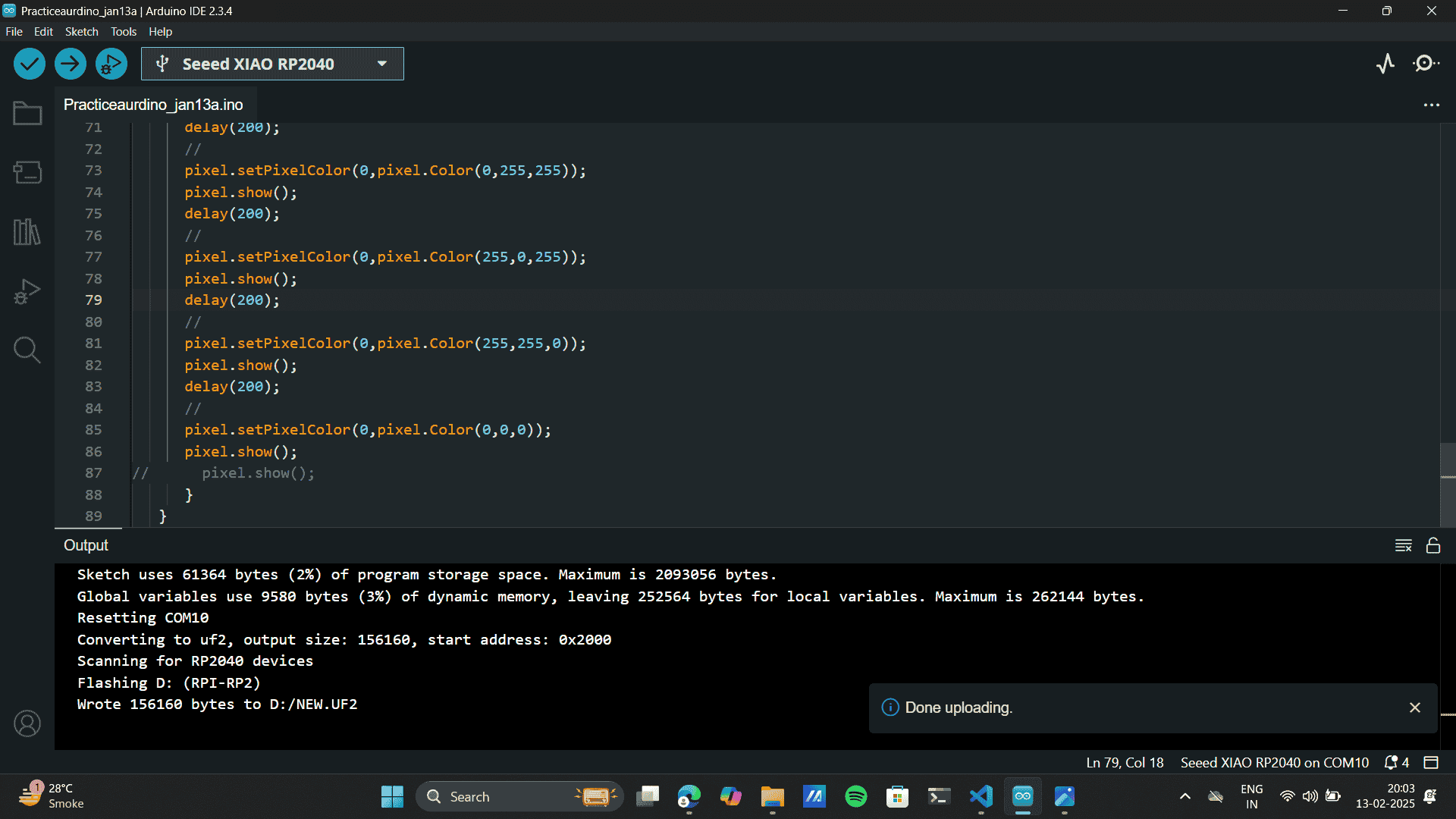
Load up the Blink program from Neil's page. The code is sourced from Neil's reference link, ensuring
compatibility with the selected board.
Blink for RP2040, and upload the code to the Aurdino IDE.
The code used above is as follows:
            //
            // hello.RP204-XIAO.blink-echo.ino
            //
            // Seeed XIAO RP2040 blink and echo hello-world
            //
            // Neil Gershenfeld 2/12/23
            //
            // This work may be reproduced, modified, distributed,
            // performed, and displayed for any purpose, but must
            // acknowledge this project. Copyright is retained and
            // must be preserved. The work is provided as is; no
            // warranty is provided, and users accept all liability.
            //
            #include
            //
            // globals
            //
            #define numpixels 1
            #define pixelpower 11
            #define pixelpin 12
            #define bufsize 25
            char buf[bufsize];
            int count=0;
            //
            // setup
            //
            Adafruit_NeoPixel pixel(numpixels,pixelpin,NEO_GRB+NEO_KHZ800);
            void setup() {
               Serial.begin();
               pixel.begin();
               pinMode(pixelpower,OUTPUT);
               digitalWrite(pixelpower,HIGH);
               }
            //
            // main loop
            //
            void loop() {
               char chr;
               //
               // check for a char
               //
               if (Serial.available()) {
                  //
                  // read, save, and send char
                  //
                  chr = Serial.read();
                  buf[count] = chr;
                  count += 1;
                  buf[count] = 0;
                  if (count == (bufsize-1))
                     count = 0;
                  Serial.print("hello.RP2040-XIAO.blink-echo.ino: you typed ");
                  Serial.println(buf);
                  //
                  // blink LED red green blue white black
                  //
                  pixel.setPixelColor(0,pixel.Color(255,0,0));
                  pixel.show();
                  delay(200);
                  //
                  pixel.setPixelColor(0,pixel.Color(0,255,0));
                  pixel.show();
                  delay(200);
                  //
                  pixel.setPixelColor(0,pixel.Color(0,0,255));
                  pixel.show();
                  delay(200);
                  //
                  pixel.setPixelColor(0,pixel.Color(255,255,255));
                  pixel.show();
                  delay(200);
                  //
                  pixel.setPixelColor(0,pixel.Color(0,255,255));
                  pixel.show();
                  delay(200);
                  //
                  pixel.setPixelColor(0,pixel.Color(255,0,255));
                  pixel.show();
                  delay(200);
                  //
                  pixel.setPixelColor(0,pixel.Color(255,255,0));
                  pixel.show();
                  delay(200);
                  //
                  pixel.setPixelColor(0,pixel.Color(0,0,0));
                  pixel.show();
            //      pixel.show();
                  }
               }
An error occured because the Adafruit_NeoPixel library was missing. To fix this,I install the
Adafruit
NeoPixel library via the Library Manager in the Arduino IDE. After installation, restart the IDE if
necessary and try compiling again.
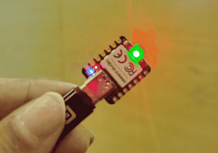
Successfully, Uploaded the Code
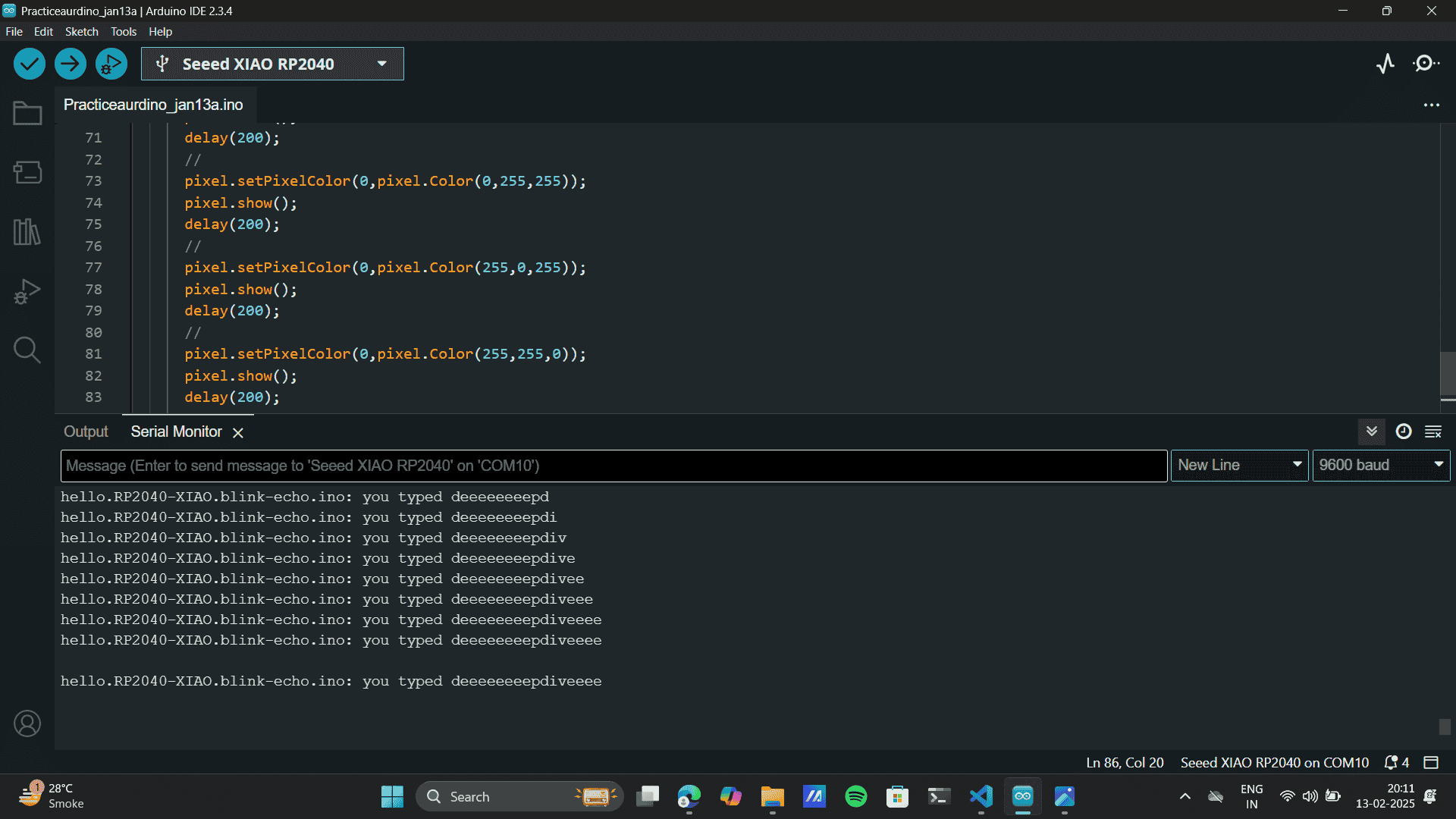
Ctrl + Shift + M opens the Serial Monitor in Arduino IDE. The Serial Monitor displays messages from
the
microcontroller, allowing you to debug and interact with the code in real time.
Here the code maps the number of letters typed in "deep dive" to the number of LED color changes and
blinks. The more letters typed, the more LED state transitions occur. This means each character
input
increases the frequency or sequence of color changes and blinks in the connected LED strip.
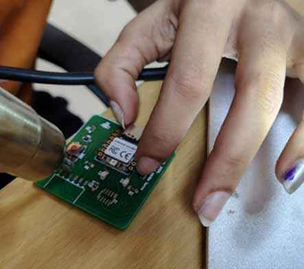
Connecting XIAO-RP2040 and other components to the Quentorres Board.
I soldered the components onto the Quentorres PCB, which includes connecting the XIAO RP2040
microcontroller.This is the Quentorres Board designed by Adrian Torres. Here’s a detailed step-by-step guide:
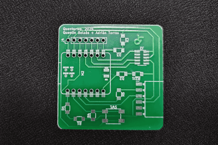
Printed circuit board (PCB) before any components are soldered. The PCB has a green solder mask with white
silkscreen markings that indicate where components will be placed.
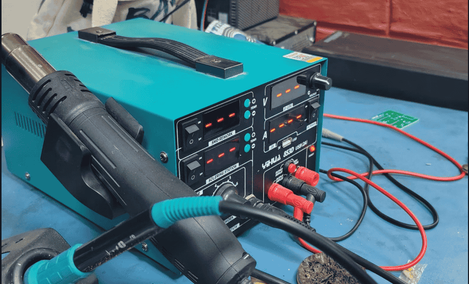
Soldering station, including a soldering iron, power supply, and necessary tools for assembling the PCB.
Soldering materials like a spool of solder wire and flux, which help in making clean and strong electrical
connections.
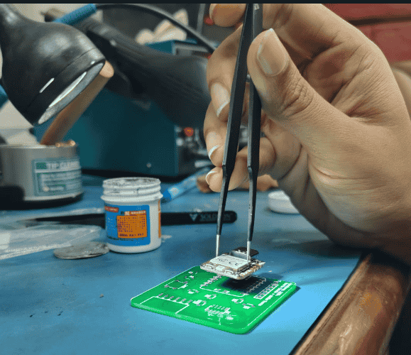
The process of soldering a surface-mount component onto the PCB using tweezers and a soldering iron.
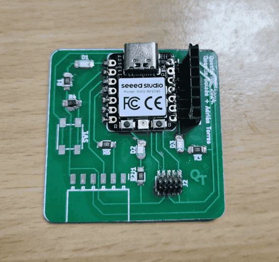
The progress in the assembly, with the XIAO-RP2040 component already soldered onto the PCB.
I carefully worked on the PCB, ensuring proper placement of components.
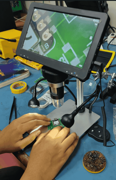
I checked the PCB being examined under a digital microscope to check for soldering quality and
potential errors.
Partially Assembled PCB
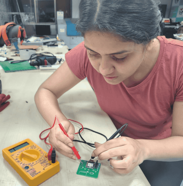
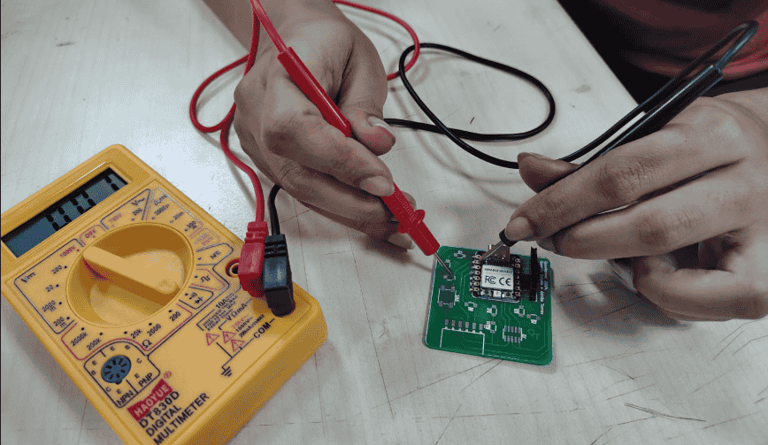
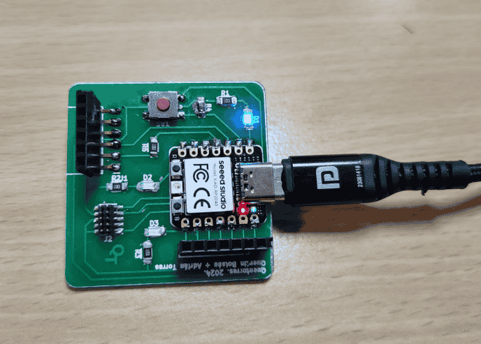
Final Assembly & Testing
Electrical testing using a multimeter, verifying correct connections and circuit functionality.
Soldered the XIAO RP2040 on the Quintoress Board.
Soldering Components like LED, resistors and switch.
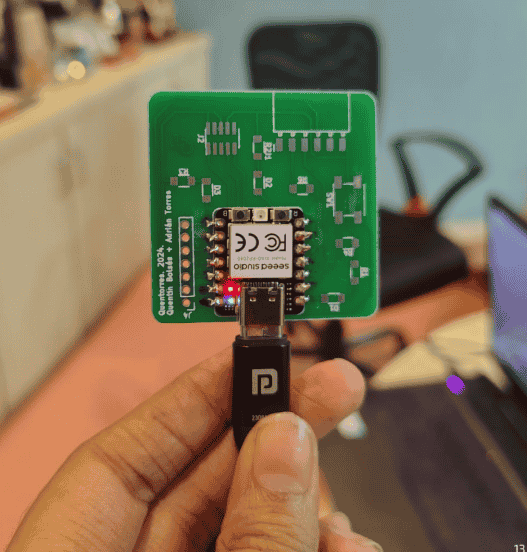
Final Assembly.
The circuit is successfully operational.
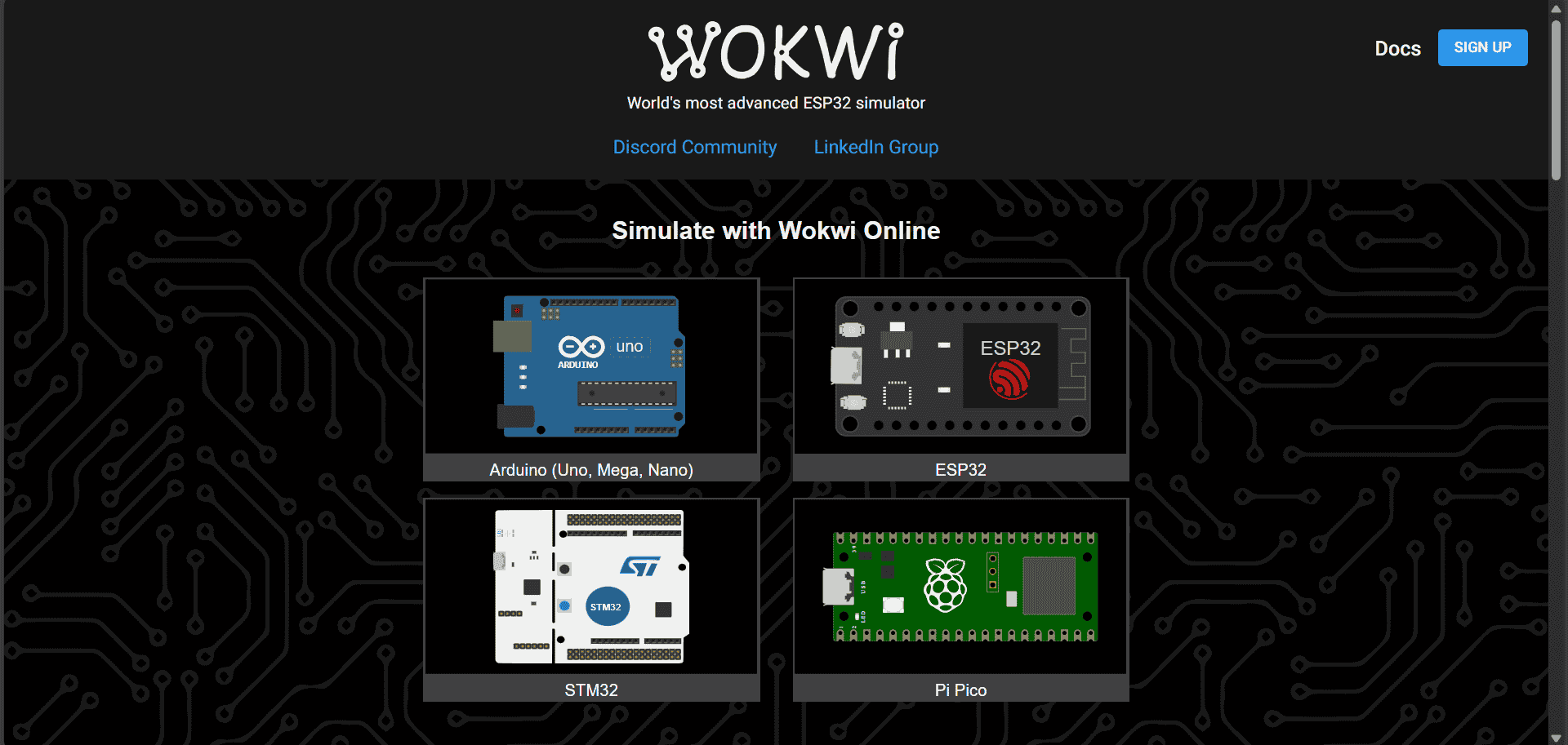
Write a program for a microcontroller, and simulate its operation
Wokwi is an online simulator for microcontrollers like Arduino, ESP32, and Raspberry Pi Pico, allowing
users to build and test circuits virtually before implementing them on hardware. It supports various
components, including the HC-05 Bluetooth module, ATtiny85, sensors, and displays, while enabling coding
in C++, MicroPython, and CircuitPython. Wokwi also provides debugging tools to troubleshoot errors in
connections and code efficiently. I used Wokwi to build my connection for an ATtiny85 blink code,
allowing me to simulate and refine the setup before working with the physical components.
Click here to explore the website.
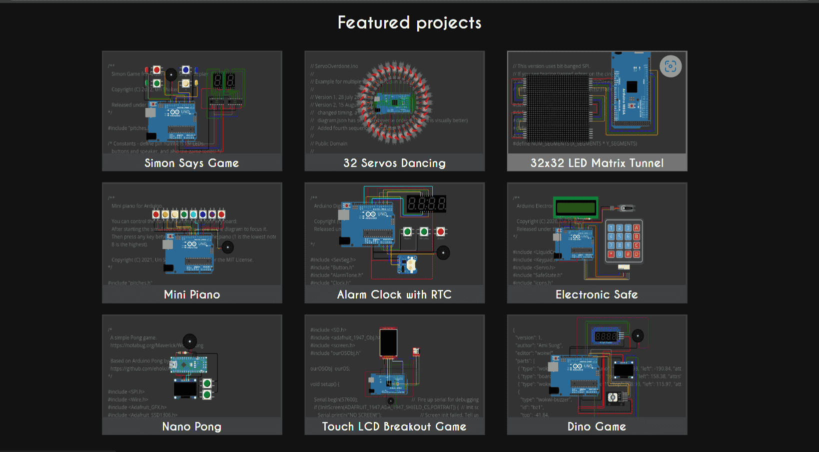
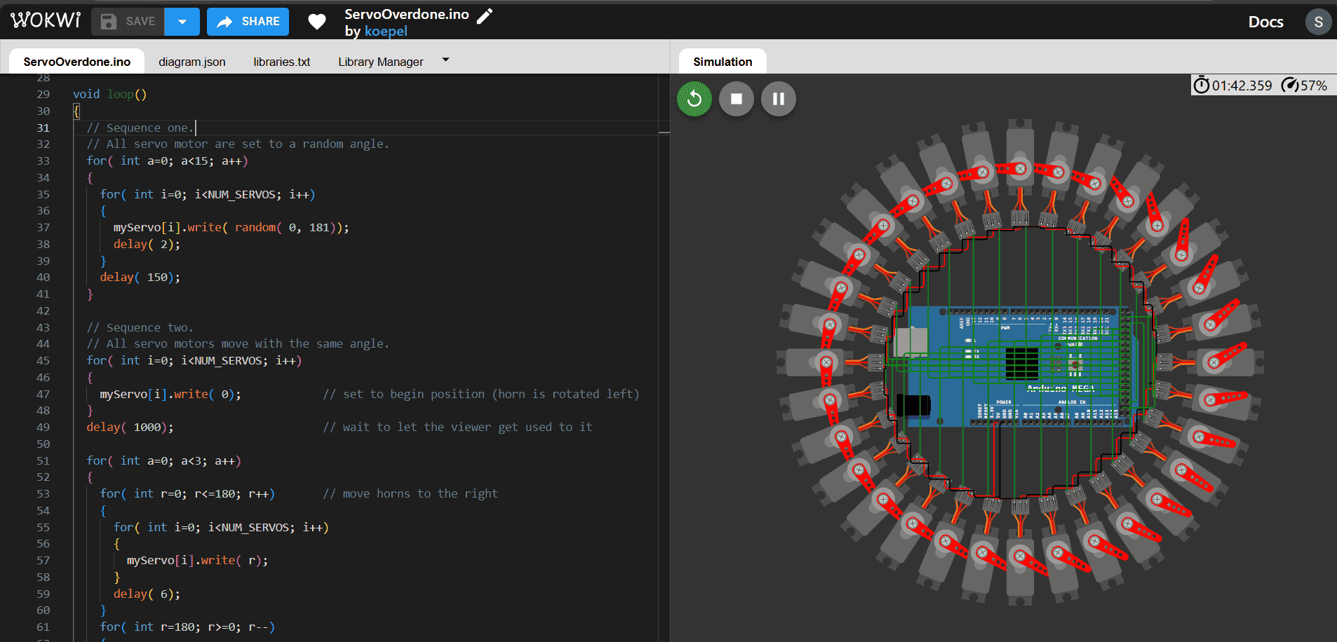
I explored some featured projects on Wokwi and chose an Arduino-based servo motor project to understand
motor control and further experiment with microcontroller applications to learn the basic code language
and simulator techniques.
Wokwi featured projects
Arduino-based servo motor project.
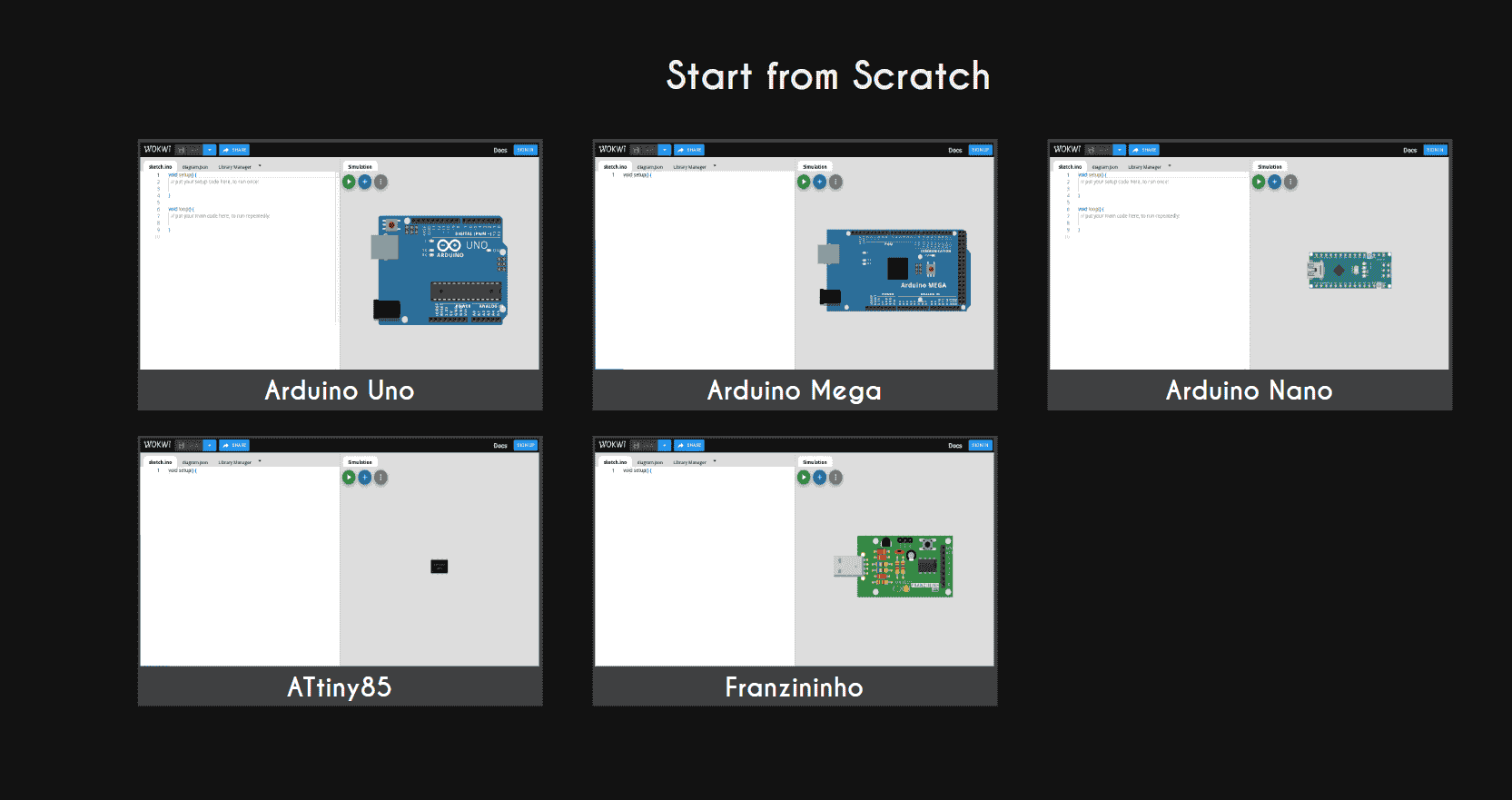
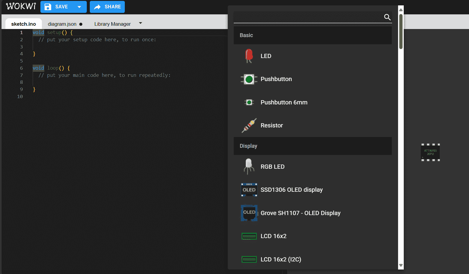
I went to the "Start from Scratch" section in Arduino on Wokwi
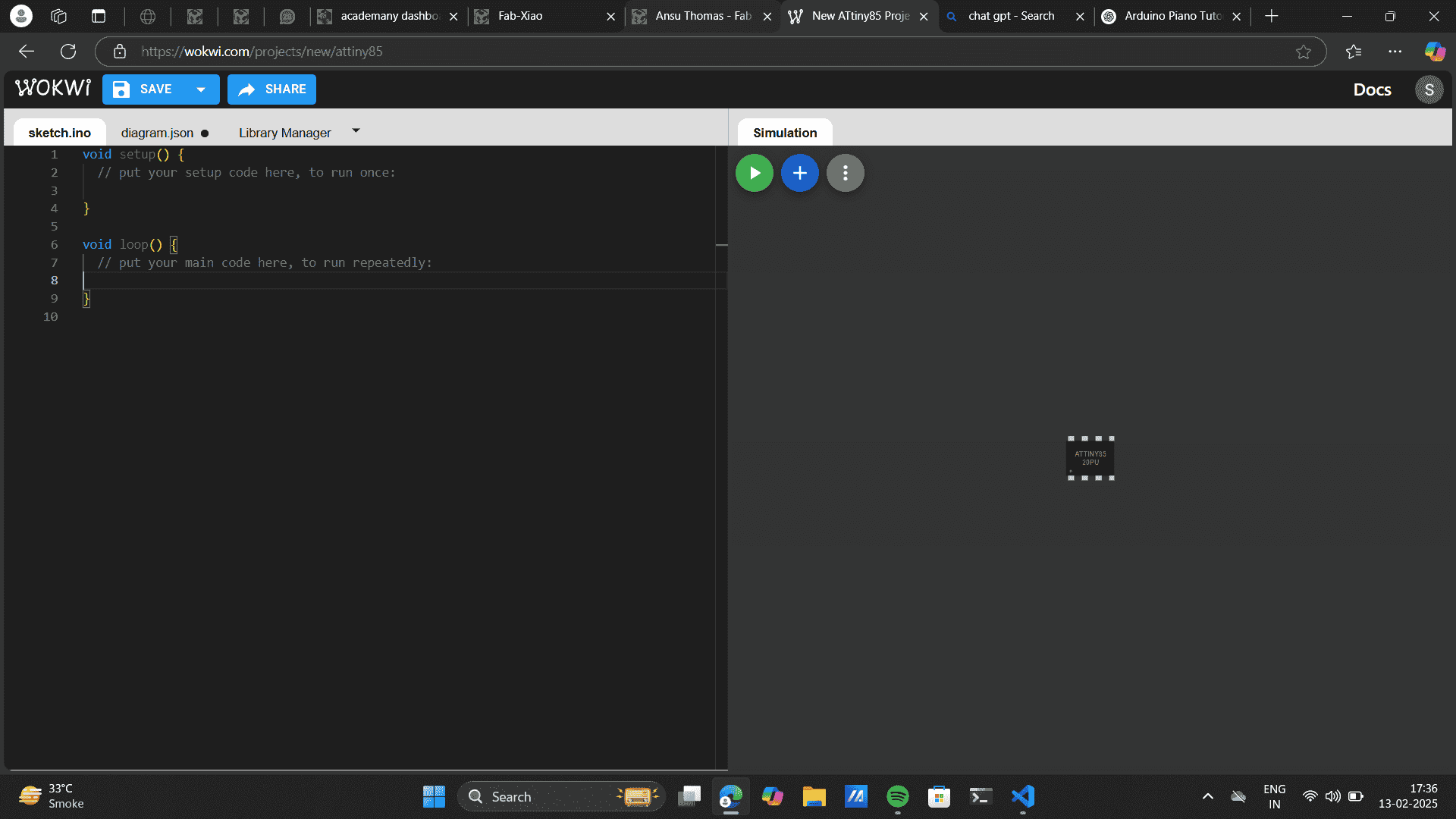
I opened the ATtiny85 board to explore its features and build my project.
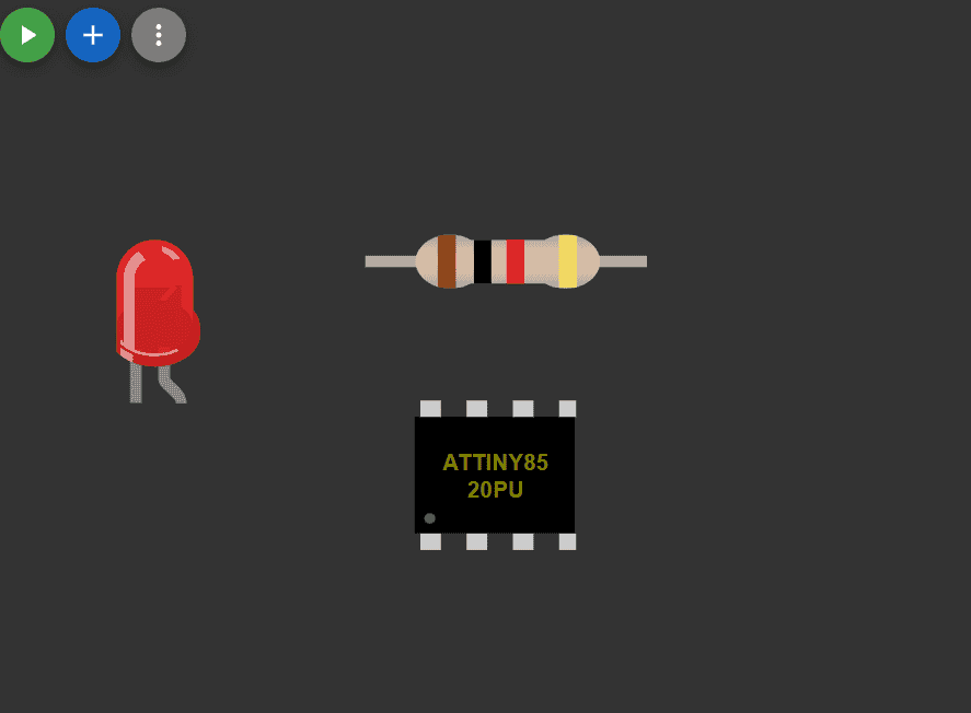
Wokwi provides an option to add various components.
You can easily drag and drop components.
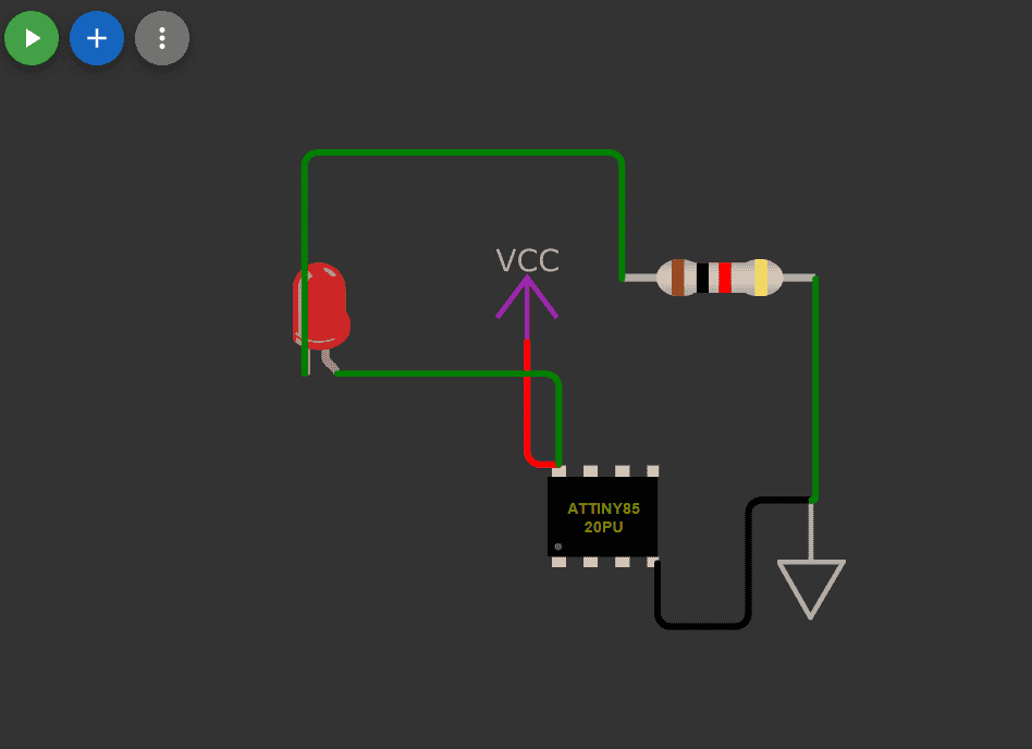
I wrote my own code for blinking an LED using the ATtiny85 and also used ChatGPT to verify it by
prompting: "Generate a code for blinking an LED using ATtiny85, along with a schematic and pin
configuration." After confirming the setup, I added the necessary components in Wokwi and successfully
simulated the connection.
Connect the to the ATtiny85 or other microcontrollers
I wrote my own code for blinking an LED.
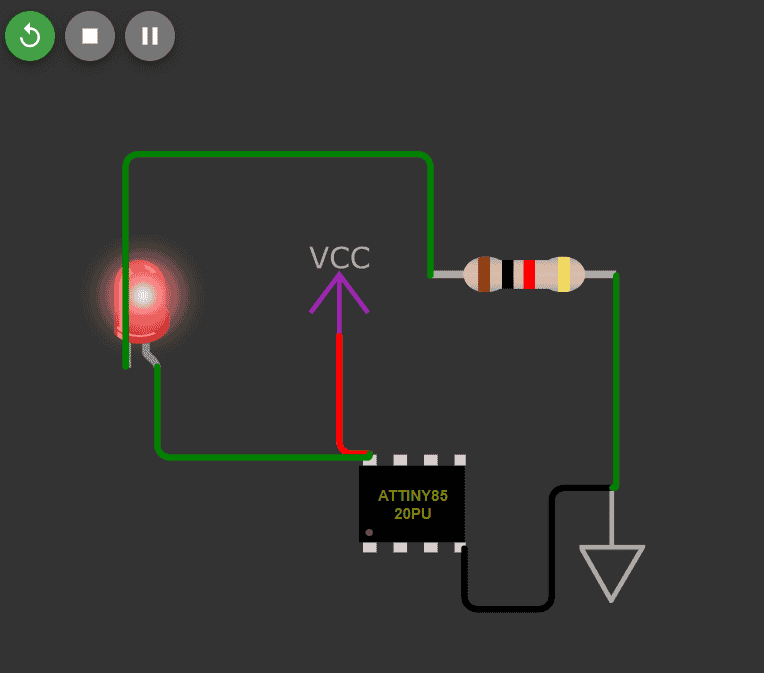
Successfully simulated the connection.
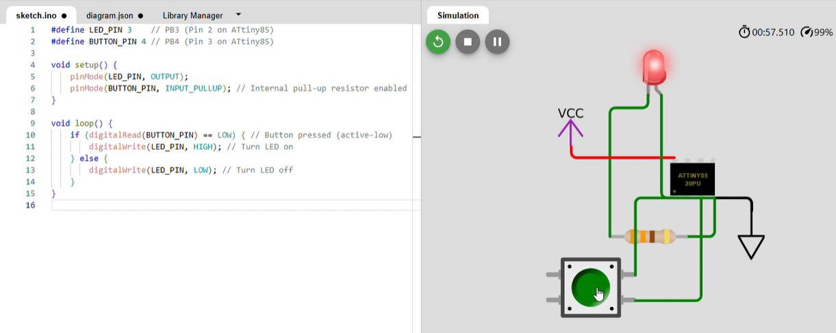
We successfully simulated the connection, confirming the system's functionality. Initially, we
tested
LED blinking, which served as a basic output simulation. To further explore input-output
interactions,
we implemented a button-controlled LED simulation, demonstrating direct user input response.
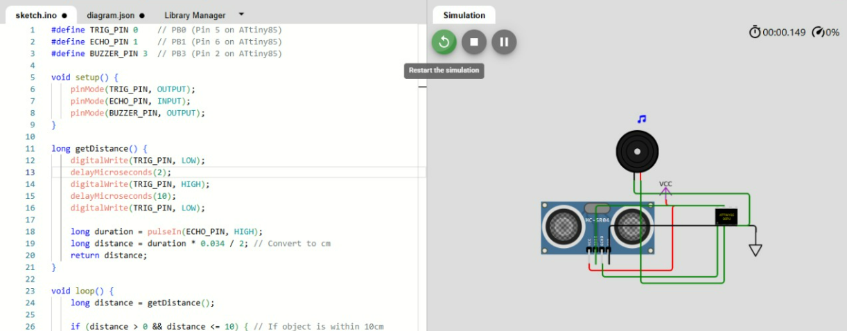
Building on this, we integrated an ultrasonic sensor, which allowed for distance-based activation,
and
paired it with a sound output module. This setup enabled a more complex interaction where the system
responded dynamically to changes in the environment. These simulations helped us validate the
connectivity, responsiveness, and potential real-world applications of the components.
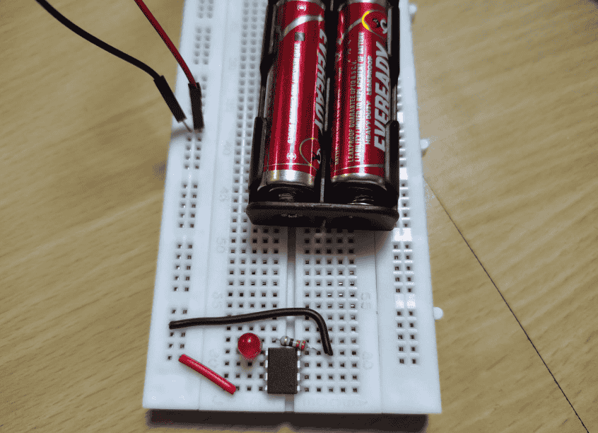
From Simulation to Reality
Building an ATtiny85 LED Circuit. With a solid understanding of the simulations, we
moved on to building a practical circuit using the ATtiny85 microcontroller. Our objective was to
implement a functional LED blinking system, translating our virtual simulations into a
real-world working model.
Step 1: The components required to build this ATtiny85 LED circuit are:
ATtiny85 microcontroller
Breadboard
LED
Resistor (likely 330Ω - 1kΩ for LED current limiting)
Jumper wires
Battery holder (for power supply)
AA batteries (2x Eveready, providing 3V power)>
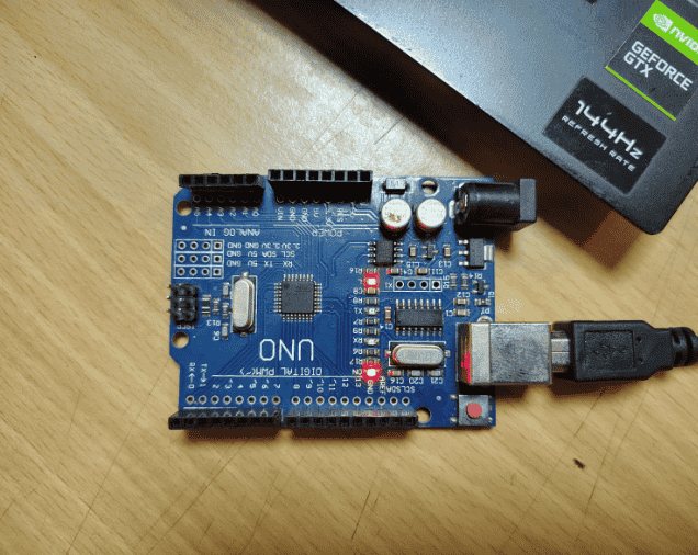
Step 2. The ATtiny85 requires a power connection to function
Typically 3V–5V Power, which can be supplied
using batteries or an external power source. To program the ATtiny85, an Arduino board is used as an
In-System Programmer (ISP).
ISP (In-System Programming) is a method of programming microcontrollers while they are installed in a
circuit. It allows firmware updates and code uploads without removing the chip, using a programmer
(e.g., an Arduino as ISP) via SPI communication.
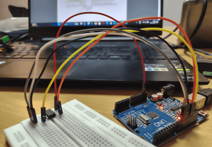
Connect the Aurdino to the device.
translating our virtual simulations into a
real-world working model.
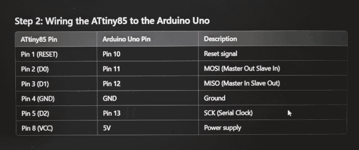
Connecting the ATtiny85 to the Arduino via SPI (MISO, MOSI, SCK) along with power (VCC, GND) and a reset
pin. For which I used ChatGPT
to understand the Pin configuration.ChatGPT command: Generate a code for blinking a led add a push button
using attiny85 also give a schematic an dpin
confirmation.
Building this ATtiny85 LED circuit by using Aurdino as the ISP and power supplier.
Step 3: Bootloading and Programming ATtiny85 Using Arduino as ISP.
Bootloading is the process of installing a small program (bootloader) onto a microcontroller, allowing
it to be programmed via an external interface like USB or ISP. It initializes the hardware, sets up
clock configurations, and enables future code uploads without needing a dedicated programmer.
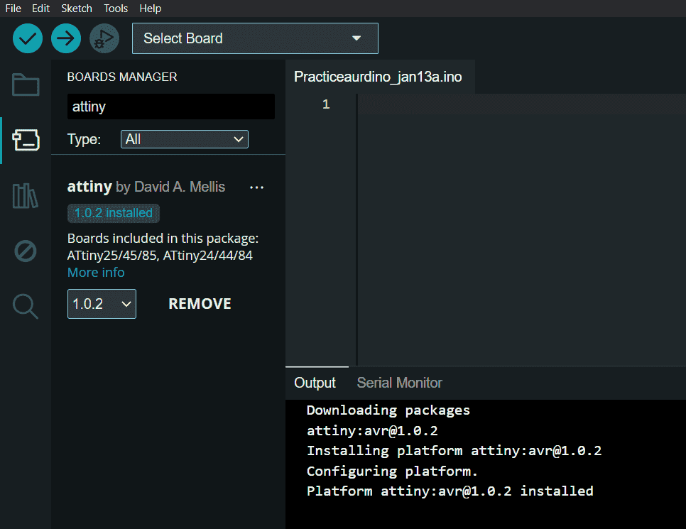
Setting Up ATtiny85 Board Manager:
Open Arduino IDE and go to File > Preferences.
Under Additional Board Manager URLs, add the GitHub link that provides the ATtiny85 board
definitions.
Navigate to Tools > Board > Boards Manager, search for ATtiny, and install the ATtiny board
library.
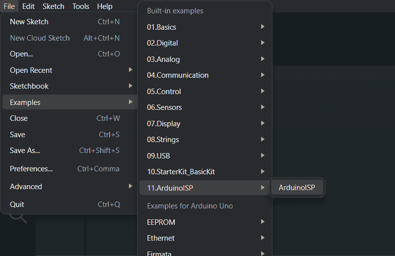
Setting Up Arduino as ISP:
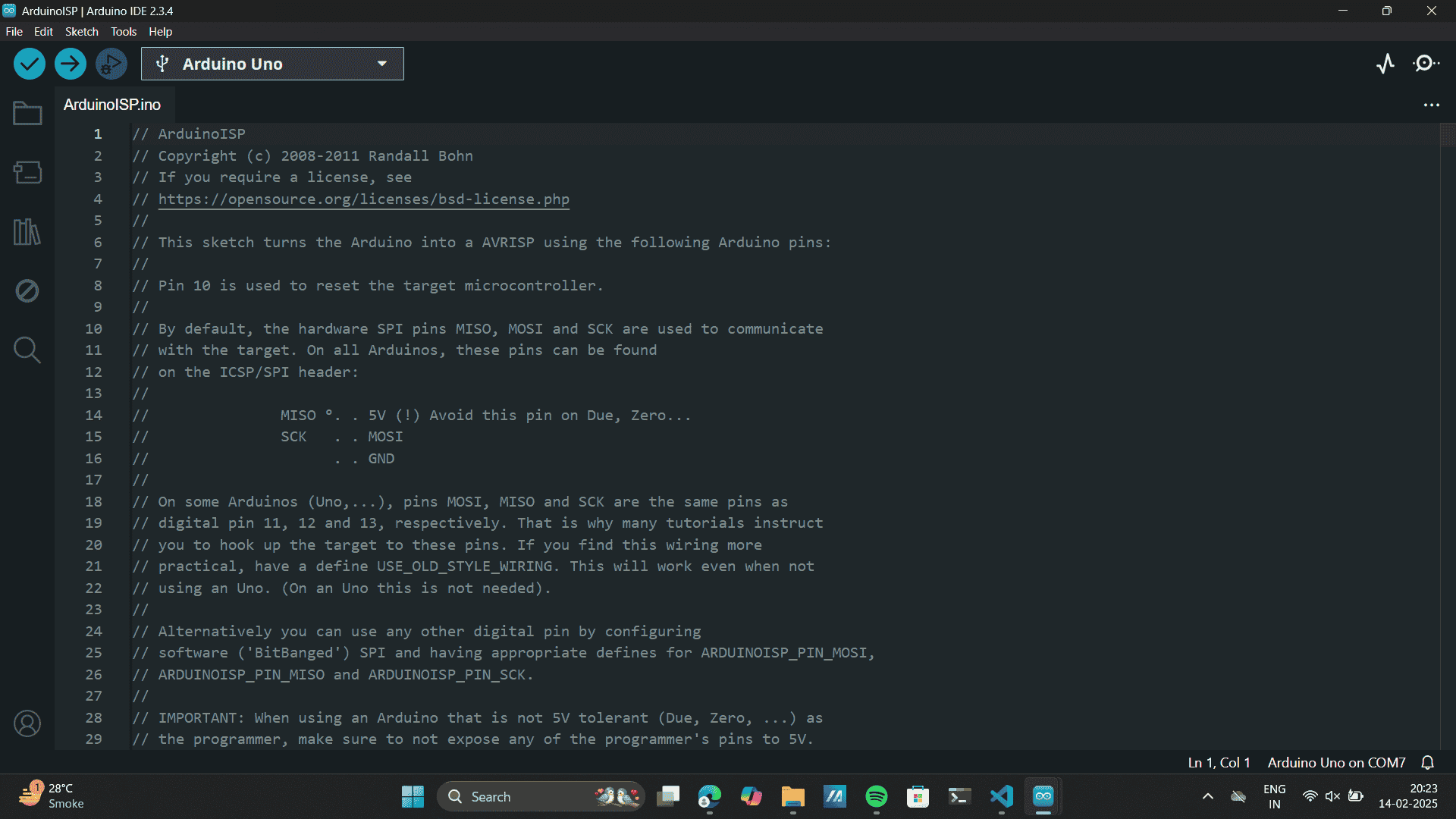
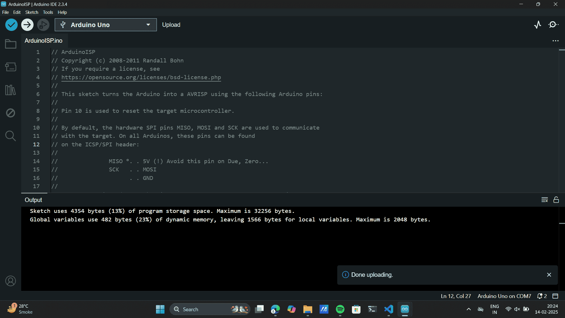
Connect your Arduino Uno to your computer and open Arduino IDE.
Go to File > Examples > 11. ArduinoISP > ArduinoISP and upload this code to the Arduino Uno.
This converts the Arduino into an ISP programmer.
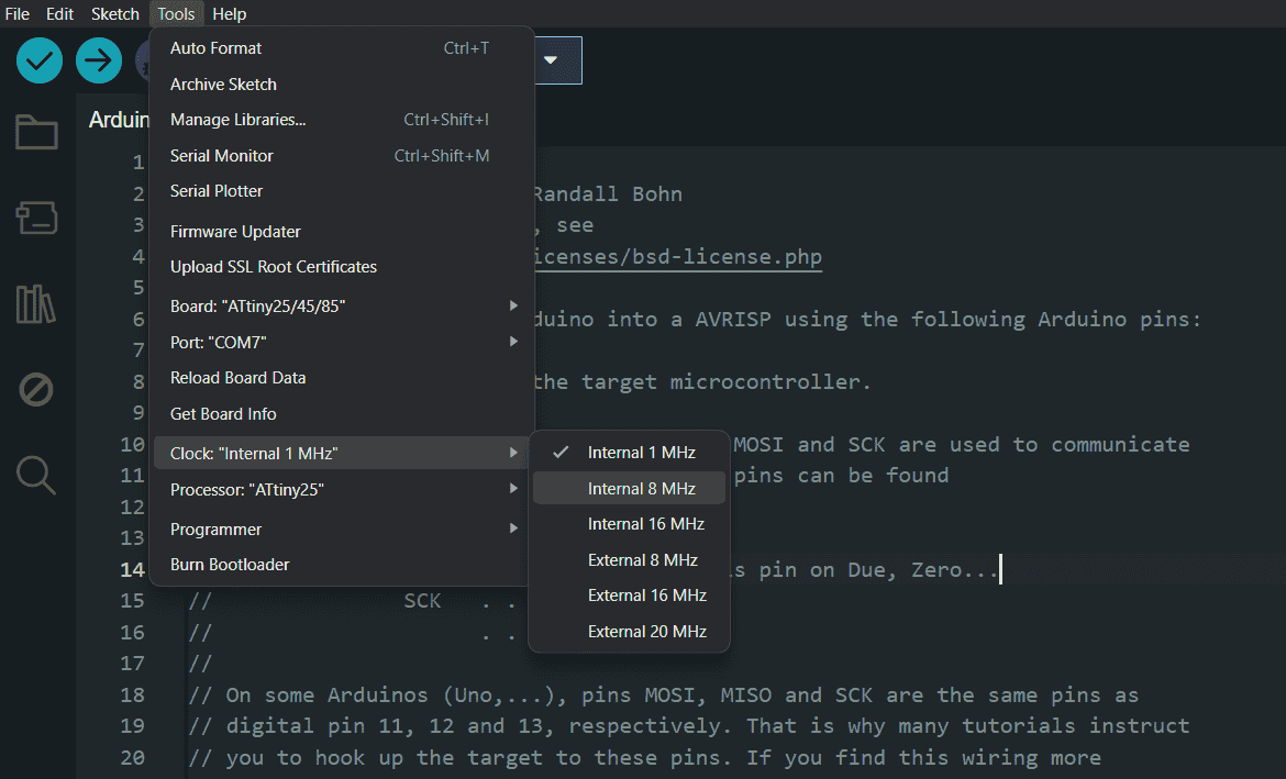
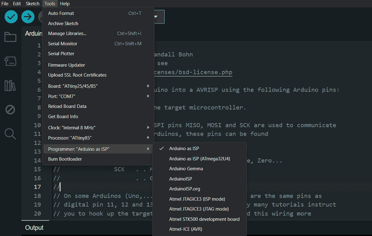
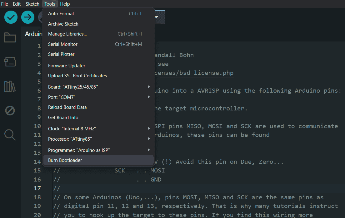
Burn Bootloader:
In Arduino IDE, go to Tools and set:
Board: ATtiny85
Processor: ATtiny85
Clock: 8 MHz (Internal)
Programmer: Arduino as ISP
Click Burn Bootloader to erase the memory and set the correct clock speed.
Step 4: Uploading Code to ATtiny85
Now, write or load the desired program (e.g., LED blinking, switch-controlled LED).
Change the board settings back to ATtiny85.
>Select Arduino as ISP as the programmer.
Click Upload to transfer the code to ATtiny85.
The
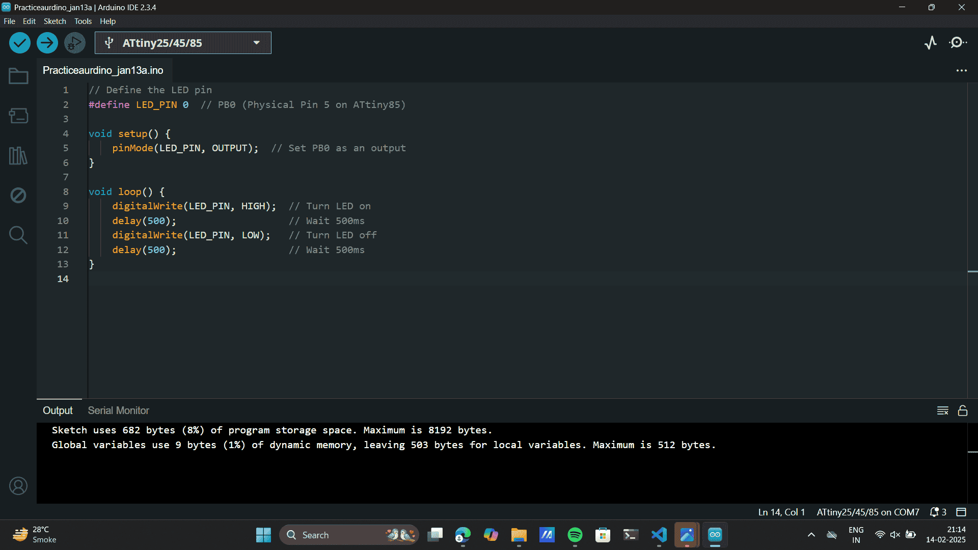
Chat GPT Prompt I used: Write an Arduino code for ATtiny85 to blink an LED connected to PB0 (Physical Pin 5). The LED should turn on for
500ms and off for 500ms repeatedly
This generated the code I wrote and used for an ATtiny85 microcontroller that makes an LED connected to PB0 blink on and off every
500 milliseconds is as mentioned below:
        /*
        // Define the LED pin
        #define LED_PIN 0  // PB0 (Physical Pin 5 on ATtiny85)

        void setup() {
            pinMode(LED_PIN, OUTPUT);  // Set PB0 as an output
        }

        void loop() {
            digitalWrite(LED_PIN, HIGH);  // Turn LED on
            delay(500);                   // Wait 500ms
            digitalWrite(LED_PIN, LOW);   // Turn LED off
            delay(500);                   // Wait 500ms
        }
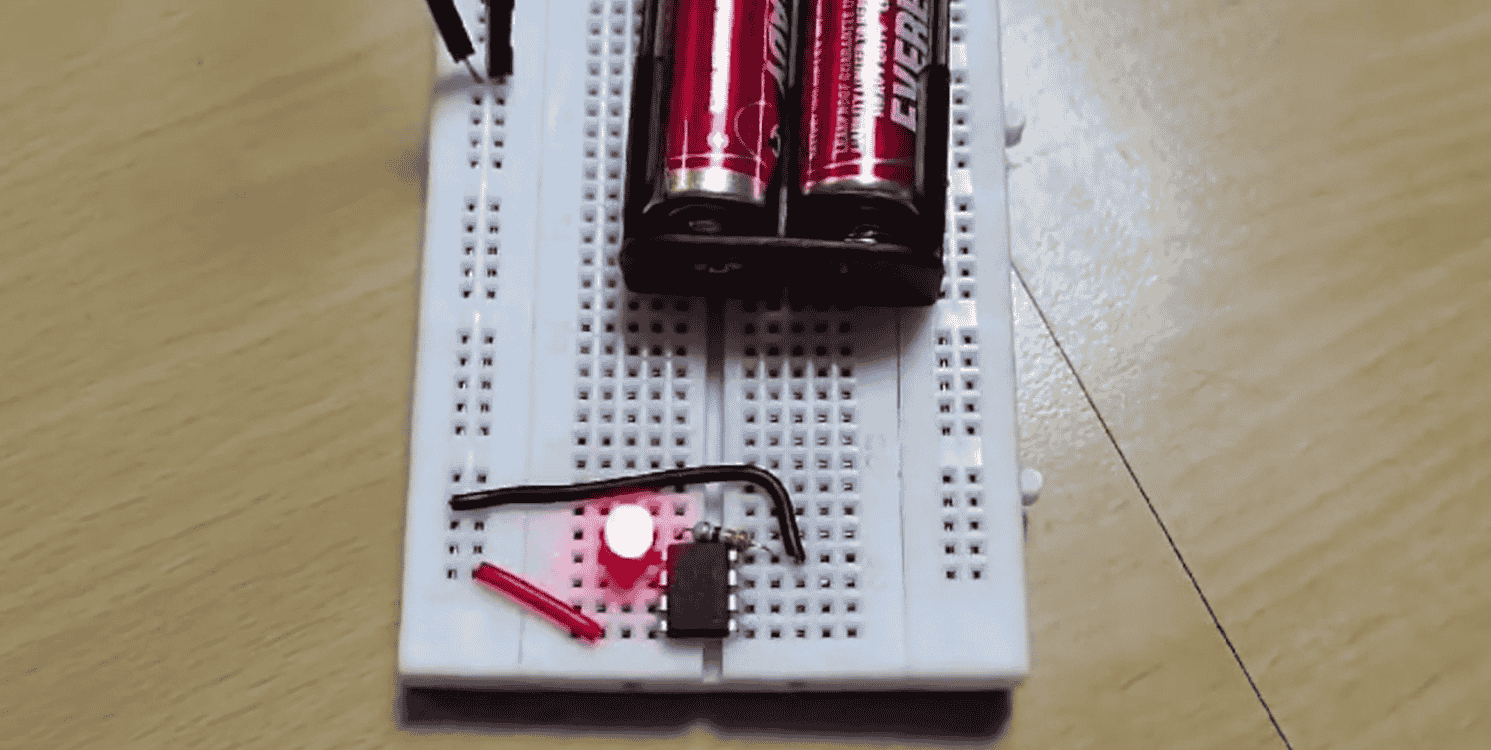
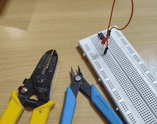
Step 5: Testing functionality
I build the LED circuit on a breadboard along with two essential tools: a wire stripper (yellow-handled)
and a flush cutter (blue-handled). This cleans the circuit for better fitting in circuits.
Final Circuit:
Notes for personal reference:
generate a code for blinking a led add a push button using attiny85 also give a schematic an dpin
confirmation
one shot push button...
at tiny need power connection, aurdino acts as isp: Insystem programmer
eerom : bootload, at. tiny board manager
Install attniy libraray, tools selctc, board, attiny 85(max clock speed, 8hz)
git hub link which we took from chat gpt: which allowed us to install borad manager for attiny 85.
aurdino programmmer:
select board as aurdino uno.
files: examples: 11.audino isp: isp
code
upload to aurdino,,
(we are converting aurdiono to isp)
microprocessor need 3.3 v
do the connections
then change board.
tools clock 8mhz
change processor.change progremmer as uardino isp
burn the boot loader. earse its memory
brain gaya
now add wowki code to aurdino and,,,,,,,,,, upload brain to that dabbba ie:atny
 Entering the Additional Boards Manager URL from the SEEED Studio documentation.
 Select the Correct Package:
Choose "Raspberry Pi Pico/RP2040/RP2350".
This package supports Raspberry Pi Pico, Pico W, Pico 2, and other RP2040-based boards.
Install the Package.
Select the Correct Package:
Choose "Raspberry Pi Pico/RP2040/RP2350".
This package supports Raspberry Pi Pico, Pico W, Pico 2, and other RP2040-based boards.
Install the Package.

.png)
 Soldering Components like LED, resistors and switch.
.png)
.png)
.png) The
Chat GPT Prompt I used: Write an Arduino code for ATtiny85 to blink an LED connected to PB0 (Physical Pin 5). The LED should turn on for
500ms and off for 500ms repeatedly
This generated the code I wrote and used for an ATtiny85 microcontroller that makes an LED connected to PB0 blink on and off every
500 milliseconds is as mentioned below:
The
Chat GPT Prompt I used: Write an Arduino code for ATtiny85 to blink an LED connected to PB0 (Physical Pin 5). The LED should turn on for
500ms and off for 500ms repeatedly
This generated the code I wrote and used for an ATtiny85 microcontroller that makes an LED connected to PB0 blink on and off every
500 milliseconds is as mentioned below:
 Final Circuit: