Assignment Brief:
- As a group assignment: Complete your lab's safety training.
- Test machine parameters: Runout, alignment, fixturing, speeds, feeds, materials, and toolpaths.
- Design a large (~meter-scale) object.
Mill the designed object using the tested machine settings.
Assemble the milled parts into a final product.
Computer-controlled cutting
A computer-controlled machine is a machine that operates using pre-programmed instructions from a
computer rather than manual control. These machines follow precise digital commands to perform tasks
like cutting, milling, engraving, 3D printing, or assembling.
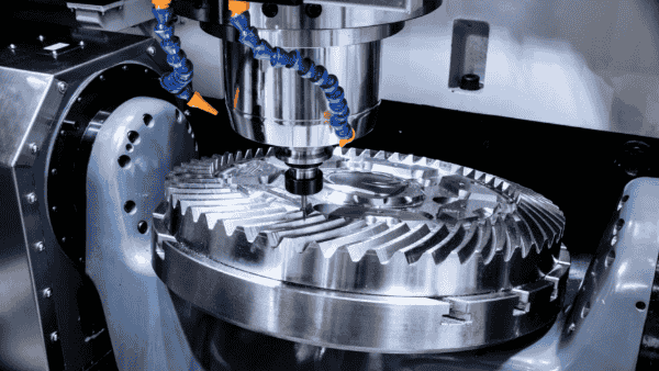
CNC (Computer Numerical Control) Machines
A CNC machine is an automated manufacturing tool controlled by a computer using numerical commands. It
eliminates the need for manual operation by following pre-programmed instructions, allowing for high
precision, repeatability, and efficiency in shaping various materials like metal, wood, plastic, and
composites.
Types of CNC Machines
- CNC Milling Machine: Uses rotating cutting tools to remove material, available in 3-axis,
4-axis,
and 5-axis models.
- CNC Lathe: Spins the material while a cutting tool removes excess material, ideal for
cylindrical
objects.

- CNC Router: Similar to a milling machine but mainly used for wood, plastics, and soft
metals. This is the CNC router
that we use in the Riidl Fab lab.
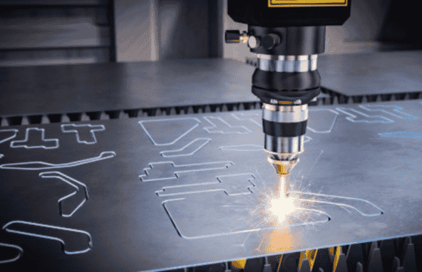
- CNC Laser Cutter: Uses a laser beam to cut or engrave materials like wood, acrylic, and
metal.
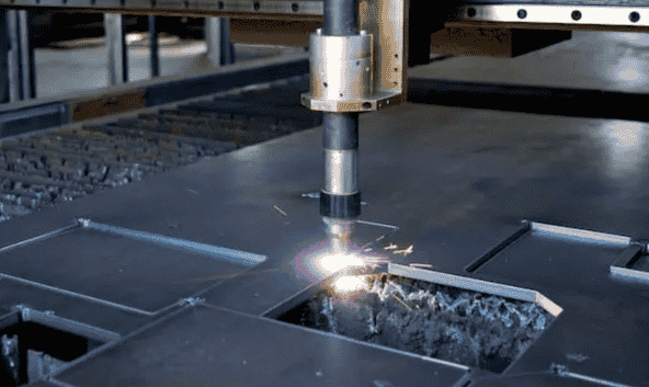
- CNC Plasma Cutter: Uses a plasma torch to cut electrically conductive materials.
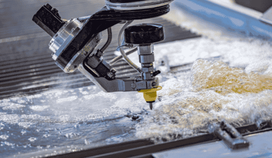
- CNC Waterjet Cutter: Uses high-pressure water with abrasives to cut through hard materials
like
stone and glass.
How CNC Machines Work
- CAD (Computer-Aided Design): The design is created in software like AutoCAD, Fusion 360, or
SolidWorks.
- CAM (Computer-Aided Manufacturing): The design is converted into G-code for machine execution.
- Machine Setup: The material is fixed, and tools are prepared.
- Execution: The machine follows the G-code to cut, drill, or shape the material.
- Finishing: The product is removed, inspected, and polished.
Advantages of CNC Machines
- High Precision: Ensures accuracy up to microns.
- Repeatability: Produces identical parts consistently.
- Efficiency: Faster production compared to manual machining.
- Flexibility: Can produce complex designs with multiple tools.
- Reduced Waste: Optimized cutting paths minimize material loss.
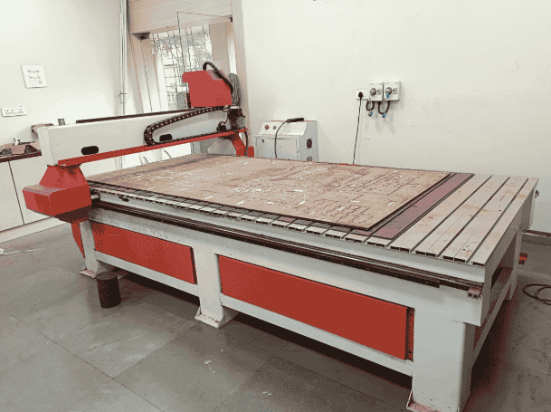
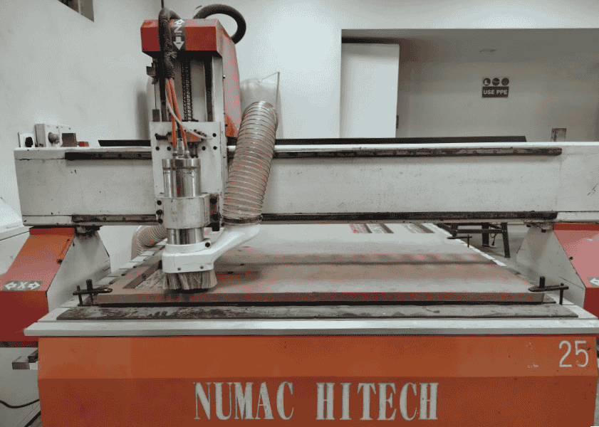
Riidl Fablab CNC Machine: Numac Hitech CNC machine
The Numac Hitech CNC machine is a high-precision, large-format CNC router designed for cutting,
engraving, and milling various materials. Given its 8' x 4' (2400 mm x 1200 mm) bed size, it is ideal
for working with full-size sheets commonly used in fabrication and industrial design.
Key Features
- Large Work Area: Supports full-size 8' x 4' sheets, making it ideal for furniture-making and
industrial projects.
- High-Precision Cutting & Milling: Supports 2D and 3D cutting with accurate toolpath execution.
- Optimized for Large-Scale Production: Batch processing and material optimization reduce wastage.
Group work: Part 1
Safety instructions for using the CNC router:
- Wear PPE: Use safety goggles, ear protection, and a dust mask.
- Check the Work Area: Ensure the machine bed is clean and free of obstructions.
- Secure Material: Properly clamp the workpiece to prevent movement.
- Inspect the Machine: Check tool tightness, spindle alignment, and emergency stop function.
- Set Correct Parameters: Use appropriate feeds, speeds, and depth for the material.
- Stay Clear: Keep hands and loose clothing away from moving parts.
- Monitor Operations: Never leave the machine unattended while running.
- Use Proper Ventilation: Ensure adequate airflow to remove dust and fumes.
- Emergency Preparedness: Know the location of the emergency stop and fire extinguisher.
- Power Down After Use: Turn off the CNC machine and clean the work area.
Testing machine parameters: Runout, alignment, fixturing, speeds, feeds, materials, and toolpaths.
Recent Projects:
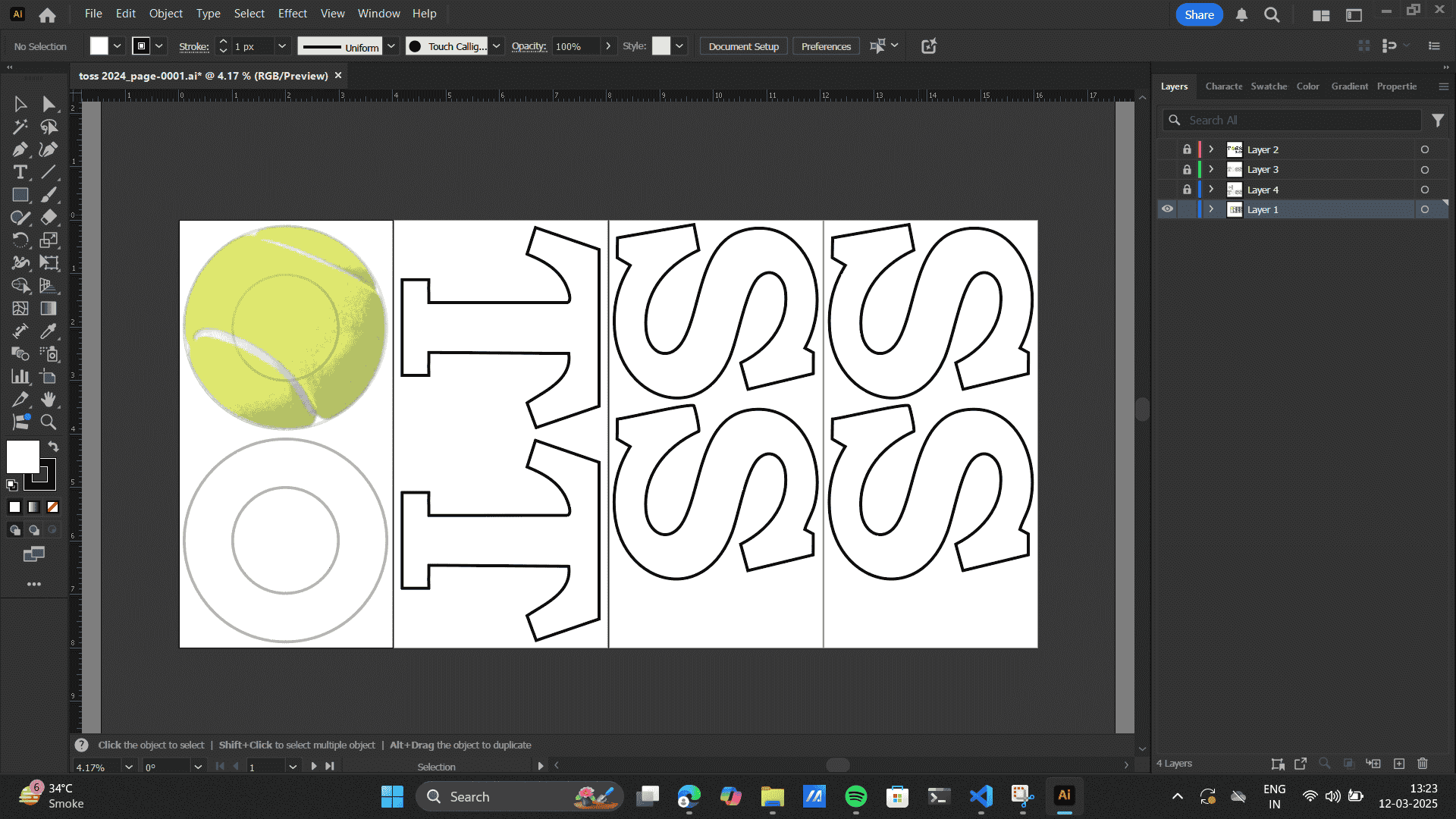
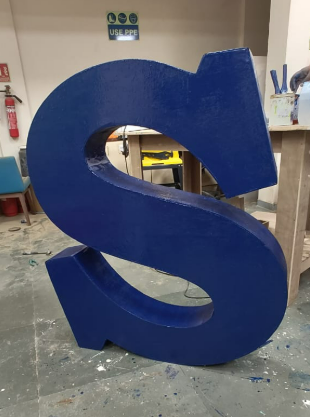
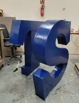
Fabricating 3D letters: TOSS
I, along with the help of my friends Sharvari Akerkar and
Kanika Kadam.
have recently built, designed and fabricating large 3D letters for TOSS, the annual sports event at
Somaiya Vidyavihar
University. Learn more about TOSS at the attatched link
here.
The event took place recently, and the goal was to create a bold and striking installation that
serves as a visual centerpiece on the grounds of Somaiya Cricket Ground, Sion.
Find the complete documentation video at @abstract_s16.
Process: Design and Fabrication of 3D Letters, TOSS
1. Conceptualization & Design Development
The process began with designing the letters, ensuring they were visually impactful and aligned with the
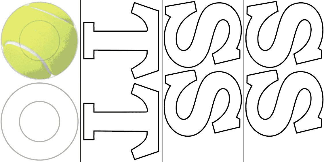
official TOSS event branding. The TOSS logo is as below
- Logo Tracing in Adobe Illustrator: The first step involved tracing the official
TOSS logo in Adobe Illustrator. This process required precision to ensure that the curves and
typography matched the original branding. The traced version was then converted into scalable vector
outlines, allowing for high-resolution resizing without distortion.
- Exporting to Fusion 360 for CNC Manufacturing: Once the tracing was complete, the
vector file was imported into Fusion 360 in DXF format. Here, exact dimensions were defined for each
letter,
ensuring proper proportions and alignment. Fusion 360 allowed for precise parameter-based modeling,
which was crucial for ensuring that the design translated seamlessly into the CNC manufacturing
process.
- CNC Machining Setup
The Numac Hitech CNC router (8' x 4' bed) is calibrated for precision.
Key machine parameters set include:
Toolpaths: Contour cuts for letters
Fixturing: Clamping the plywood securely
Speeds & Feeds: Adjusting spindle speed and feed rate for optimal cutting
A test cut is performed on scrap material to confirm alignment and depth settings.
Cutting & Fabrication:
The CNC machine mills out the letters while ensuring smooth edges.
Post-cut, the edges are hand-finished using sanding tools to remove rough fibers.
Structural reinforcements are added for stability if required, ensuring the letters stand upright
when placed outdoors.
- Assembly & Installation:
The finished letters are assembled on-site at Somaiya Cricket Ground.
If necessary, a base support system is added to withstand outdoor conditions like wind.
The final installation serves as a visual centerpiece for the TOSS event, making a bold and striking
statement.
My learnings
1. Challenges in Working with Flexible Ply
Working with flexible plywood introduced unique challenges that needed to be addressed throughout the
fabrication process.
Understanding Material Properties: Flexible plywood bends easily due to its thin
veneers and specialized grain orientation. However, improper handling could lead to cracking or
warping. It was essential to understand the material’s bending radius and apply gradual pressure
during forming.
2. Design for Manufacturing (DFM) & Material Optimization
Designing with manufacturing constraints in mind was a crucial step to ensure efficiency and
sustainability in production.
Optimizing Letter Sizes: One of the key considerations was optimizing the size of
each letter to fit within a single standard plywood sheet measuring 8' x 4' (2400 mm x 1200 mm).
This approach significantly reduced material wastage, minimized cost, and simplified the assembly
process. Layout nesting techniques were used in Fusion 360 to arrange the letters efficiently on the
sheet.
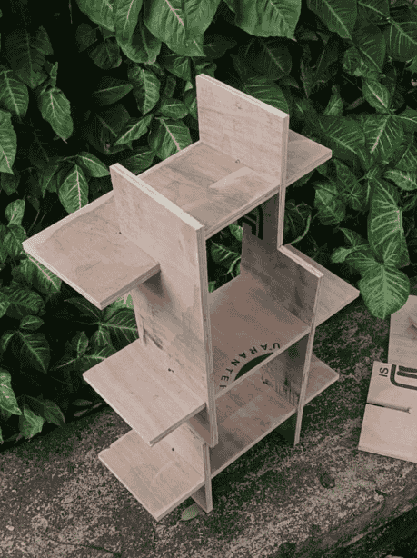
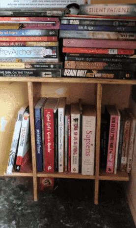
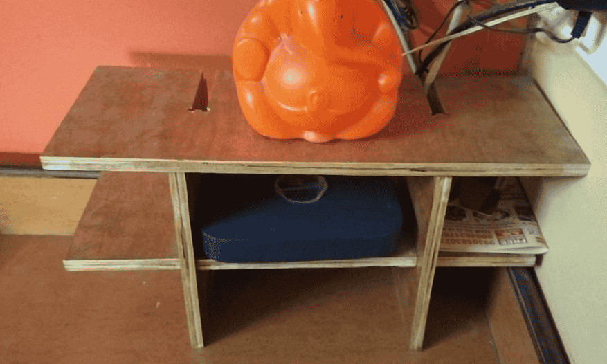
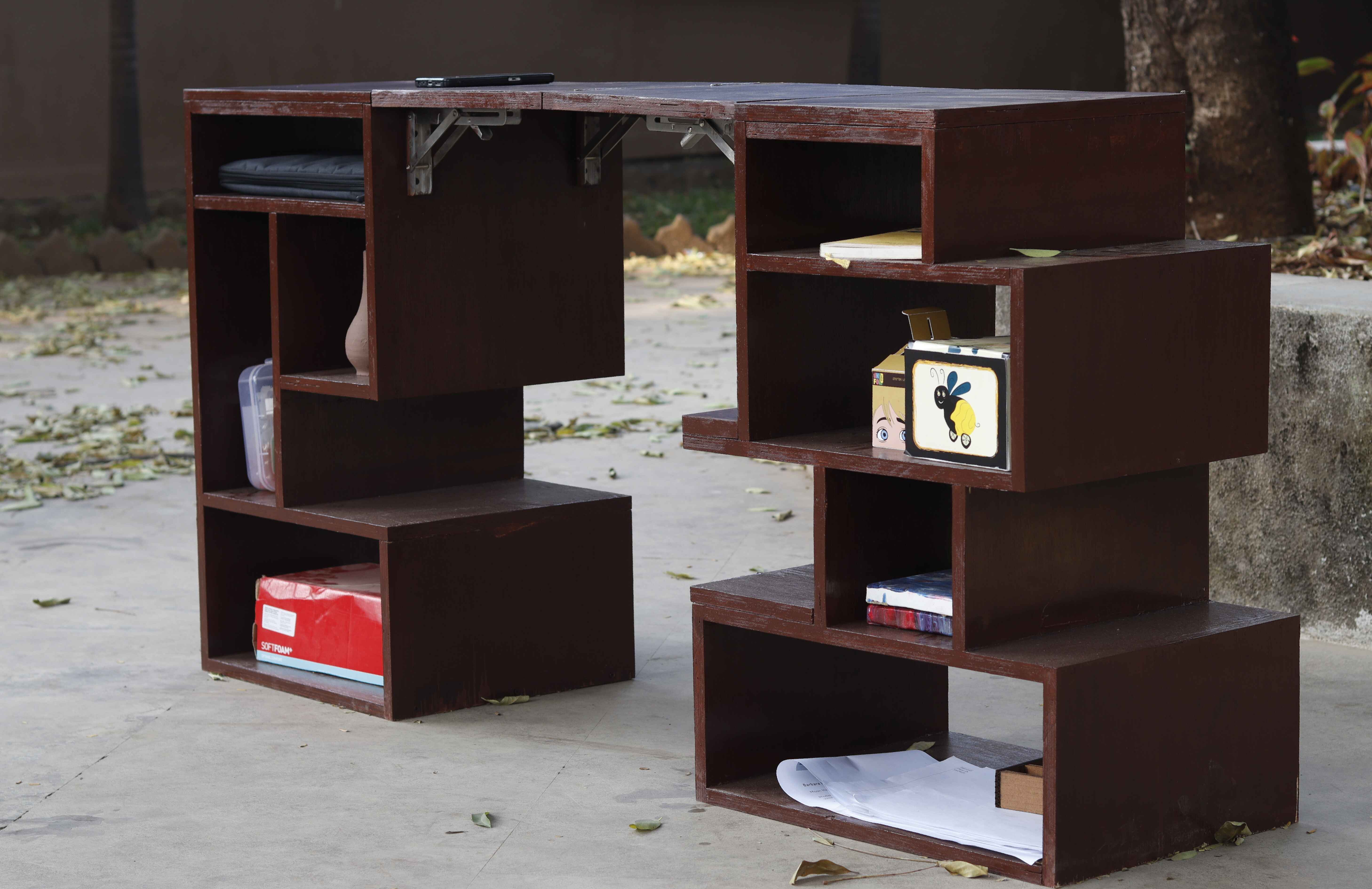
Parametric Book shelf
1. Conceptualization & Design Development
Renders
Cutting & Fabrication:
Milling 1:
Milling 2:
Sanding:
Assembly & Installation:
Final Outcome:
User Testing: Application at my home
My learnings
1. Slot Fit & Tolerance Adjustments
Precise slot dimensions are crucial. If the slots are too loose, the structure may wobble or collapse. If too
tight, assembly becomes difficult and may require force, potentially damaging the material. While i build
this structure
I realized that my slot joinery was a loose fit, which made the structure stand on straight as well as
slanted angles. The slanted angular structure was very firm, but it's base wasn't to the ground. On the
other hand,
If I placed the structure on with straight lines, it was parellel to the base but the stability was a little
low. Thought the model
was functional, I realised that a kerf test was required before building the model.
3. Interlocking Strength & Stability
The interlocking nature of the slots provides structural integrity without requiring screws or adhesives.
Slot positioning and orientation affect weight distribution. A crisscross or staggered slot pattern
increases balance and load-bearing capacity.
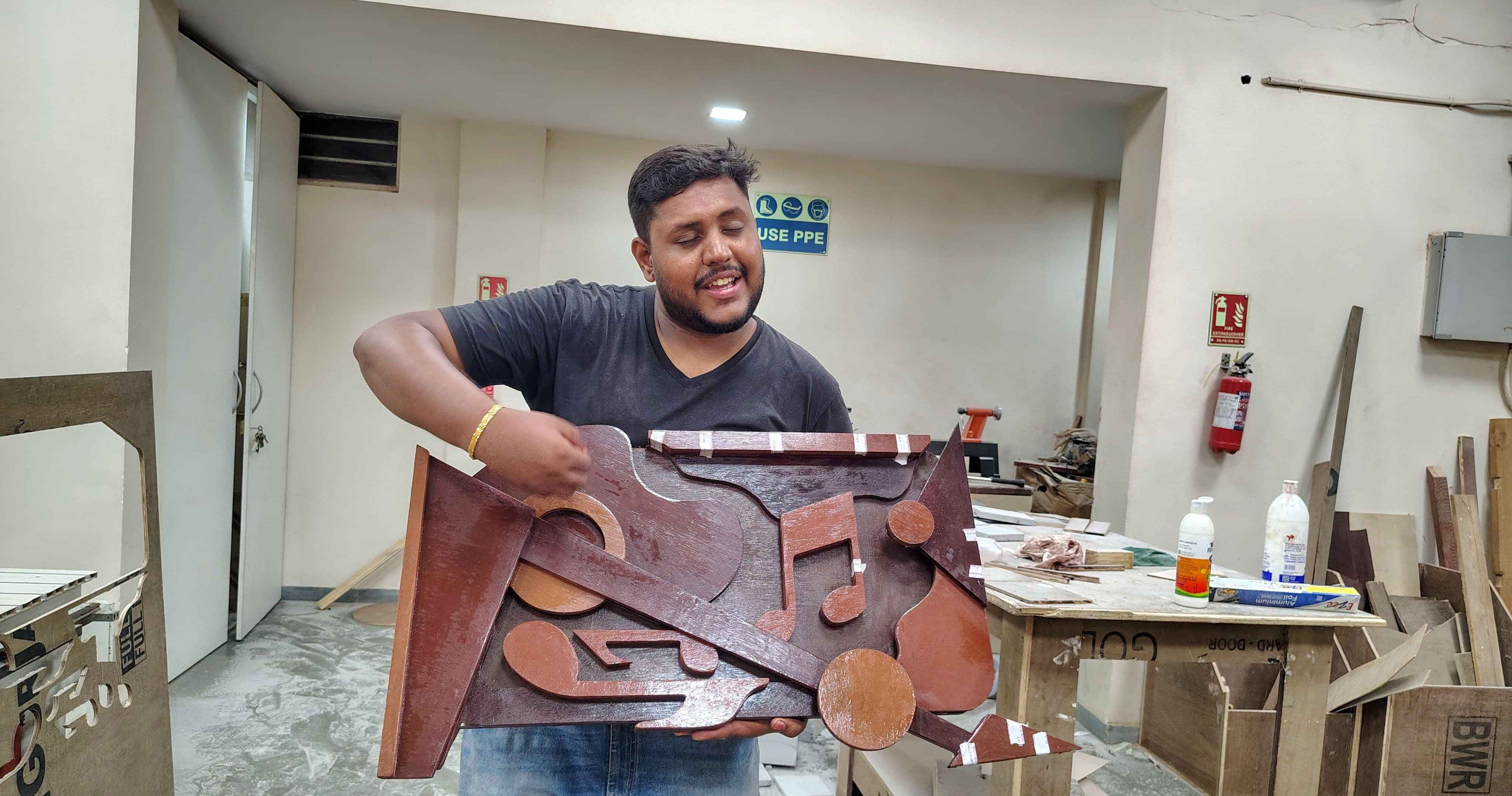
My assignment
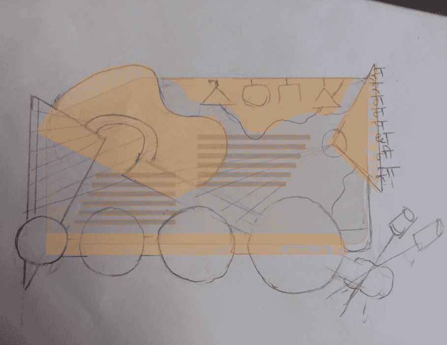
Layered art wall mount musical device.
A previous work on CNC had made me well acquainted with the processes and outcomes the machine could give.
Thus, for this week I thought of building someething out of the box. I was suggested to go with something
with ease of production, but that would limit my limit of reach. Further, I explored the intesity and
exception of production
of the CNC machine.
So I recalled that I aspired to build a wall mount interactive structure.
This was my initial idea for final project of making an interactive wall mounted frame.
Find the description about it in my final project documentation
here.
I thought ways of interactivity, to which a musical emitting caught my mind.
Using Human powered mechanisms, I thought of a
design idea for a musical wall mount that serves as both a functional interactive unit and a decorative
piece
Chat gpt prompt: Interactive wall mount
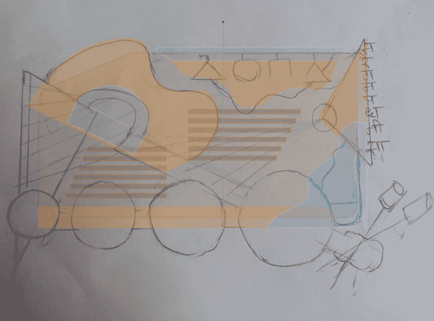
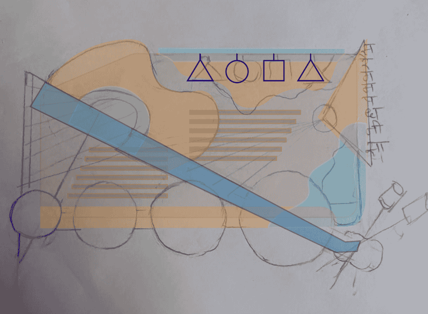
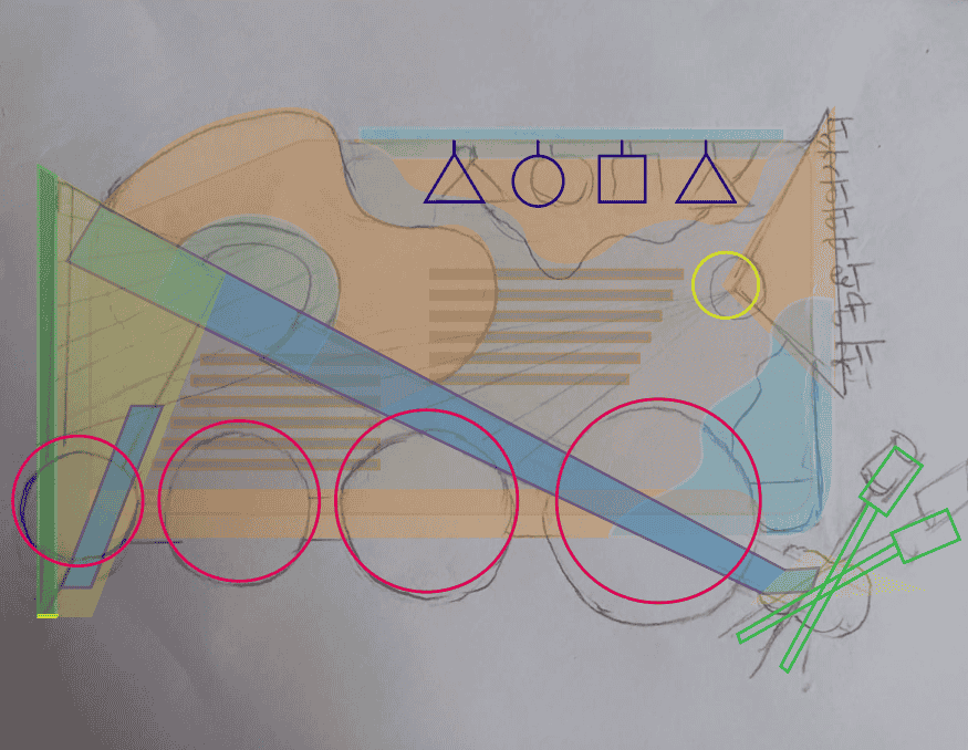
Sketching the design Idea.
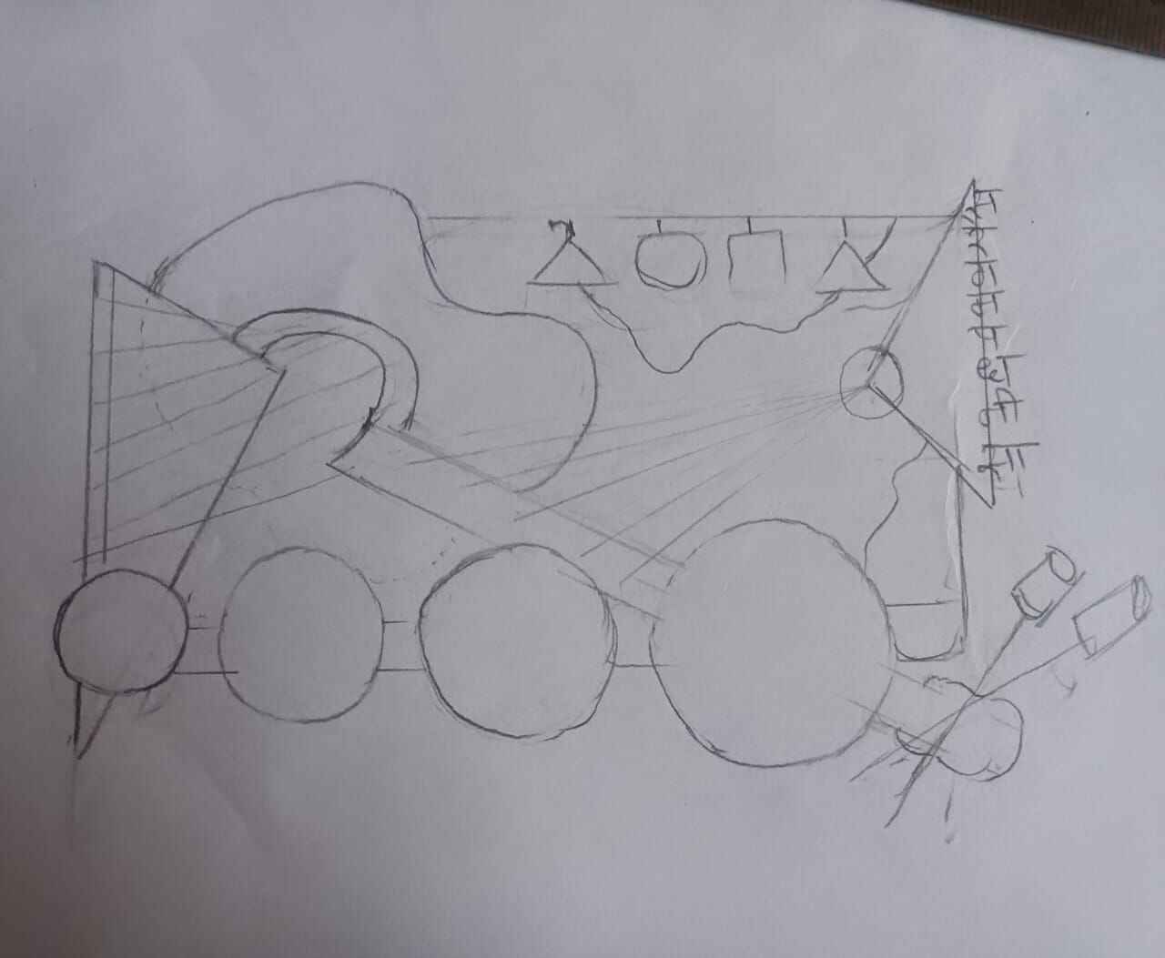
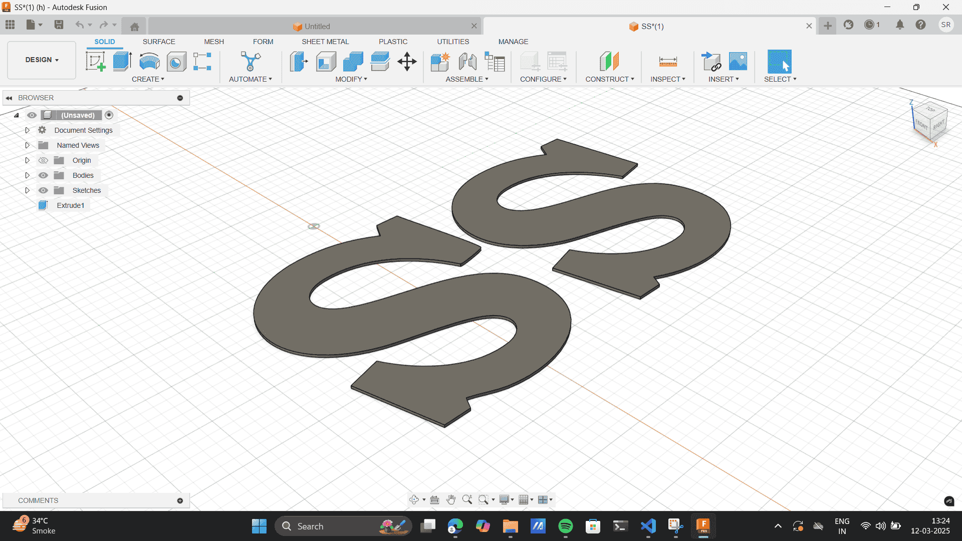
1. Conceptualization & Design Development
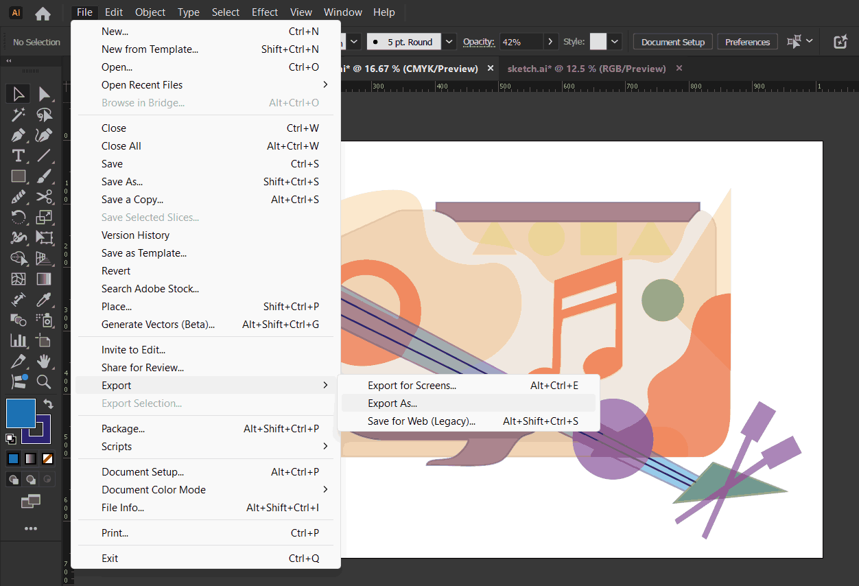
One the sketch was ready, I Imported the image on Illustrator and
traced each of the elements as different layers.
Import the image file on Illustrator: Open image> Copy> paste.
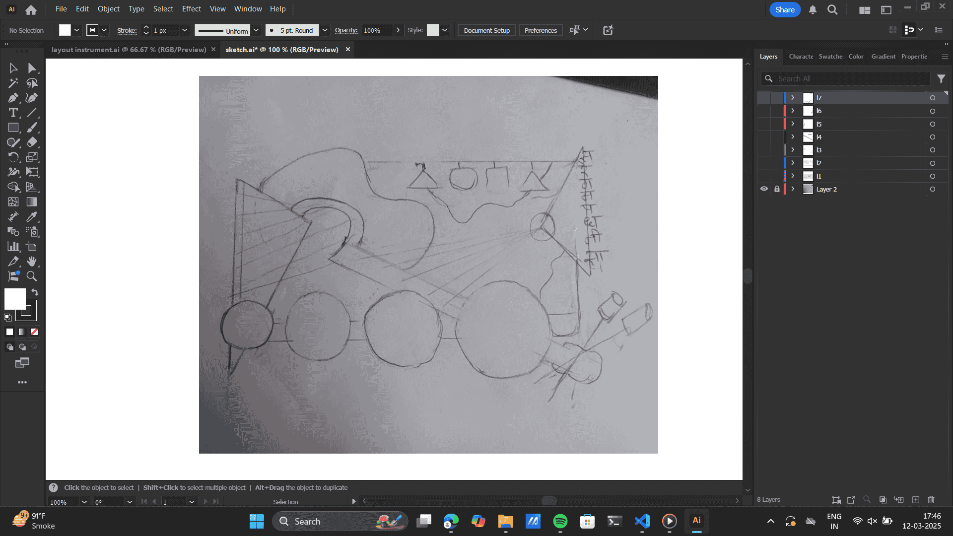
Make a new layer> Curvature tool> trace the bottom layer>
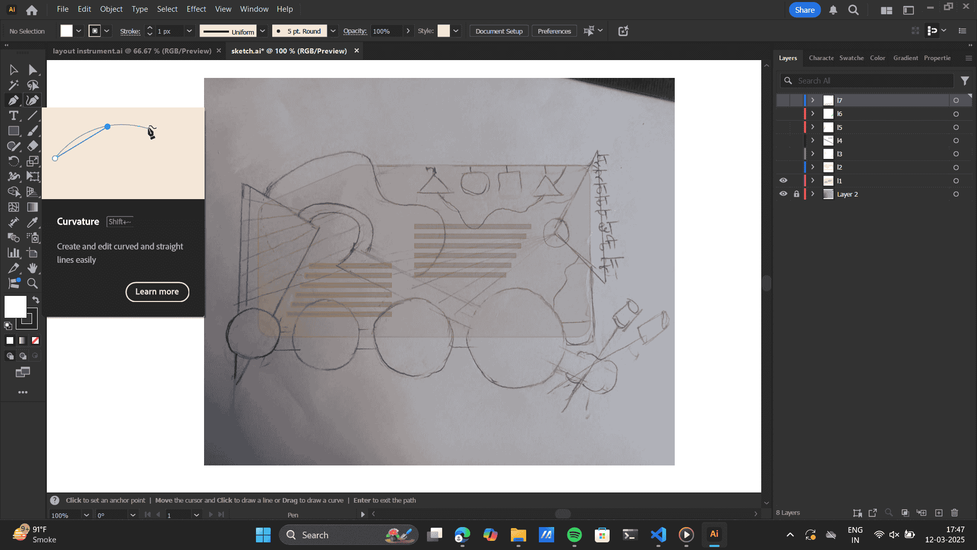
Layer by layer segregation of each layer as would be on the model.
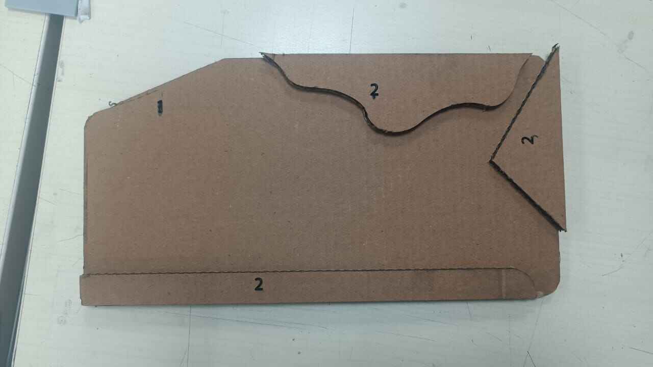
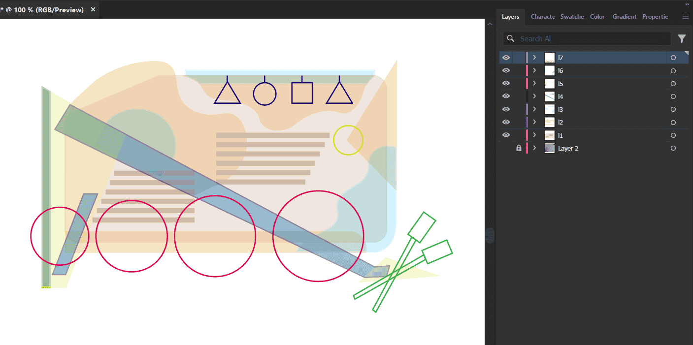 New Illustrator file> Layout of each file as new layer.
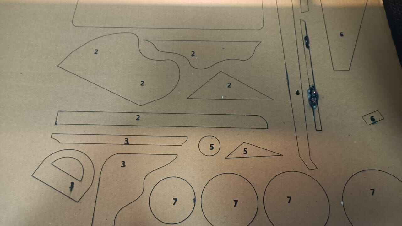
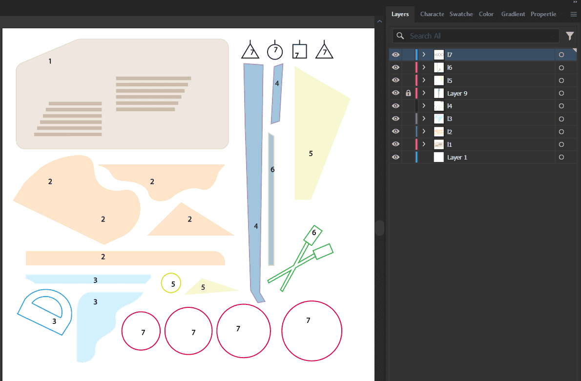 Further, I laser cut this file.
 As you see, one of the piece in the laser cut is burnt.
this was due to the bed leveling. I set the bed level ande got that specific piece laser cut.
To know more about laser cutting, Refer to my Week 3 documentation
Computer Controller cutting
 Assembly
Final Prototype
Assembly
Final Prototype
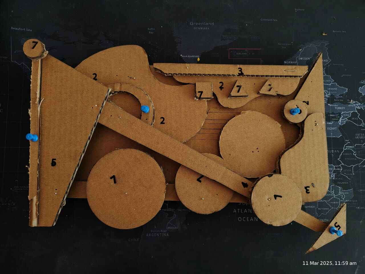
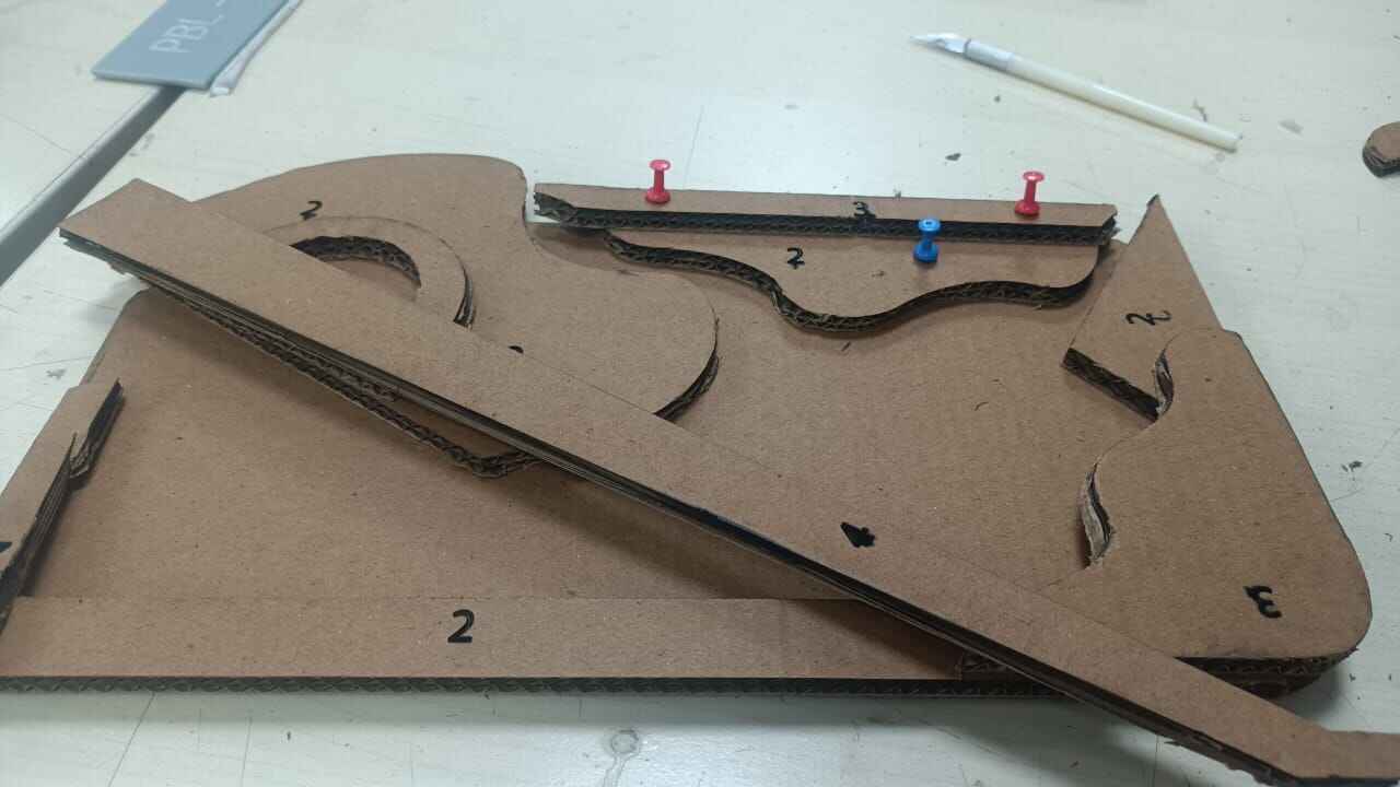
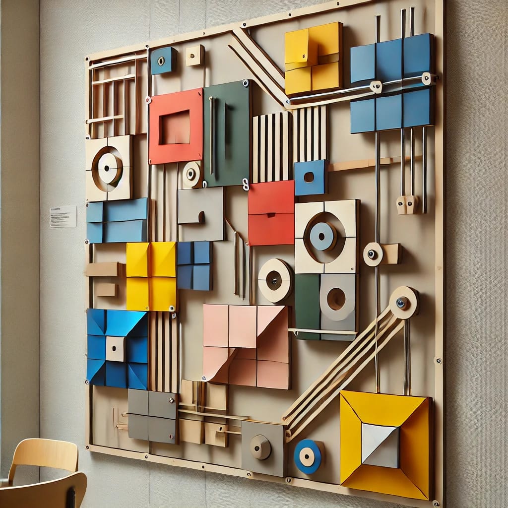
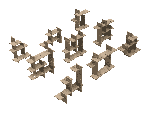
This is the prototype of my musical wall mount, created using layered cardboard to represent different
structural elements. The blue pins indicate anchor points for strings, which will be stretched between them.
Once attached, these strings can be plucked or strummed, producing sound, making the design not just a
visual installation but also an interactive musical piece. This prototype helps visualize form, function,
and material connections before developing the final version. The attatchment between each of the
models will be with dowels.
Designing: Fusion 360 for CNC
The next aim was to translate this design fusion 360, reason being 1)To set-up the CNC manifacturing set up
and 2)Adding dowels
to the overall structure as a fastner.
Colour coded every part and built to Separate layers on Illustrator.

Exported the whole file as DXF set the scale dimesions as of the file.
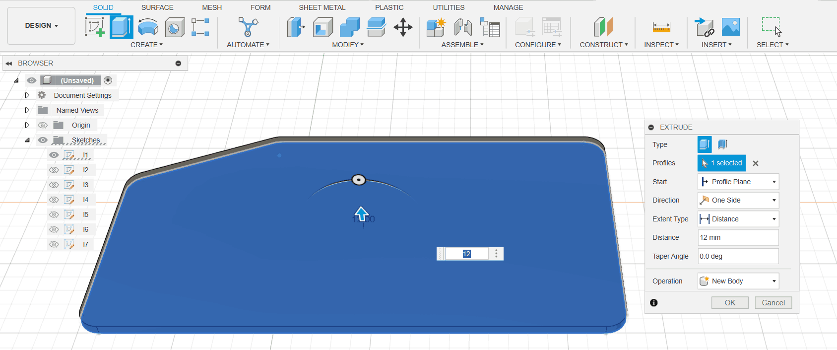
Learning: I Set-up the overall dimension width as 1m. Previously, I took the dimension to be of 2 meters,
However when I gave a thickness to the material of 12mm the
the aesthetic of it was lost.I realised that on the corrogated scaled model the material thickness added up
to make the piece look
like a layered art. Thus the material thickness would be proportional and will determine the the overall
aesthetic and form of my model.
This made me switch to a dimensional width of 1 meter.
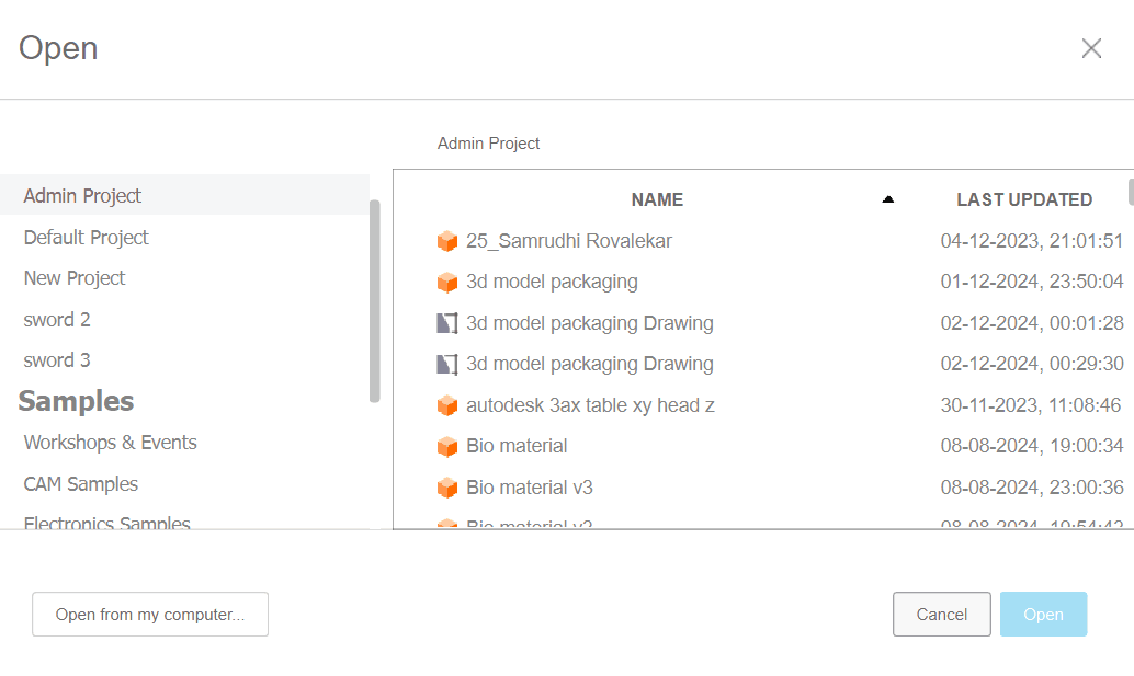
To import the DXF file, File> Open
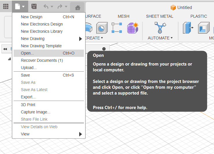
Open from computer> Browse your file location and import.
Select the plane you want to import the file. I selected the top plane.
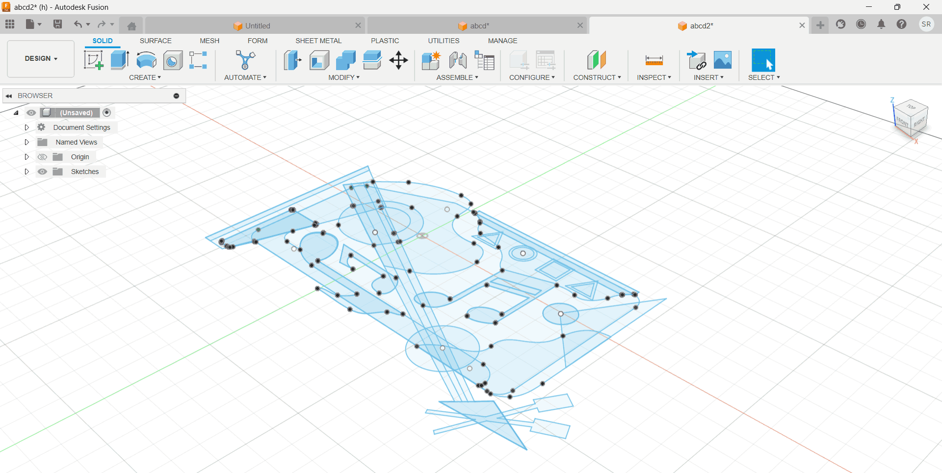
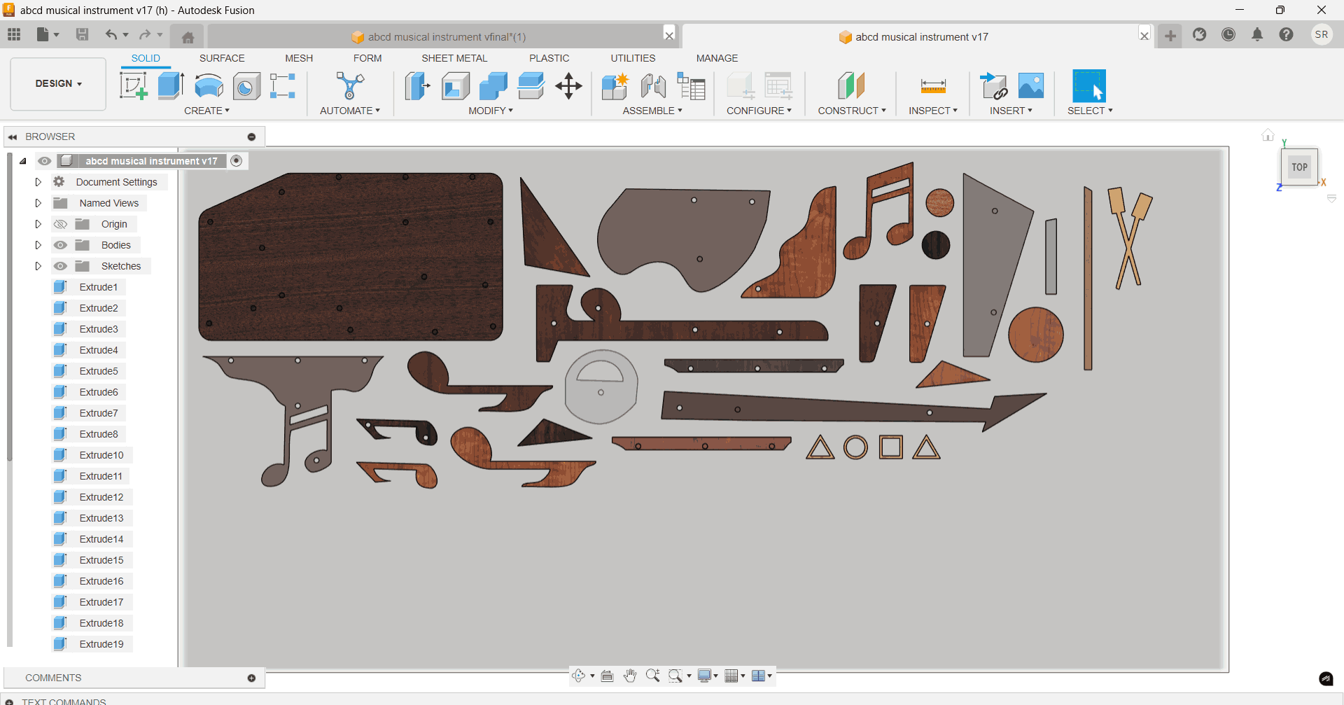
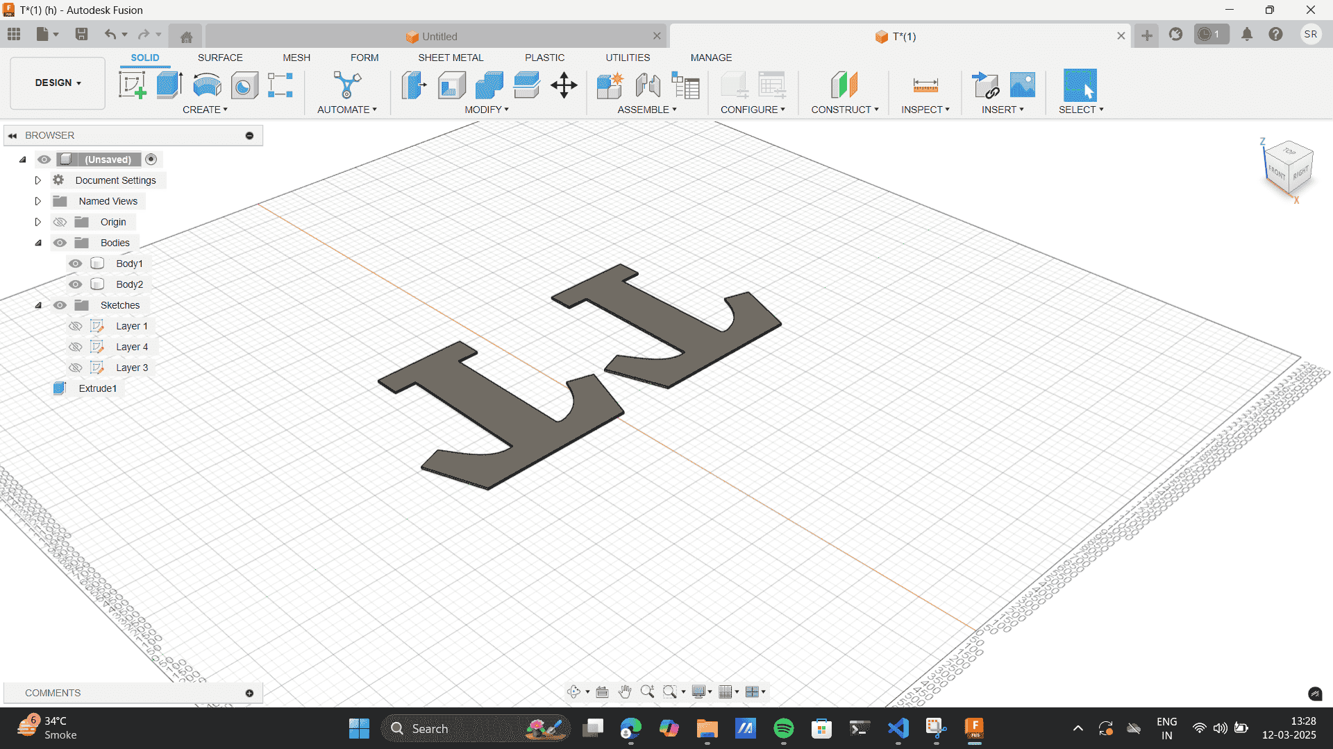
As you open the sketches panel, each layer of the model was on a different sketch layer.
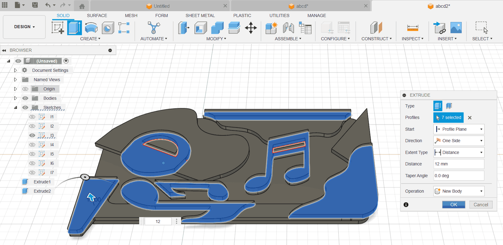
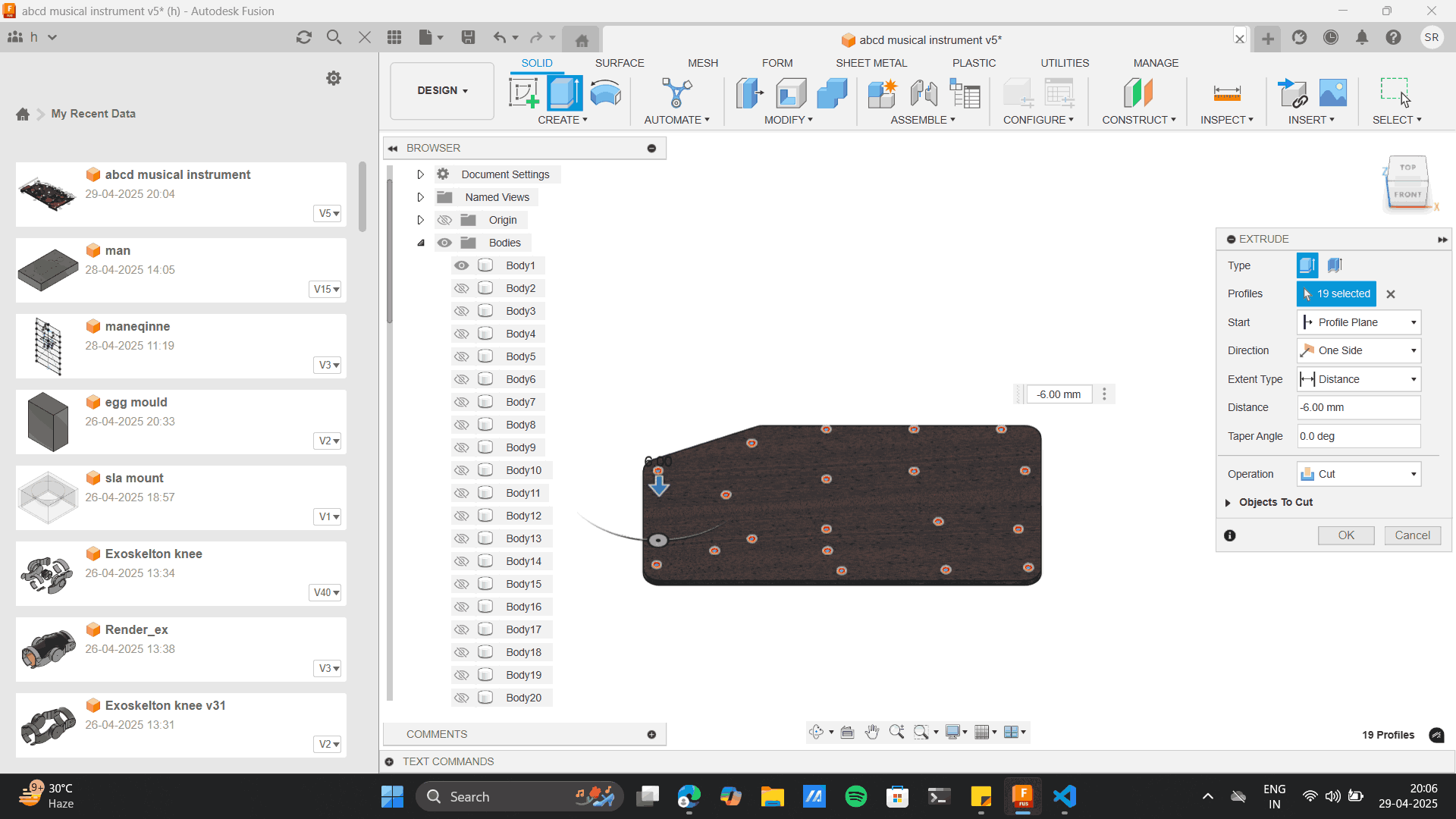
I turned off all layers excpet base and extruded it to my material thickness of 12mm.
Note to
Extrude as new body every time, you extrude.
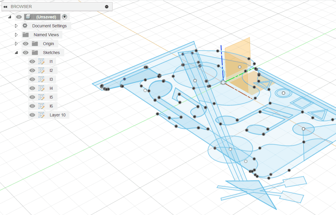
Turned on other layer> Moved them 12mm up and then only extruded layer 2.
Similarly, Except layer 1 and 2 I moved all layers up by 12 mm.
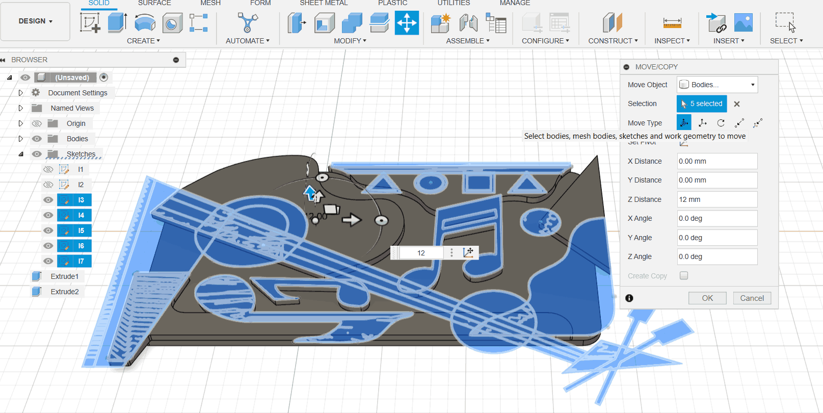
Extrude layer 3 while switching of all other layers.
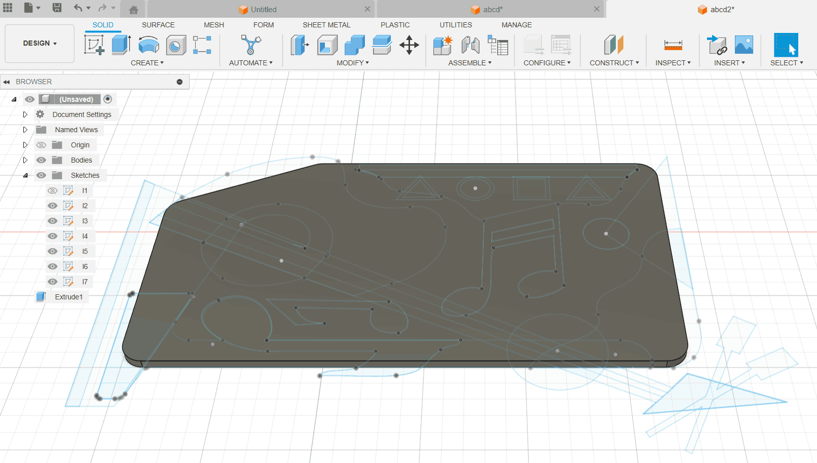
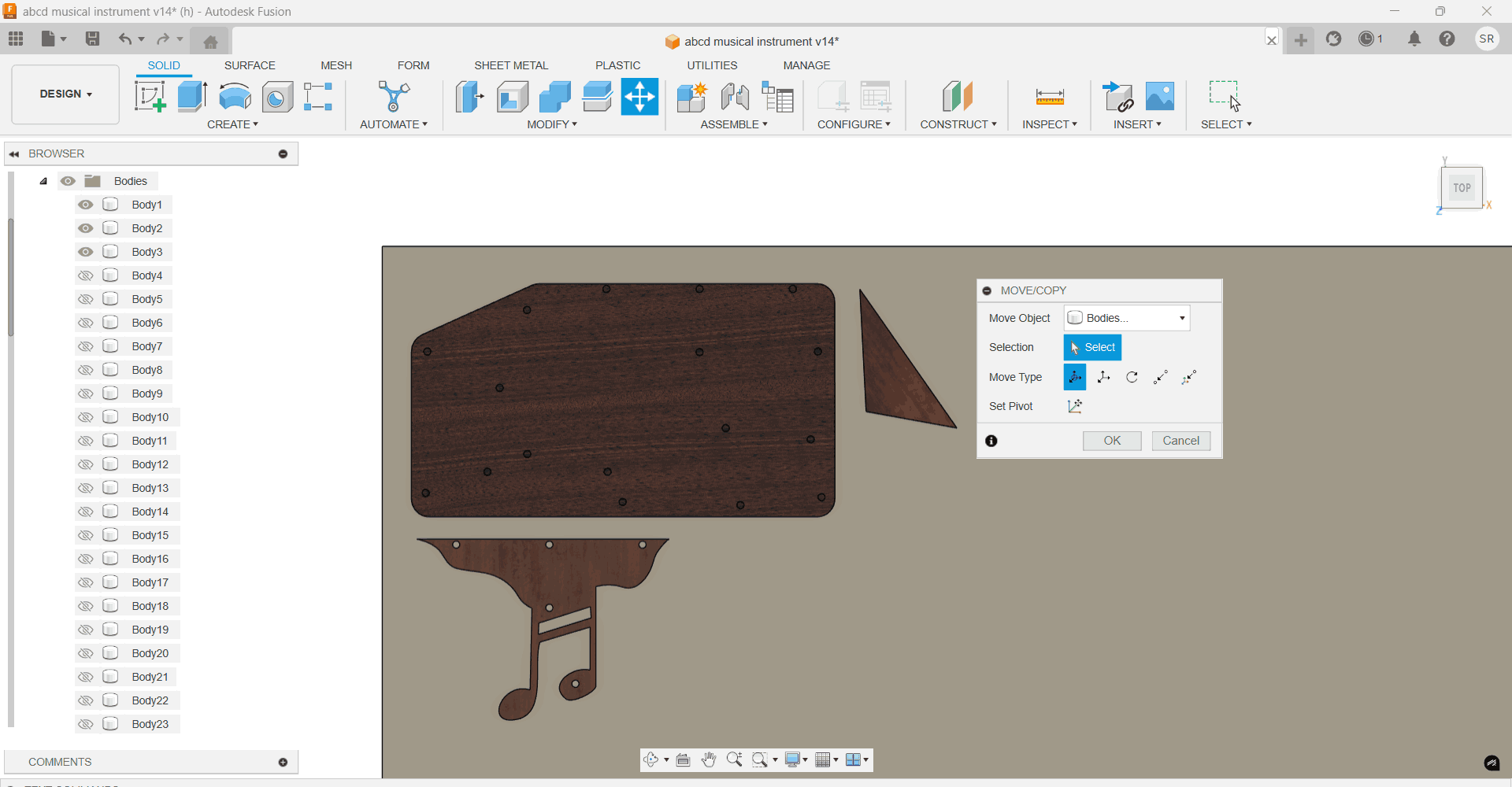
I used the Move Tool to shift each consecutive layer individually. Starting from the base layer, I extruded one
layer at a time by temporarily hiding or closing off the visibility of the other layers. This step-by-step
extrusion approach allowed me to control the form and ensure precision at each stage of the build.
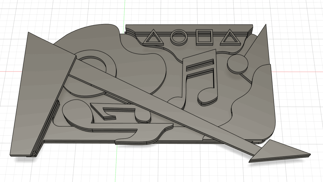
Final Model
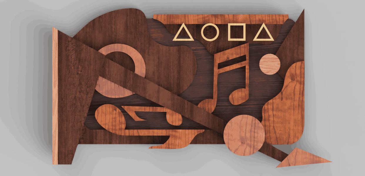
Render
Dowels: Fastner and stuctural support
To bind one layer to the other, I thought of using a dowel. This would help my model if not fully but
1)Partial
fastner, 2) Structural support to the whole model and 3) Binding ease, Dowels positioning will help me
analyse the
proper position of each piece of my model during assembly. However, before going about adding dowels I
needed to learn about the
tolerances that our CNC machine would give us. Thus, I went about doing the Group assignment. This will help
me understand
tolerances, speeds fixures while cutting the main model as well.
Group Assignment: Part 2
The group assignment was to test runout, alignment, fixturing, speeds, feeds, materials,
and toolpaths for our machine.
Firstly, understandood each of the terminologies
- Test Runout: Measures how much a tool or part wobbles during rotation, ensuring accuracy.
- Alignment: Ensuring the tool, workpiece, and machine are correctly positioned to prevent errors.
- Fixturing: The setup or device that holds the workpiece securely during machining.
- Speeds: The rate at which the tool or workpiece moves, usually measured in RPM (revolutions per minute).
- Feeds: The rate at which the tool advances along the workpiece, typically in inches or millimeters per
minute.
- Materials: The substances being machined, like metal, plastic, etc.
- Toolpaths: The planned path the cutting tool takes to shape the material, determined by the program.
- Tolerance: The permissible variation in dimensions or other characteristics, ensuring parts fit together
properly without being too tight or too loose.
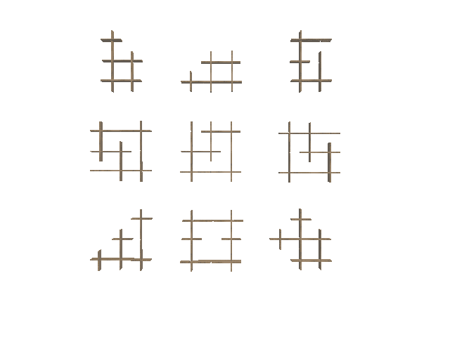
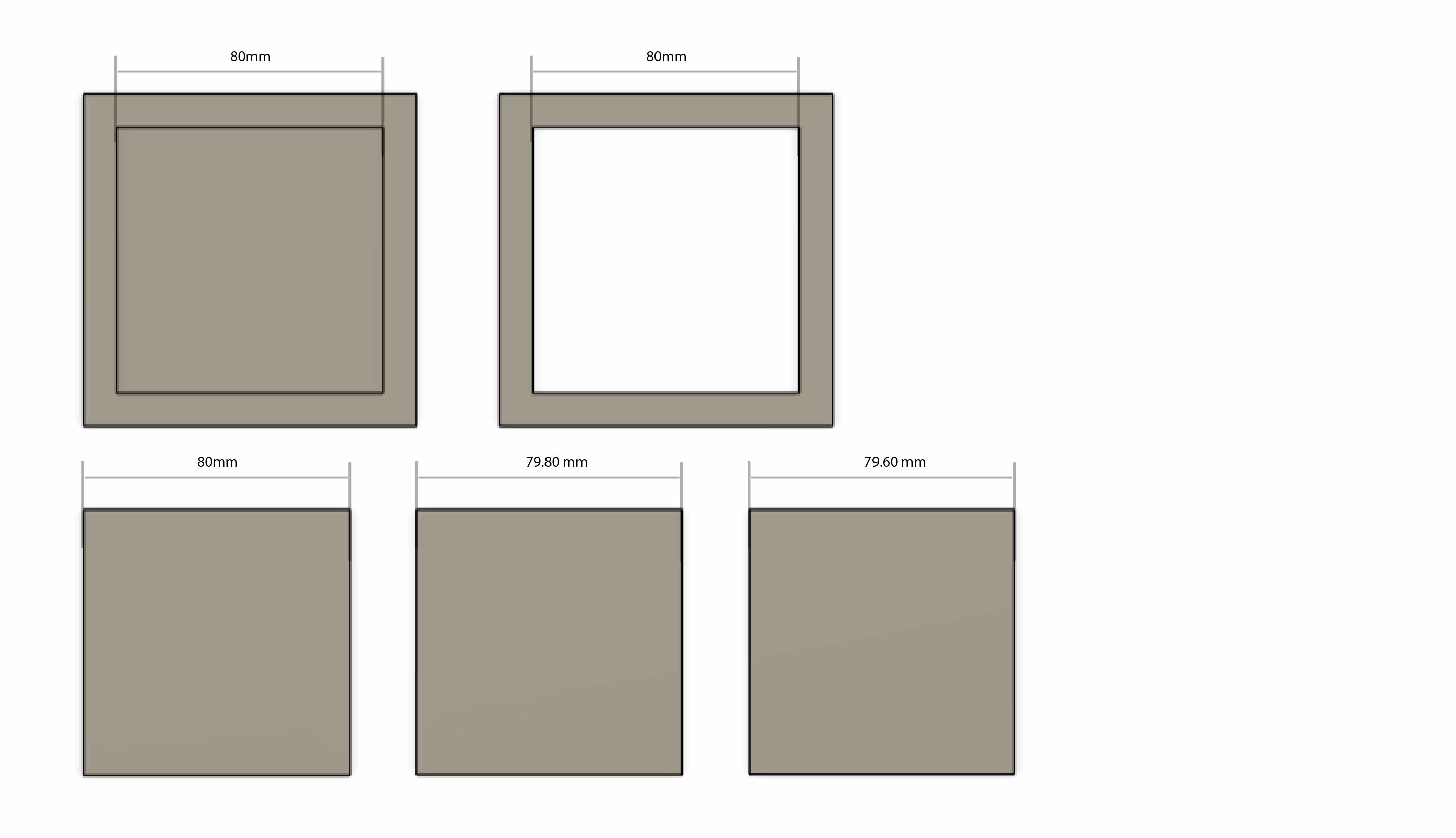
As checking the tolerance was my main purpose, I drew two squares with an outer dimension of 80 mm in a
pocket square and a through-hole square. I varied the length of the inner squares that will fit in the outer
squares
as follows: 80 mm, 79 mm, 80 mm,
and 79.60 mm. I made two extra tolerance but I didnt cut them later.
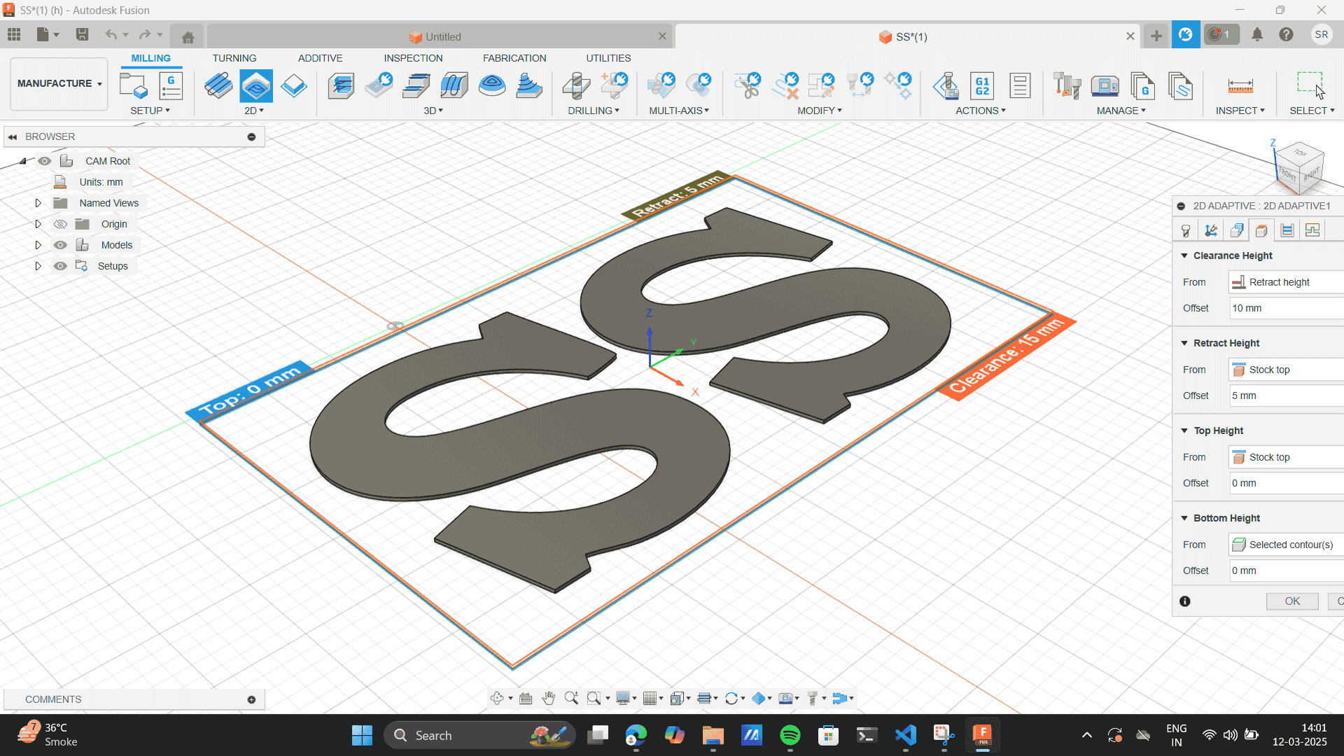
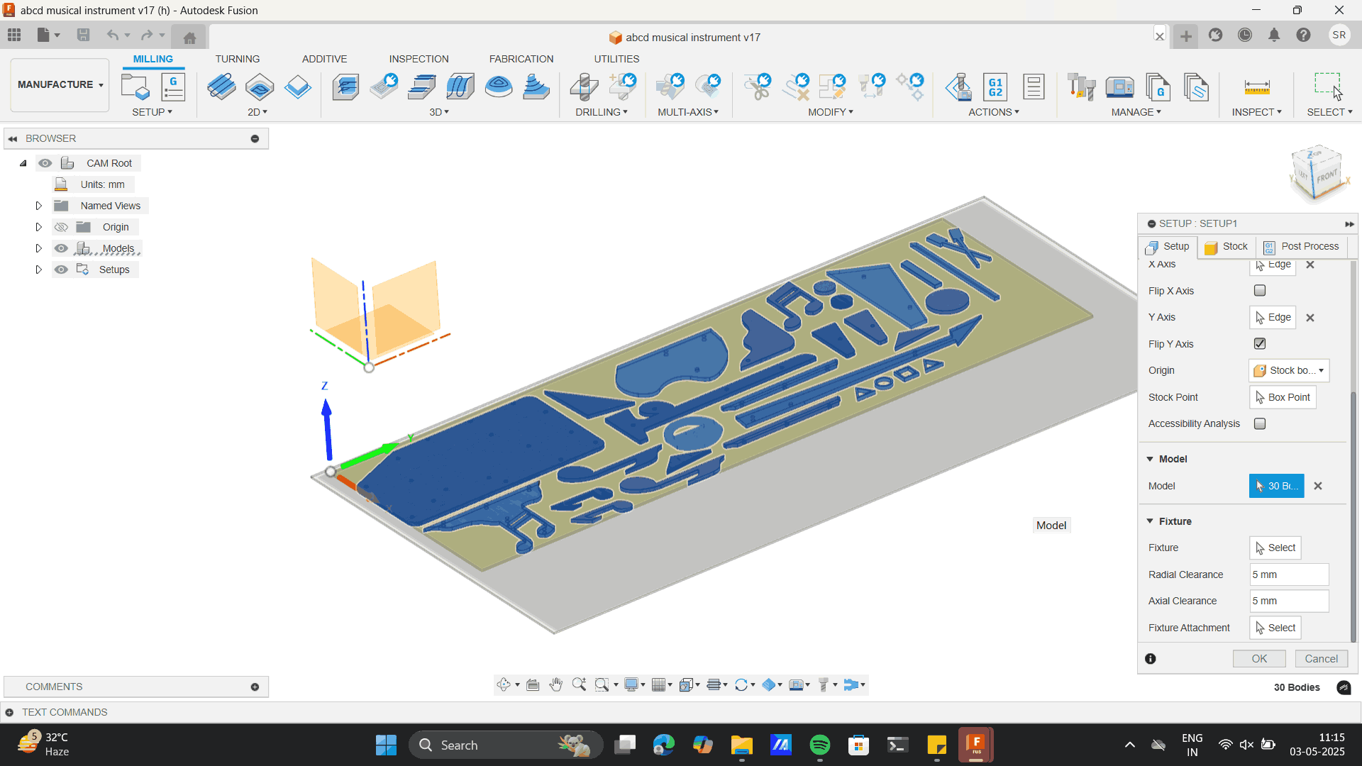
Once the design was ready Change from design mode to manufacturing mode.
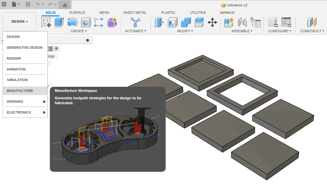
Set-up> New Set-up.
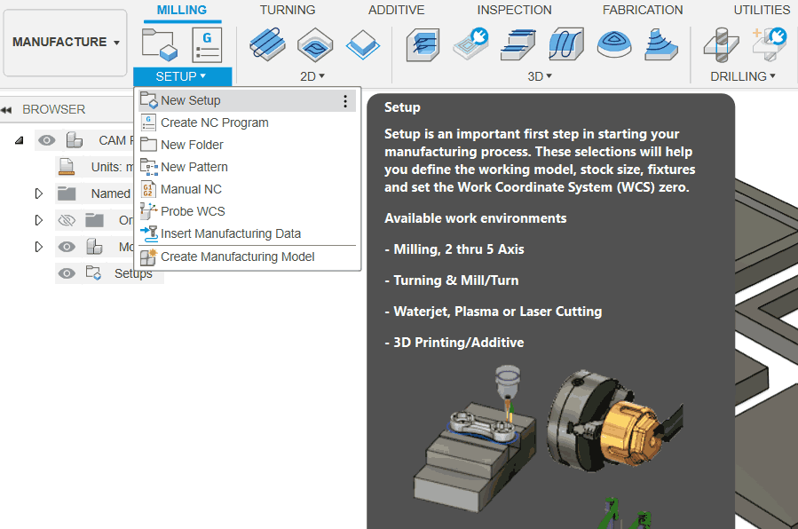
Set-up > Machine-
Autodesk Generic 3 axis.
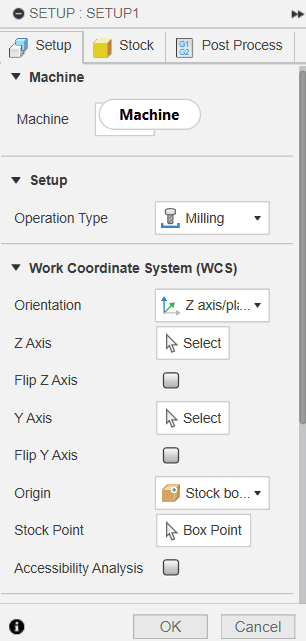
Select orientation as per model.
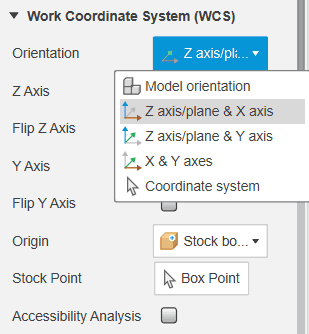
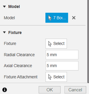
Scroll down in the set to select the model.
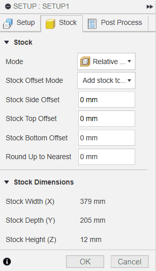
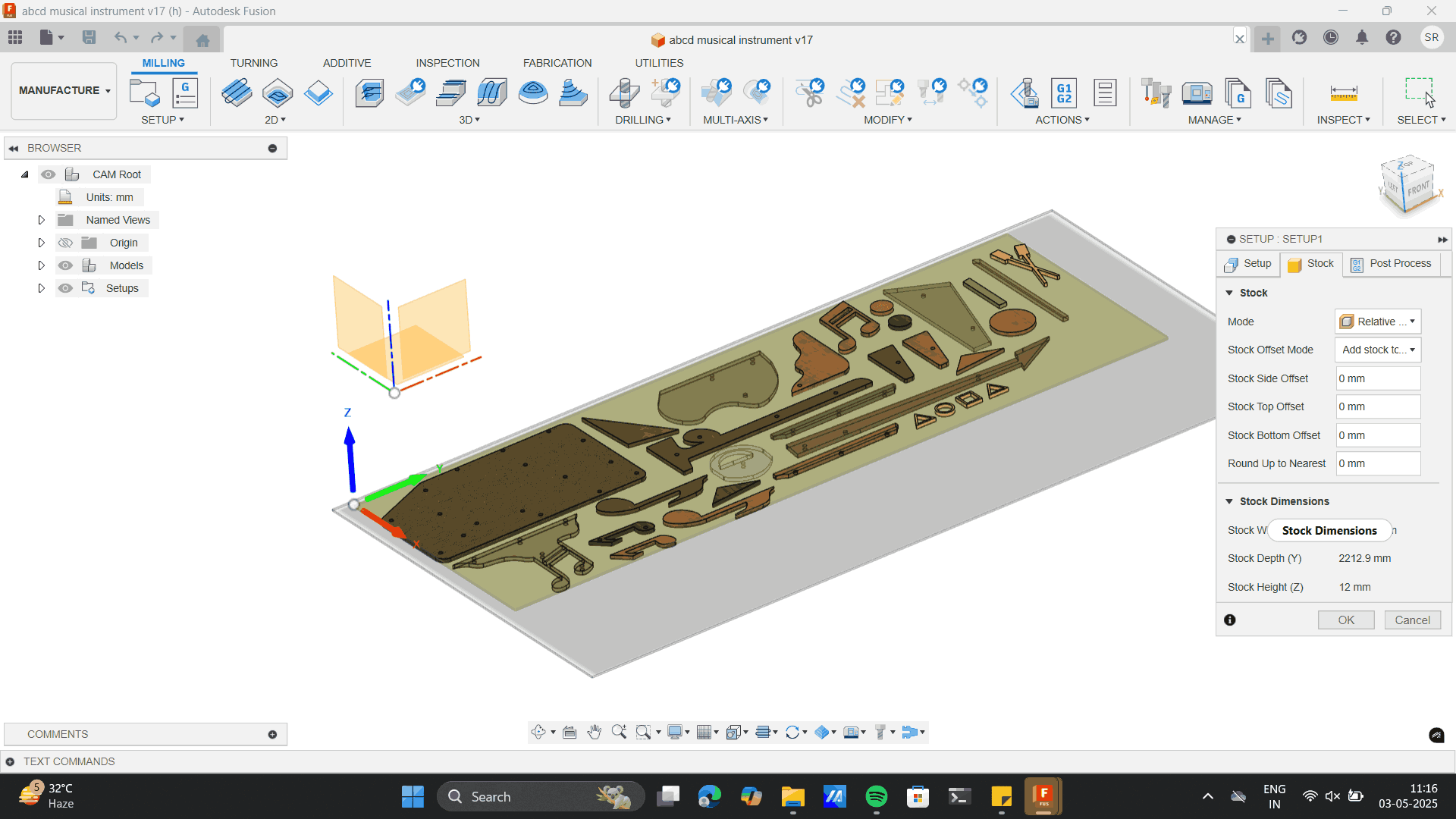
In stock, do the below settings.
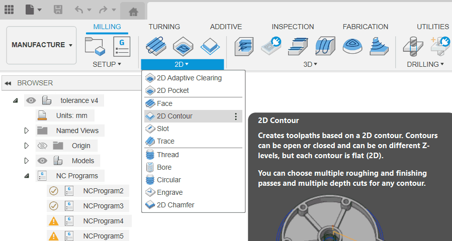
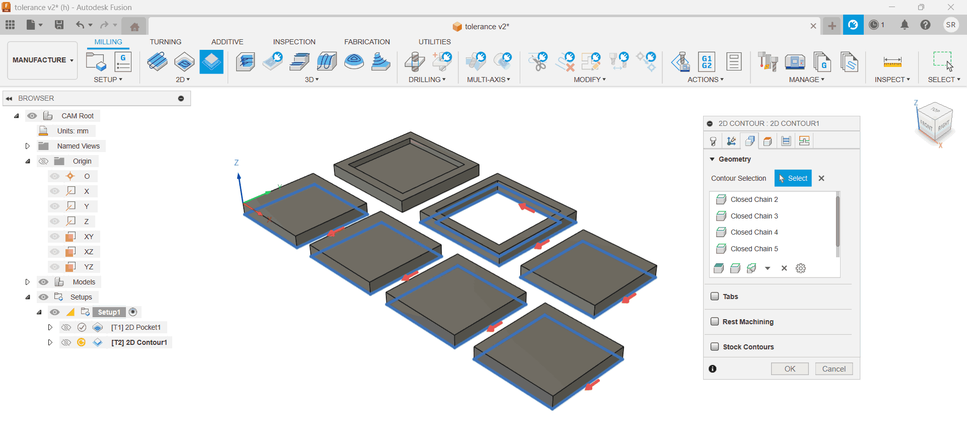
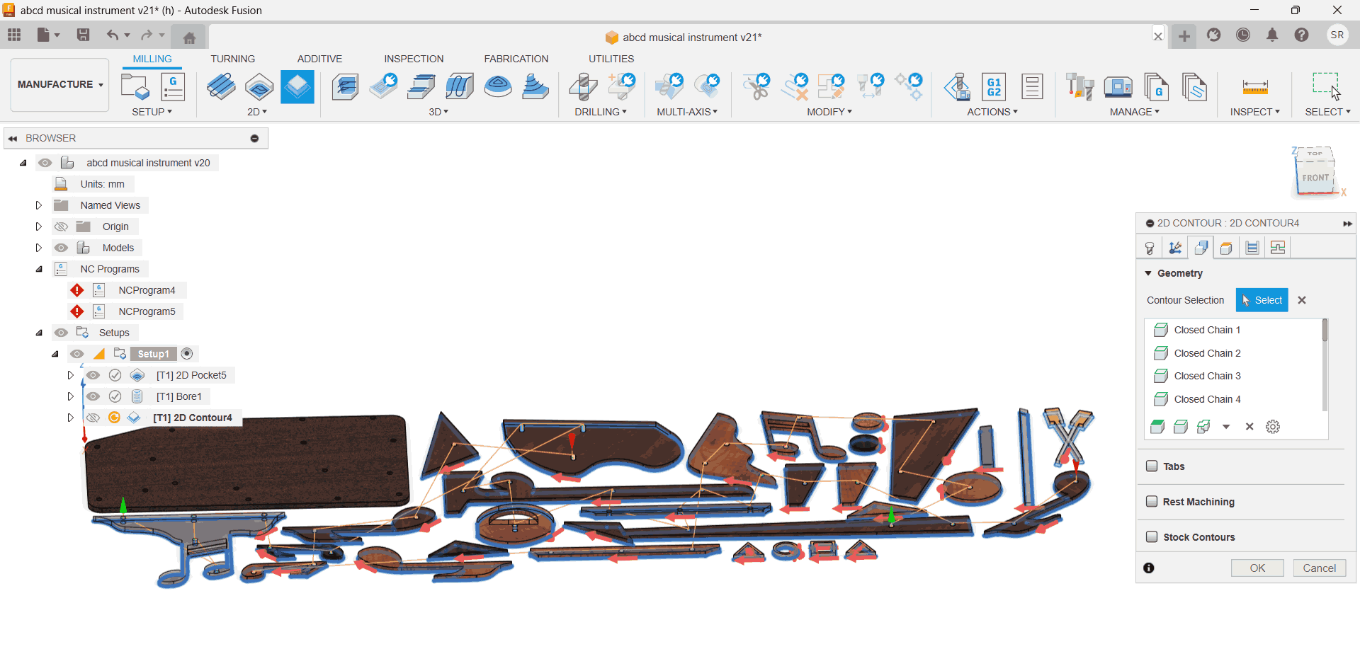
Select 2D Contour for through cuts.
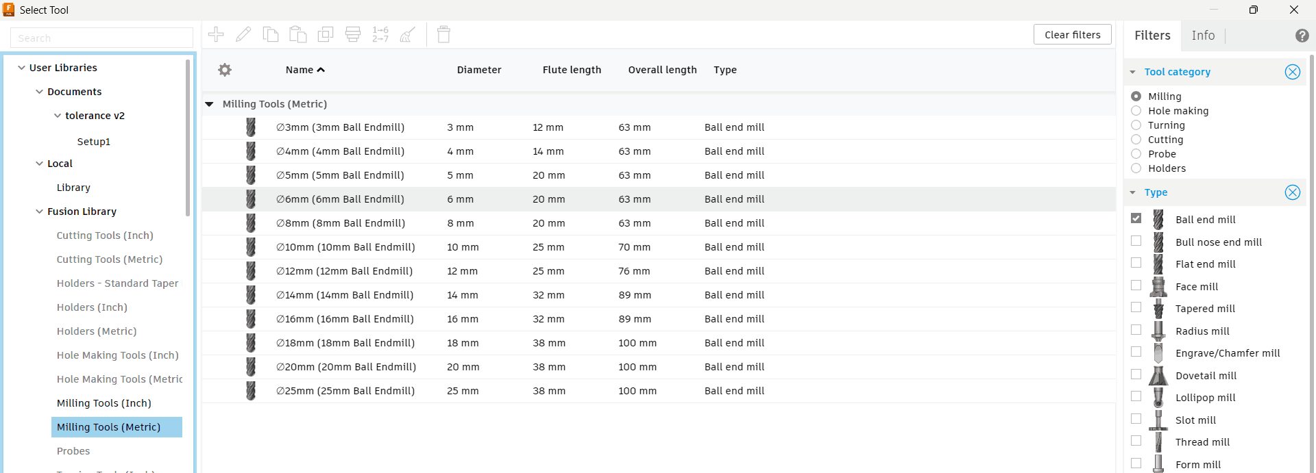
Select tool as ball end mill 6mm
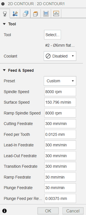
Do the below settings
In geometry> Select chain countours.
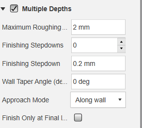
In heights, do the below settings
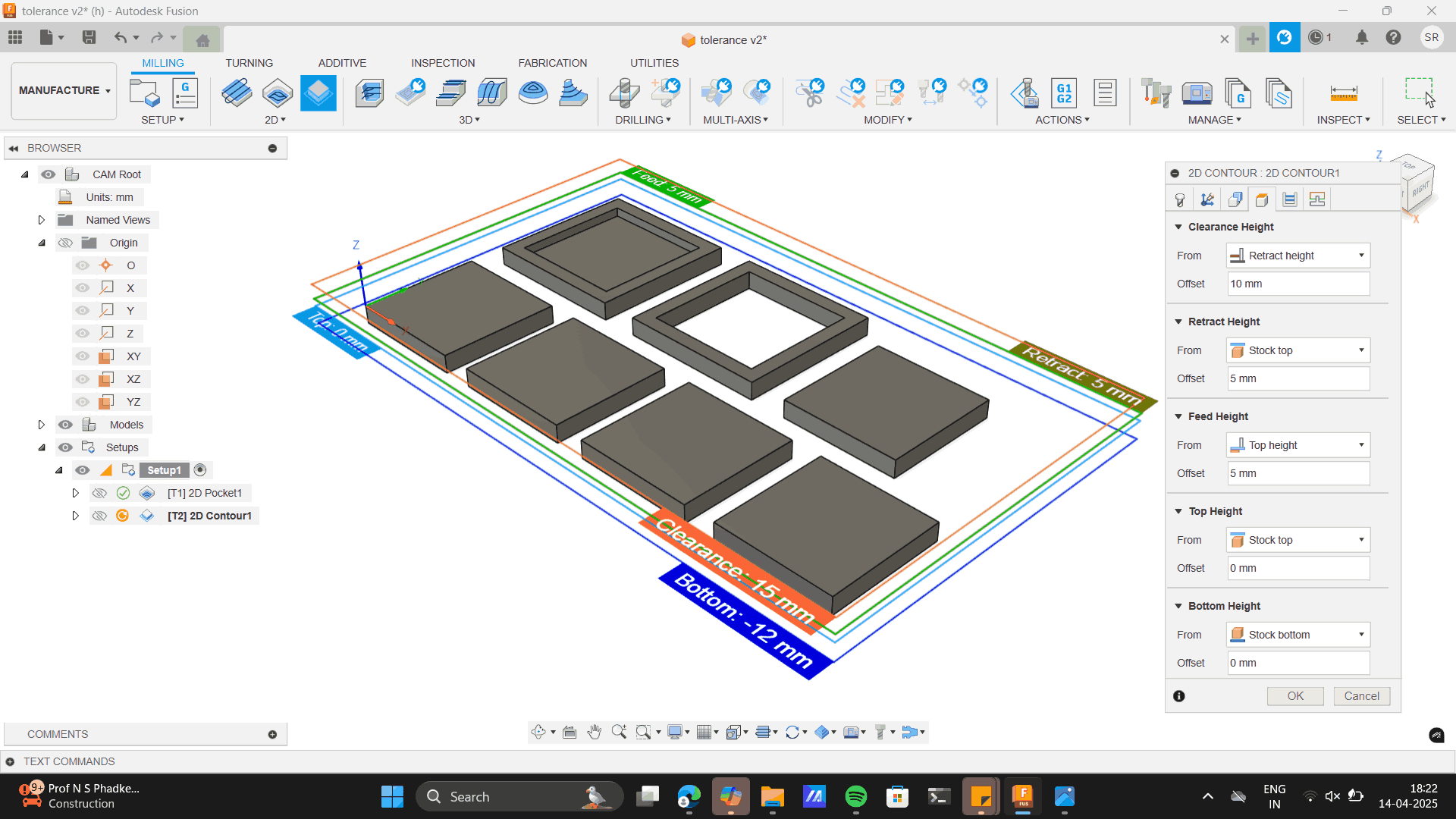
Finally in passes select Multi-depths and hit OK.
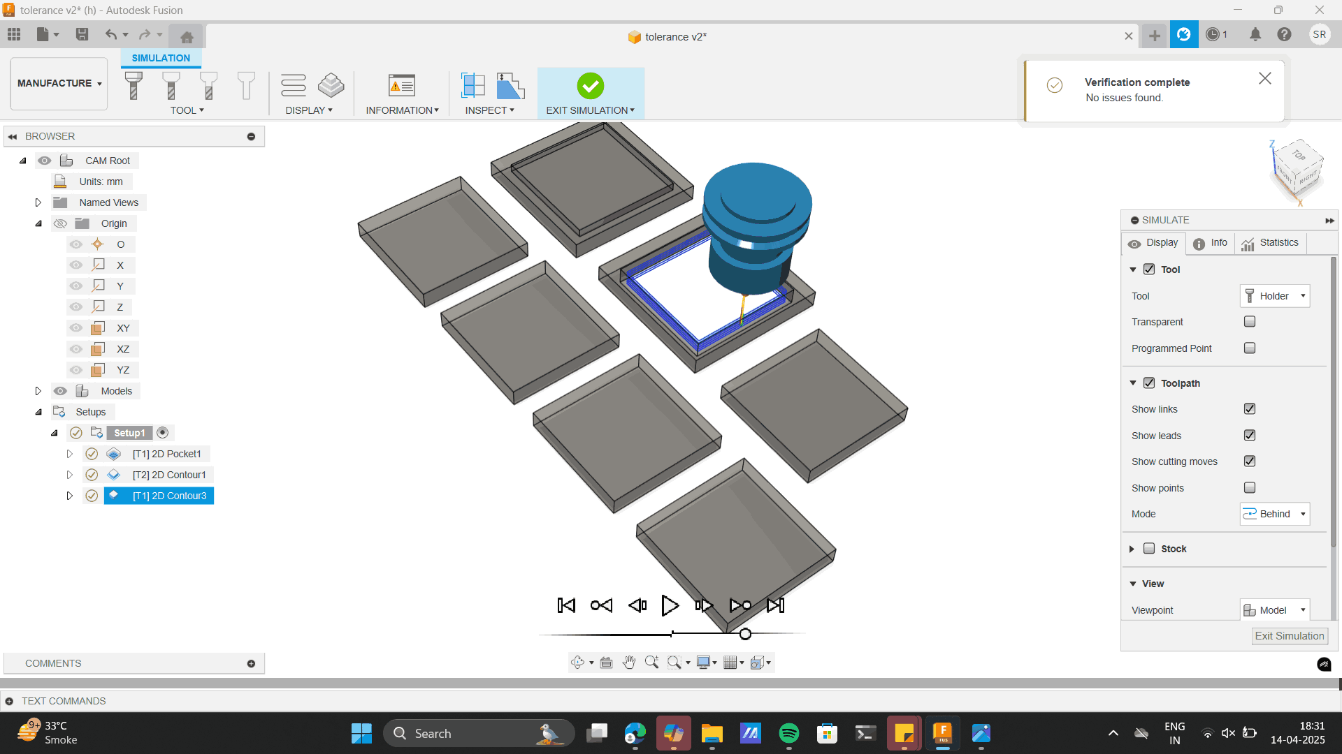
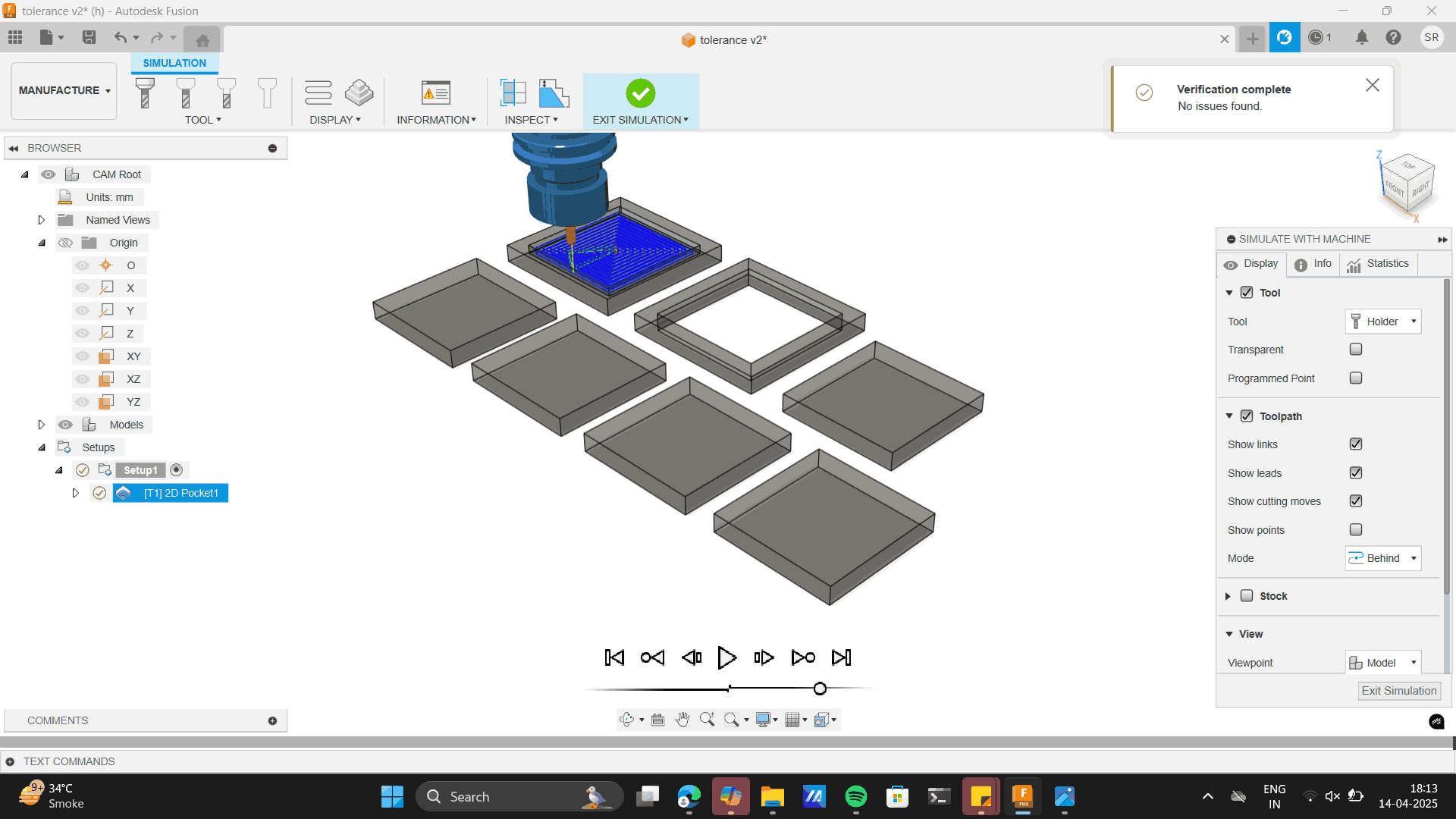
Once all the settings are done, simulate to check errors.
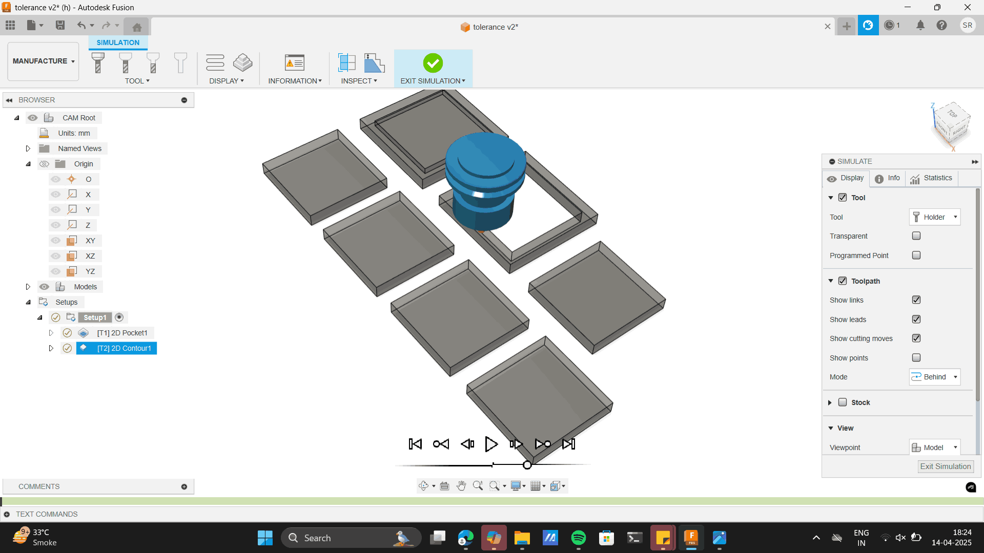
This will verify and check for errors.
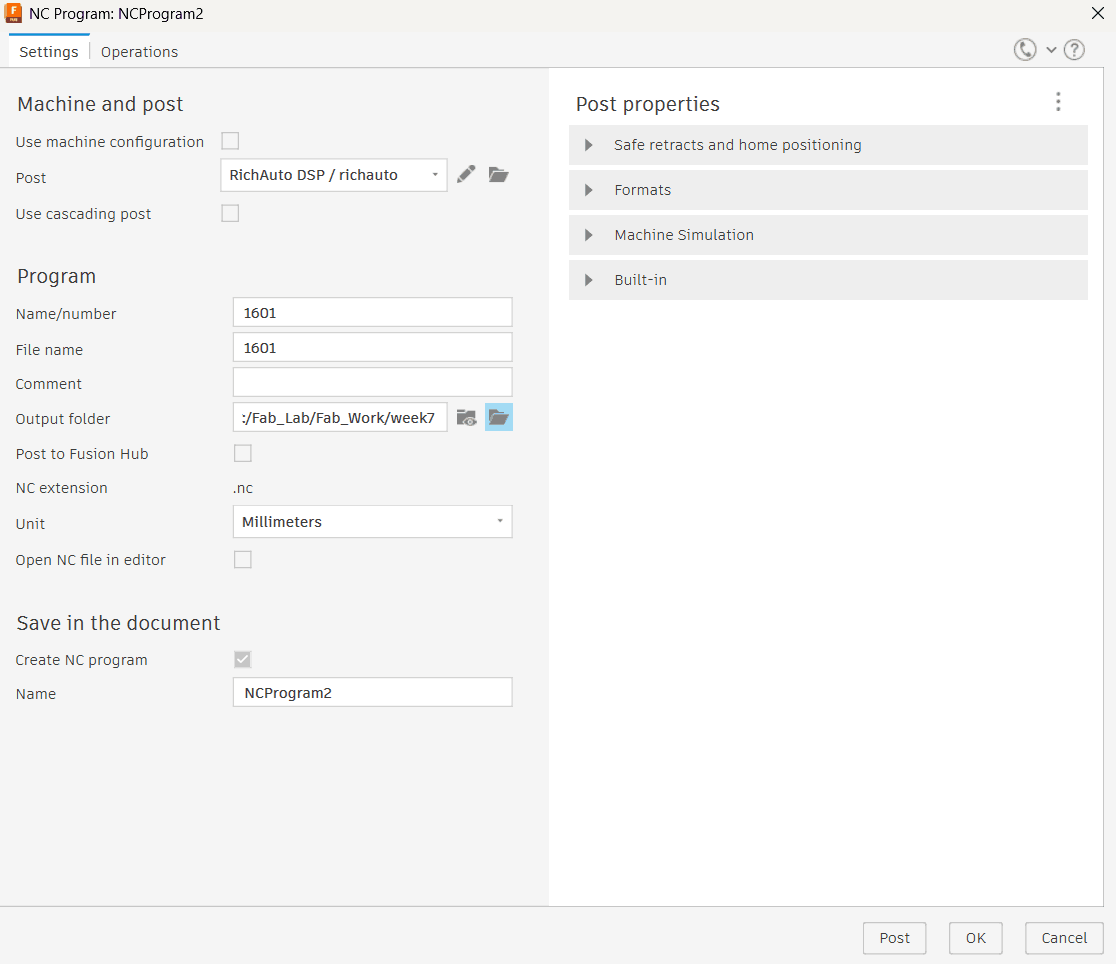
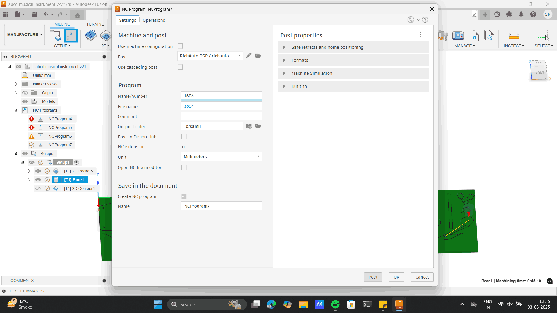
Now export the g code by the below steps.
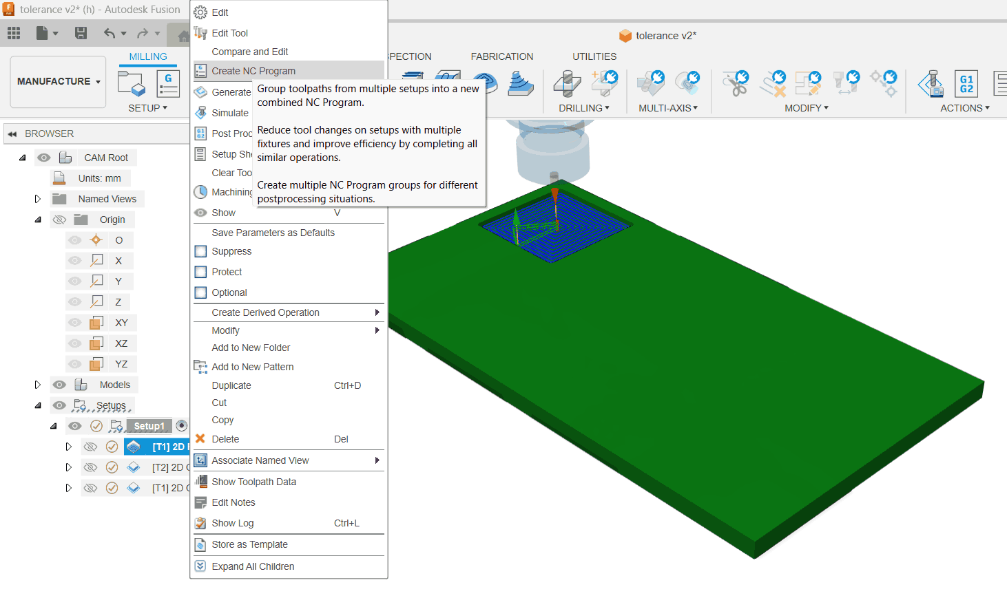
Name the file in 4 digits.
Do the similar above settings for 2d pocket. 2D pocket is to cut pcokets as of the first piece in the model
above.
Learnings: Always do the 2d pocket setting before the 2d contours, As doing the 2d pocket after 2d contour
where
the piece is cut can move the pice while doing the internal 2d pockets.
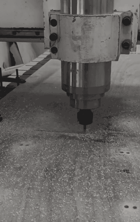
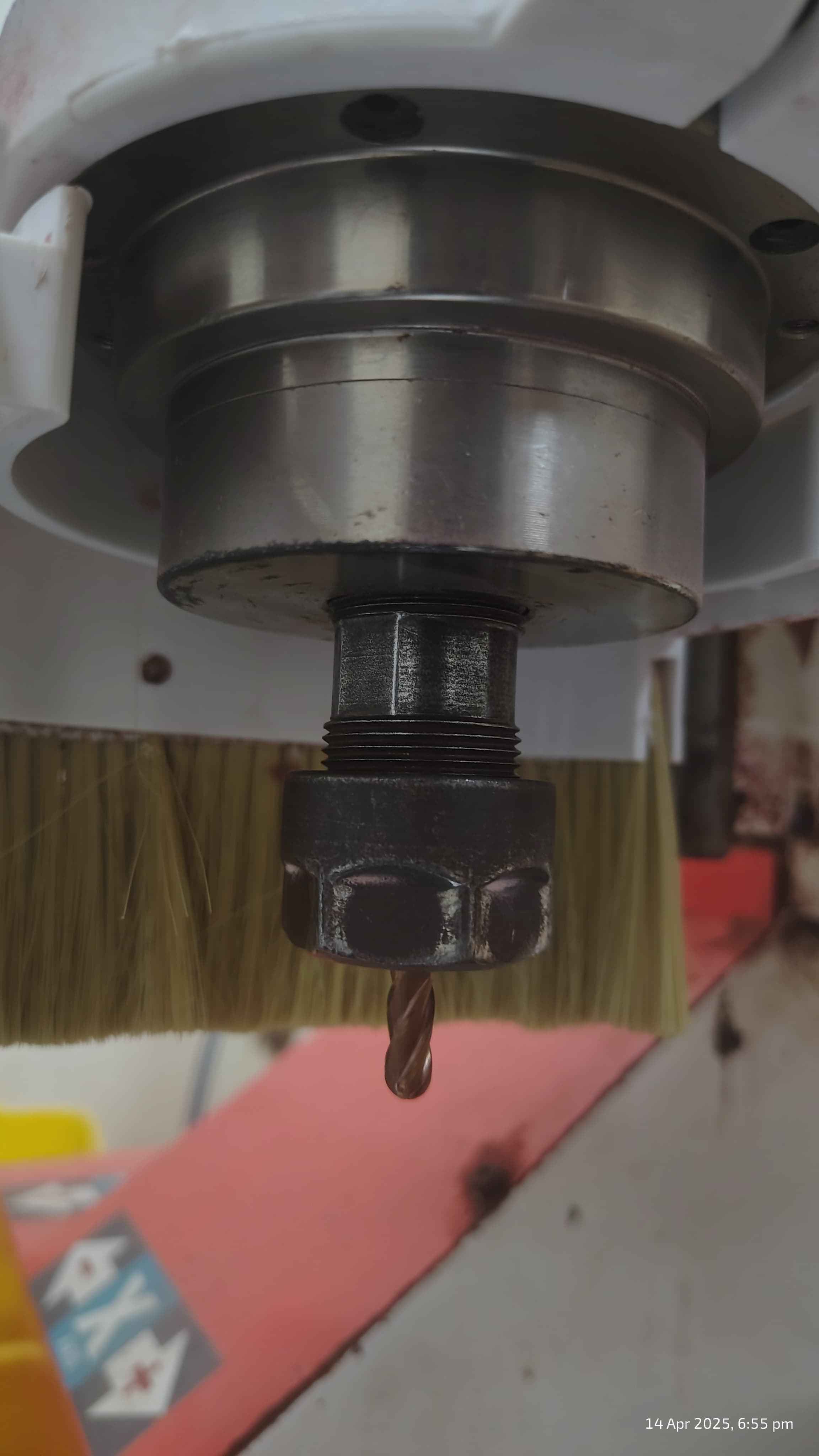
Machining
6mm Ball flat end mill.
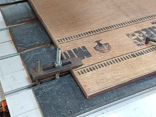
Setting up clamps
Learnings: The Ball end mill always give a fillet while cutting. Thus the sharp egde I gave to my square
shapes while designing
would be cut in curves, this did not affect my current cutting process as I was only checking tolerances,
thus every sharpe edge would be cut as a fillet.
However, it was a learning to the further design process I would go about.
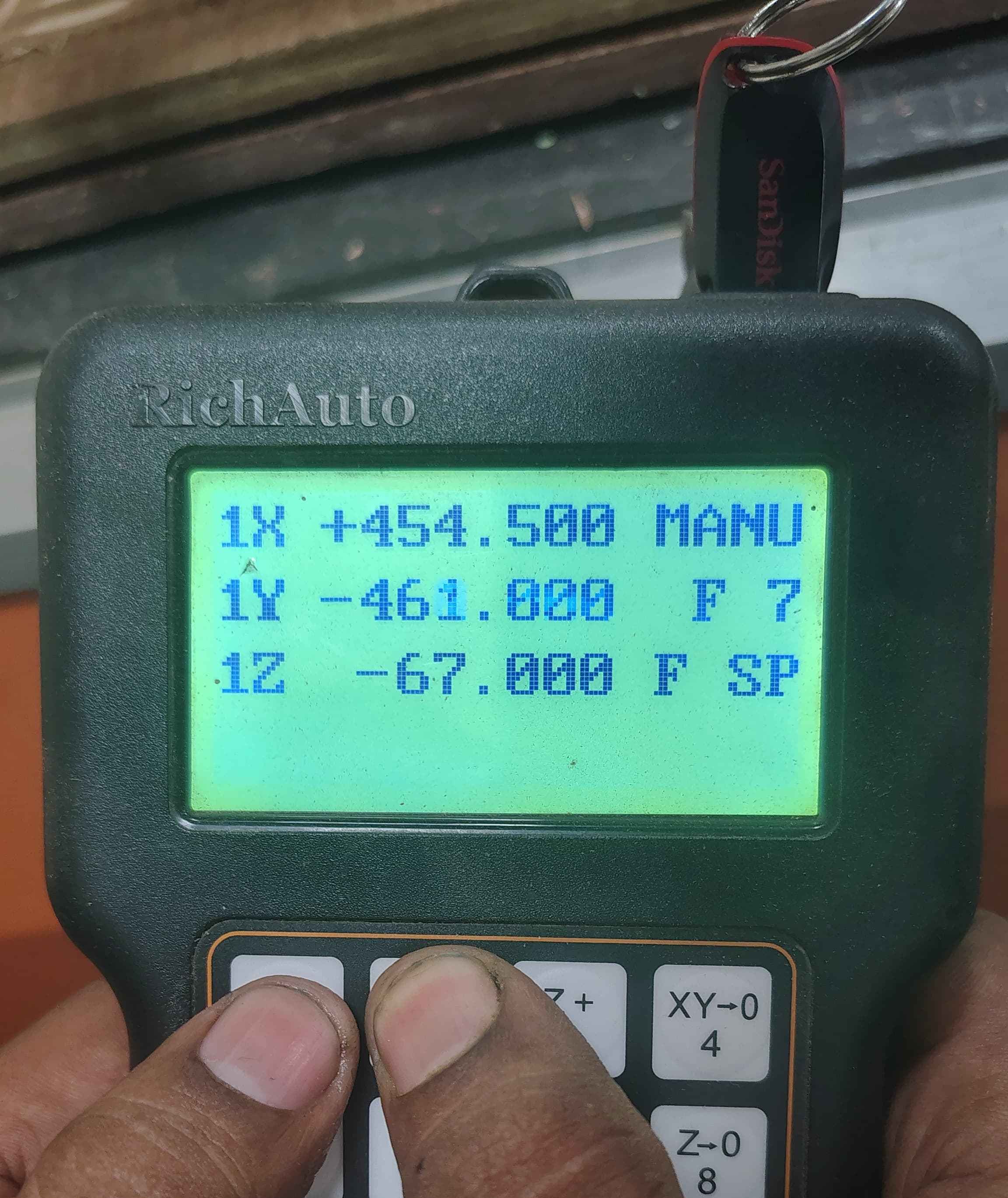
Setting X-Y-Z axis as origin
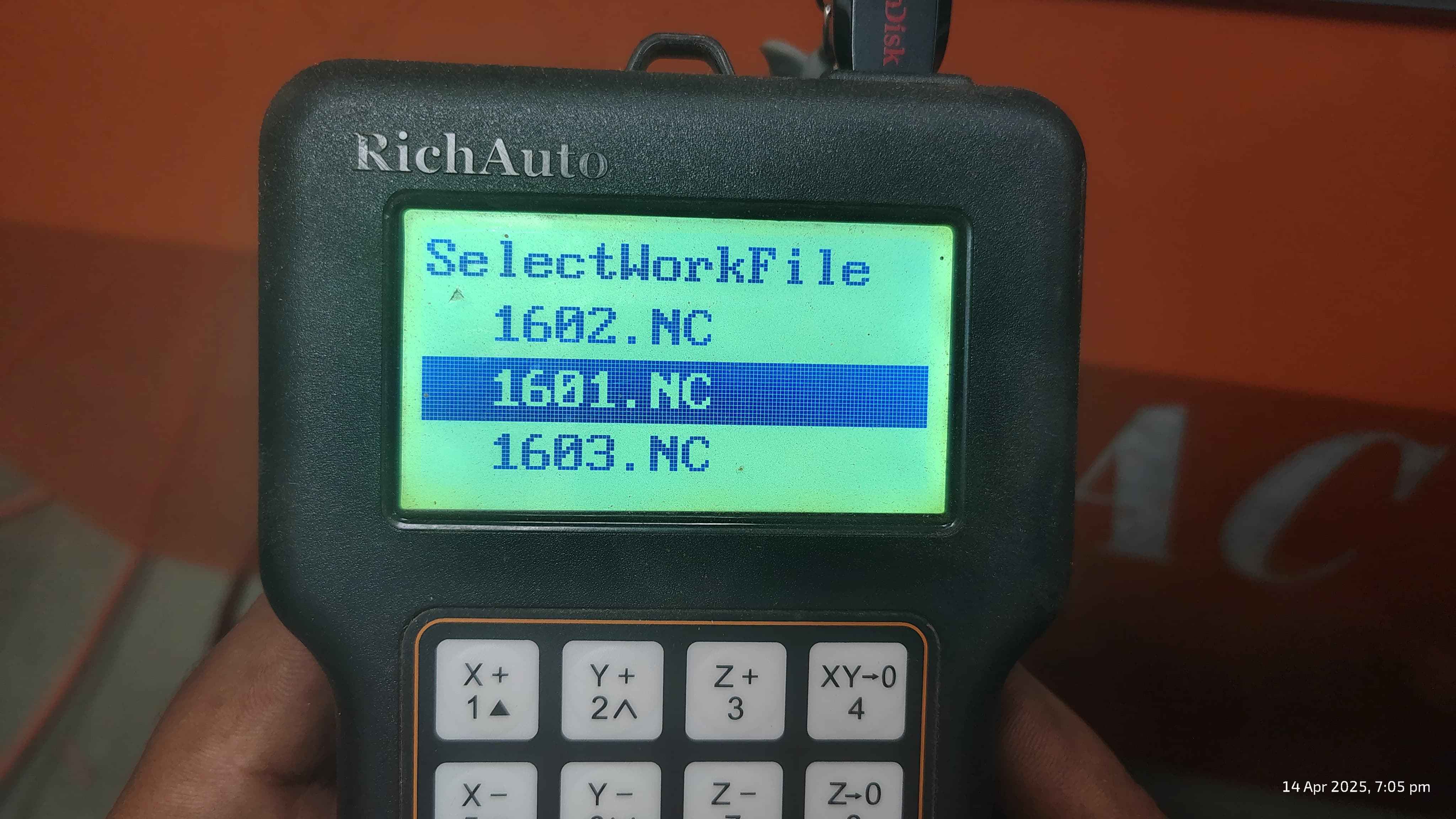
Selecting the file.
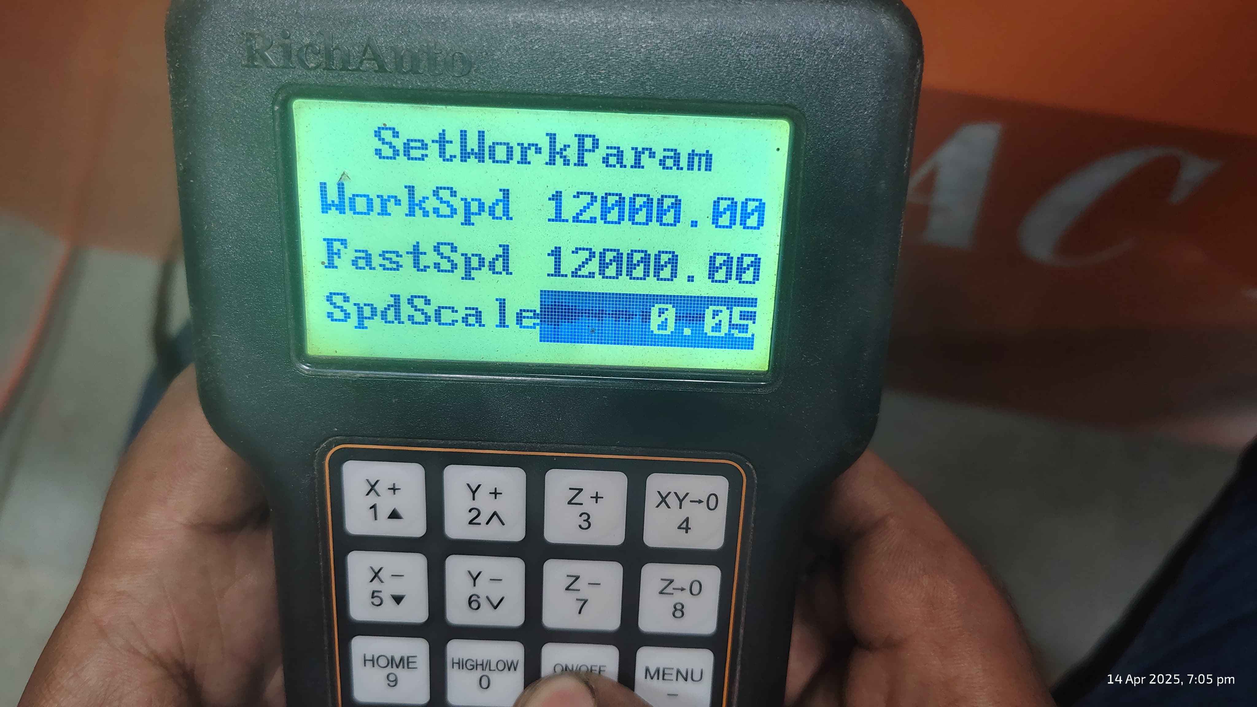
Setting the speed scale as 0.5 which was a constant for out machine.
Milling the pieces
Cut Pieces
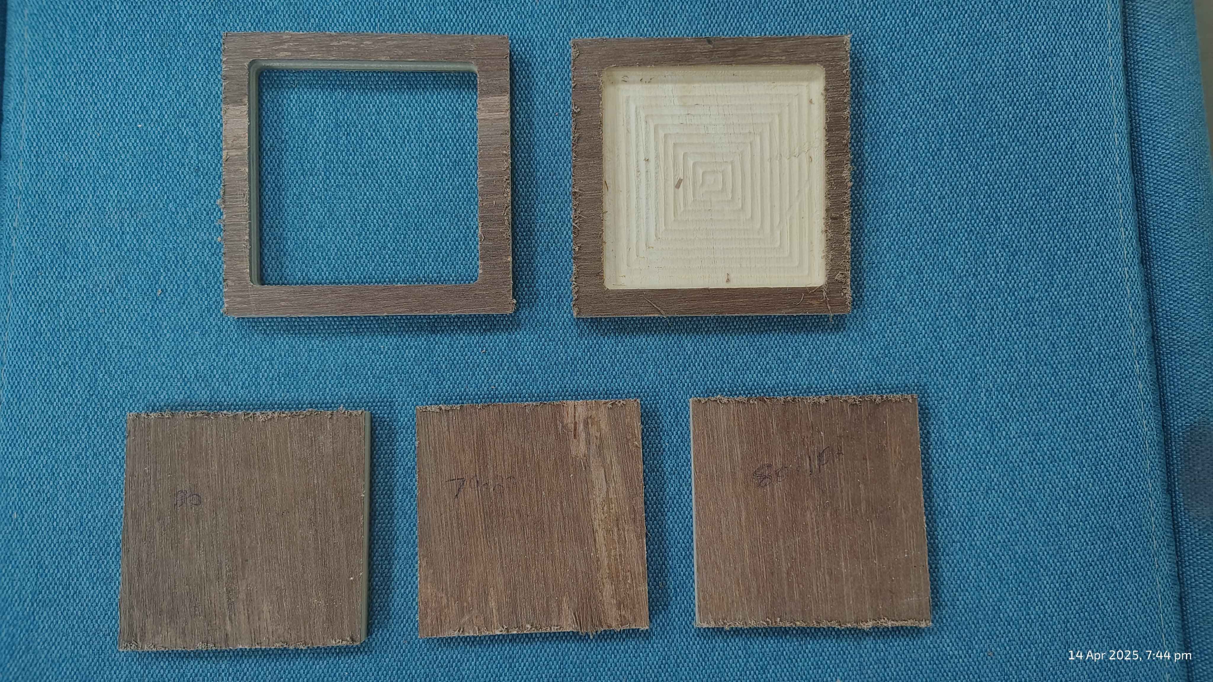
I tried fitting pieces all pieces from the bottom pieces to the top and check the fit check. I wanted a
friction fit
With every piece being a fit, the piece 79.80 was a perfect friction for the 80mm through hole and pocket
squares.
Dowel support
Moving forward with the dowel support in my design
I sketched circles of 12mm connecting to the top layers on the base.
I extruded and and cut the layers at 6mm ie half of the material length from the top and bottom most
layer.
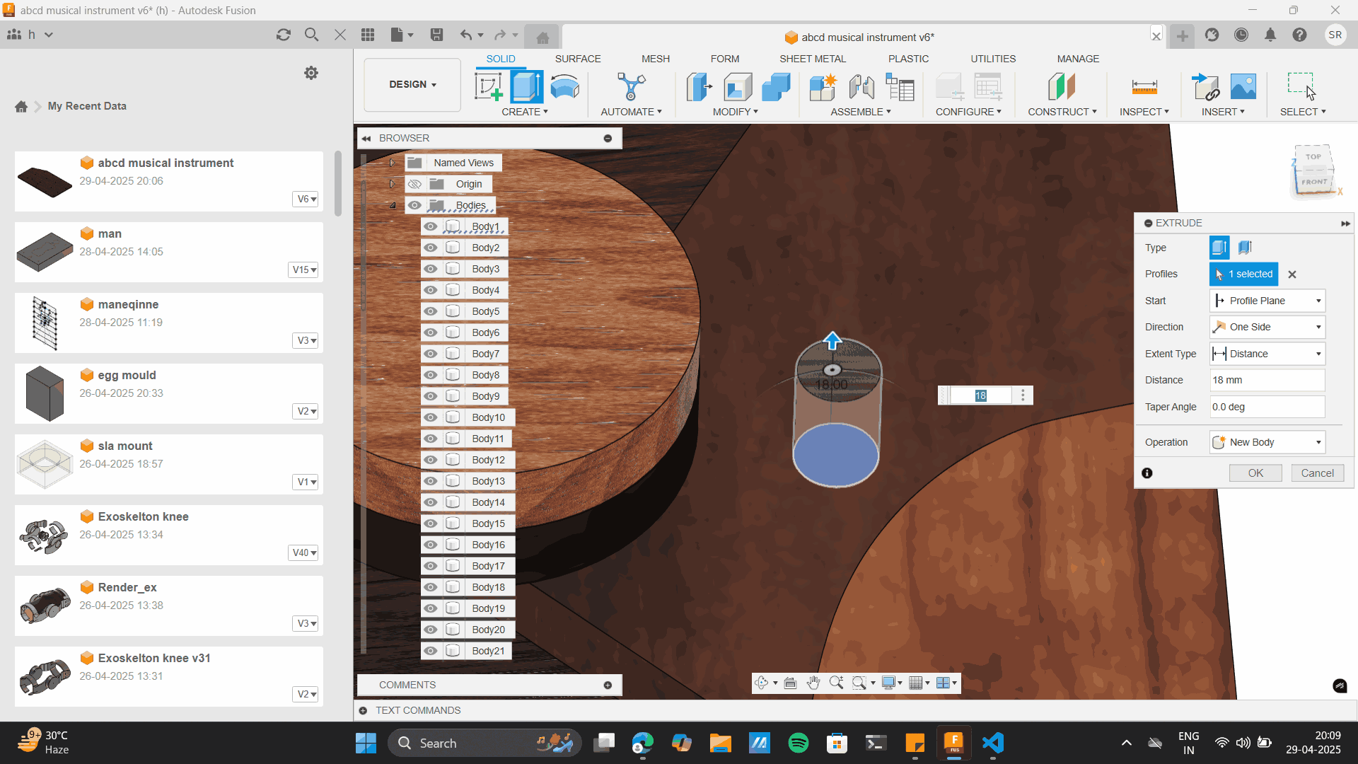
I gave a through cut in the centre layers
The idea is to add to 11.8 mm dowels to these pockets I have created.

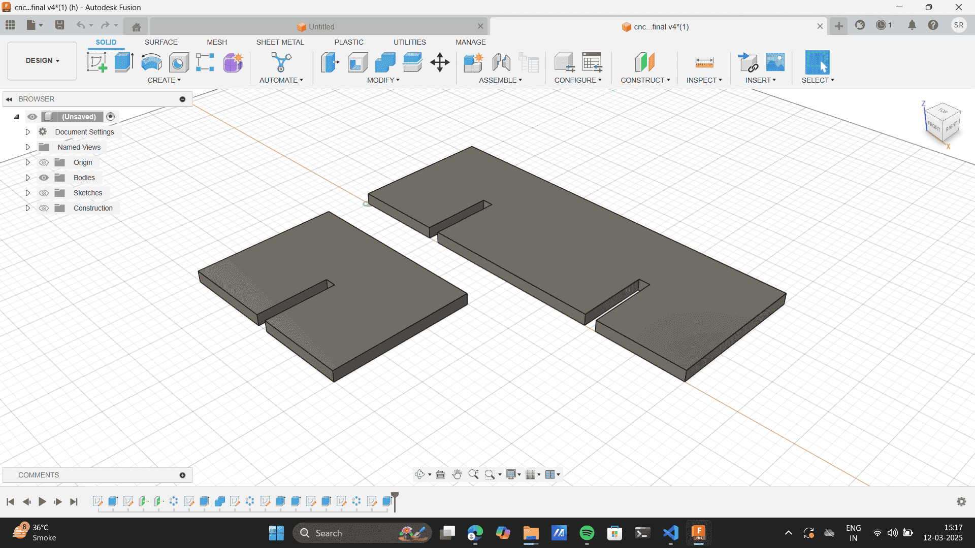
CNC layout
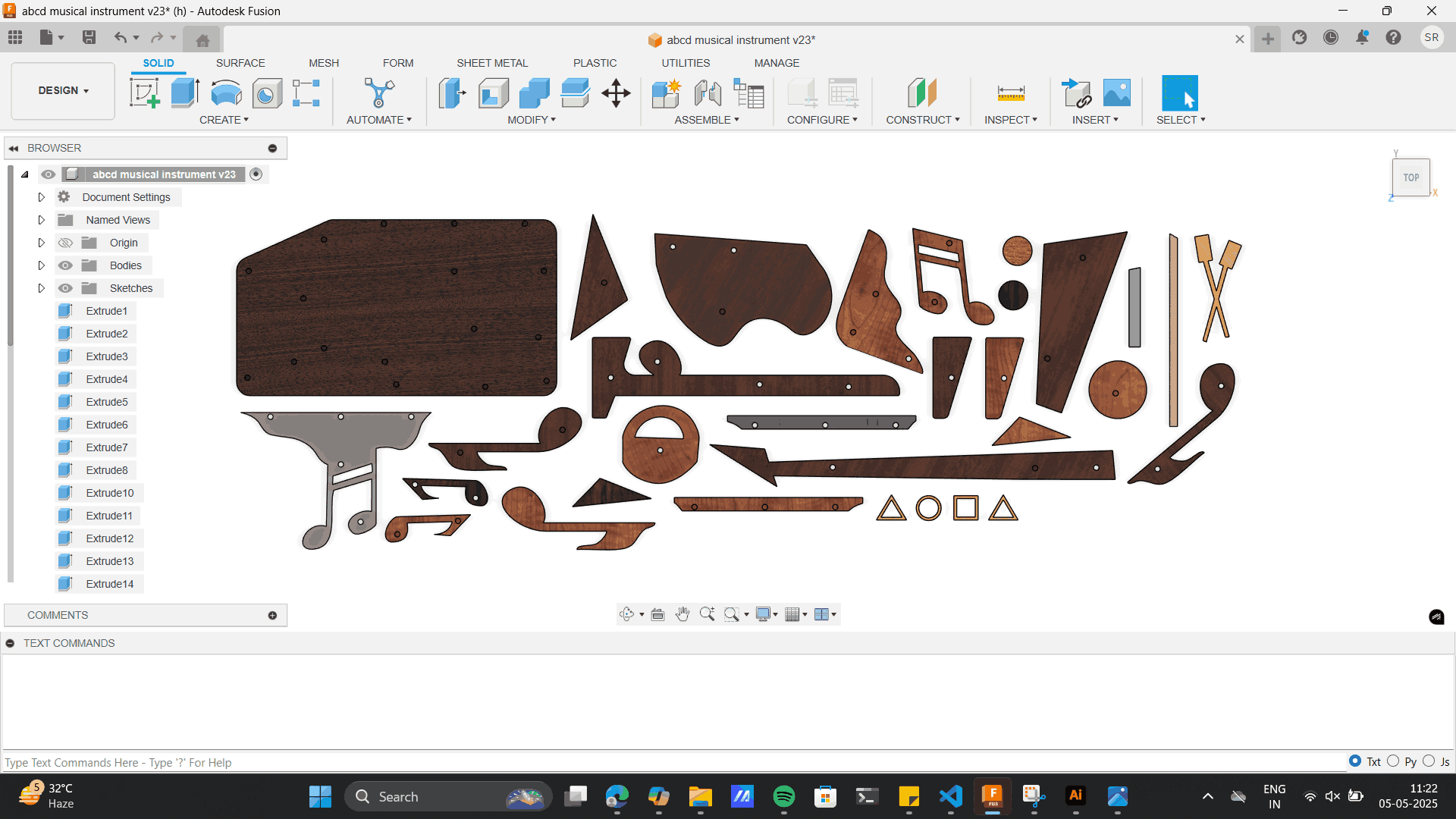
The next step is to layout each model piece on an 8*4 ft sheet which is the bed size of the CNC machine. Thus
I took each piece from the whole model and aligned
it to the top surface of the 8*4 sheet size. The material I used was 12 mm play. which is the thickness I
gave to my aligning base layer. I used the move tool to
move each piece to set the layout. The distance I gave between each piece was around 12mm, this was
considering the tool width radius of 6 mm that would be cut on the
exterior layer of the piece. As I moved each piece the layer of height of every layer was different which I
had to align manually. To the base layer to align each piece to the same height.
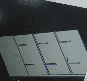
Moving and aligneing layers to a base of 8*4 ft.
Final Layout
Learning: As you can see in the top right image, Some of the pieces I layout were reverse of the pocket hole
which I set for the dowel thus, I had to flip it, where the dowel pocket would come at the top surface, the
updates layout was:
Manufacturing
Just like the previous CNC setup I used to check tolerances, I followed a similar process for the musical
file.
A new feature I learned during this process was 'Bore', which I will elaborate on below.
For detailed settings, you can refer to the earlier description under the friction fit section — here, I’m
providing only an overview of my process.
Selecting tool: 6mm flat end mill.
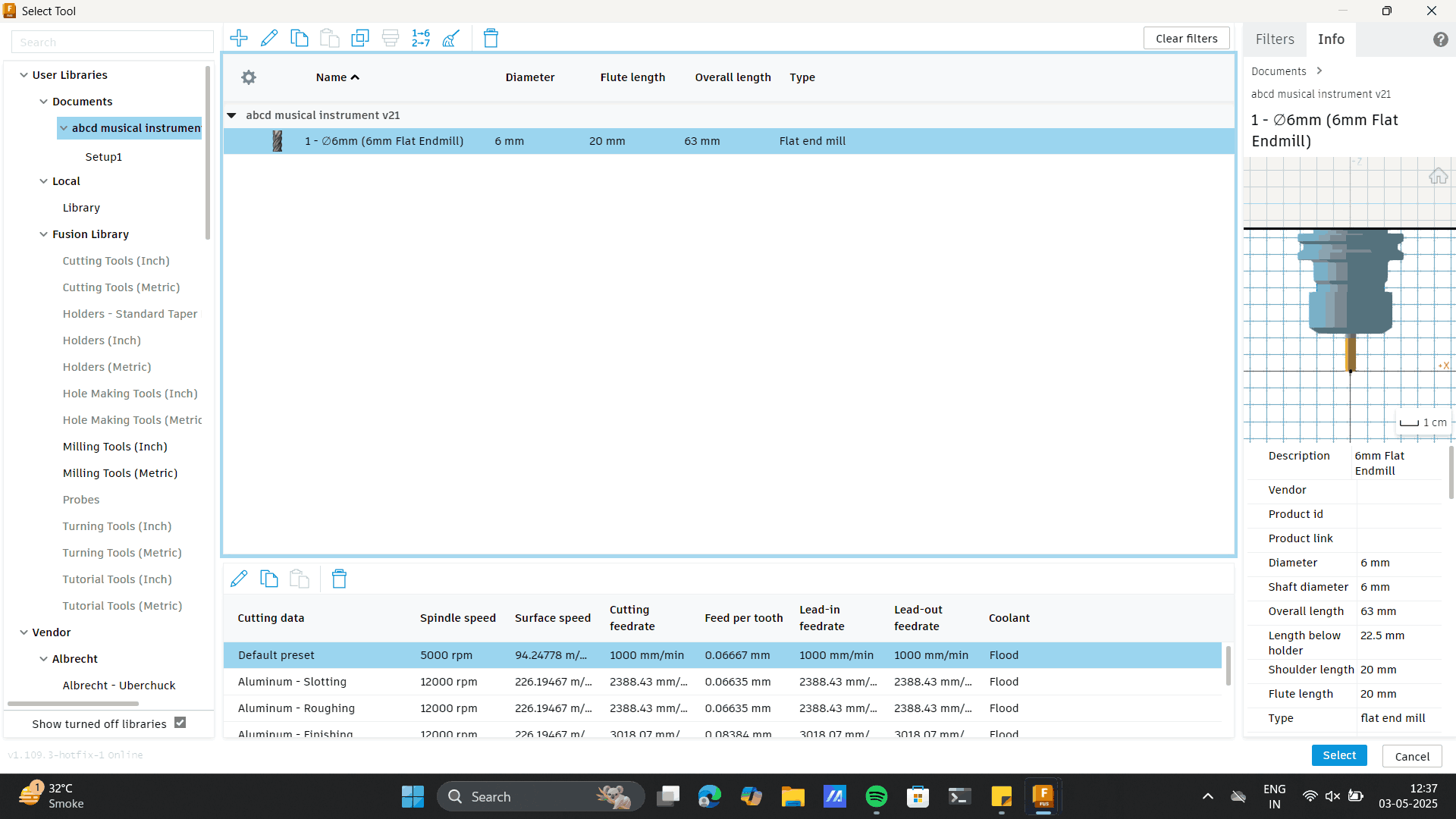
Setting up origin.
.png)
Selecting each model piece
Other machine setup settings.
Selecting each model piece
Other machine setup settings.
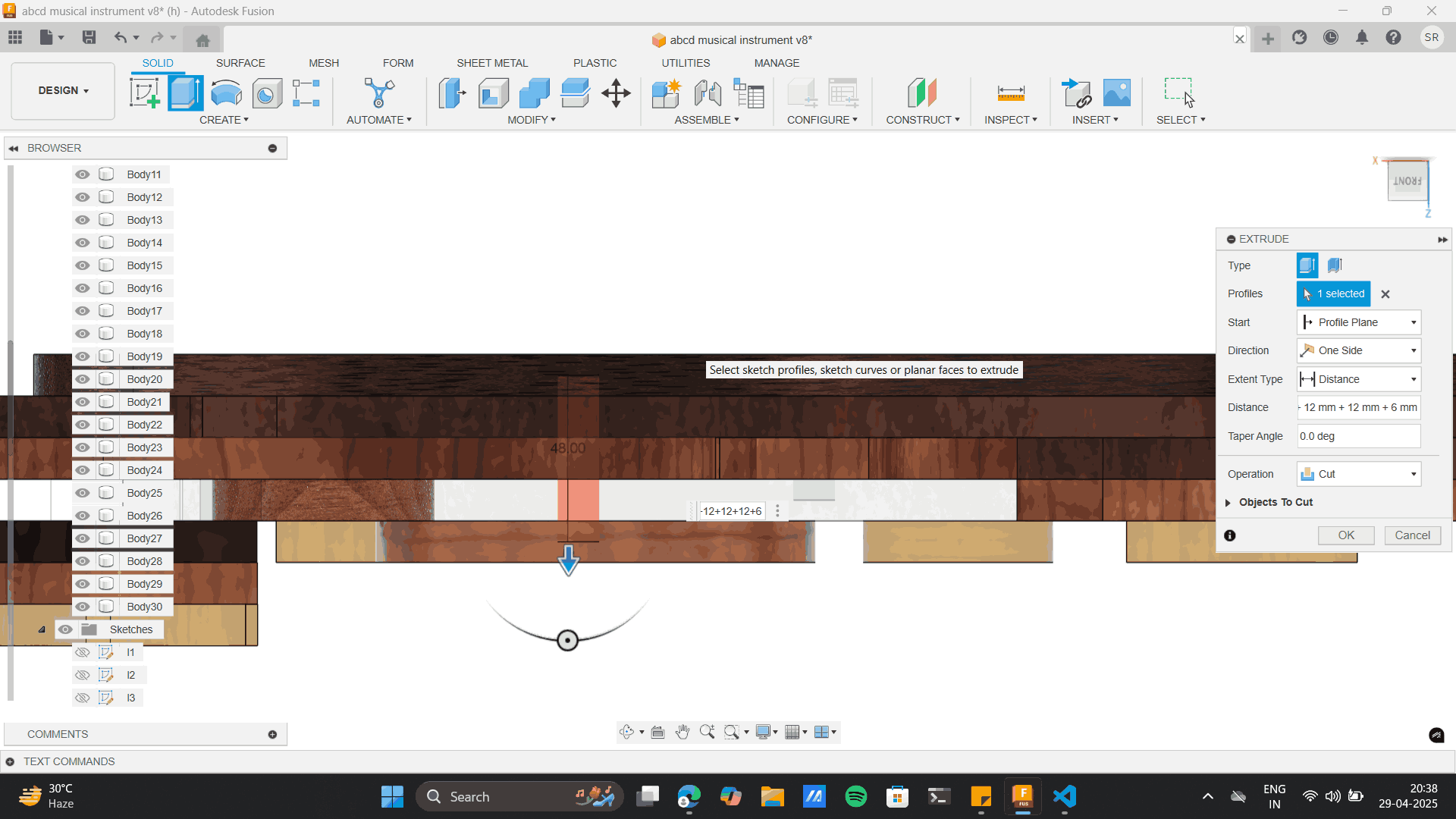
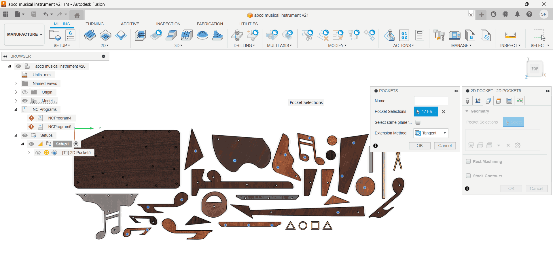
>2D Pocket Toolpath Setup. It removes material within an enclosed area (like a pocket or cavity), but
does not cut along the outer edge like a 2D contour. This setting I used for the half cut holes I made for
the topmost and the bottomost
piece of the dowel.
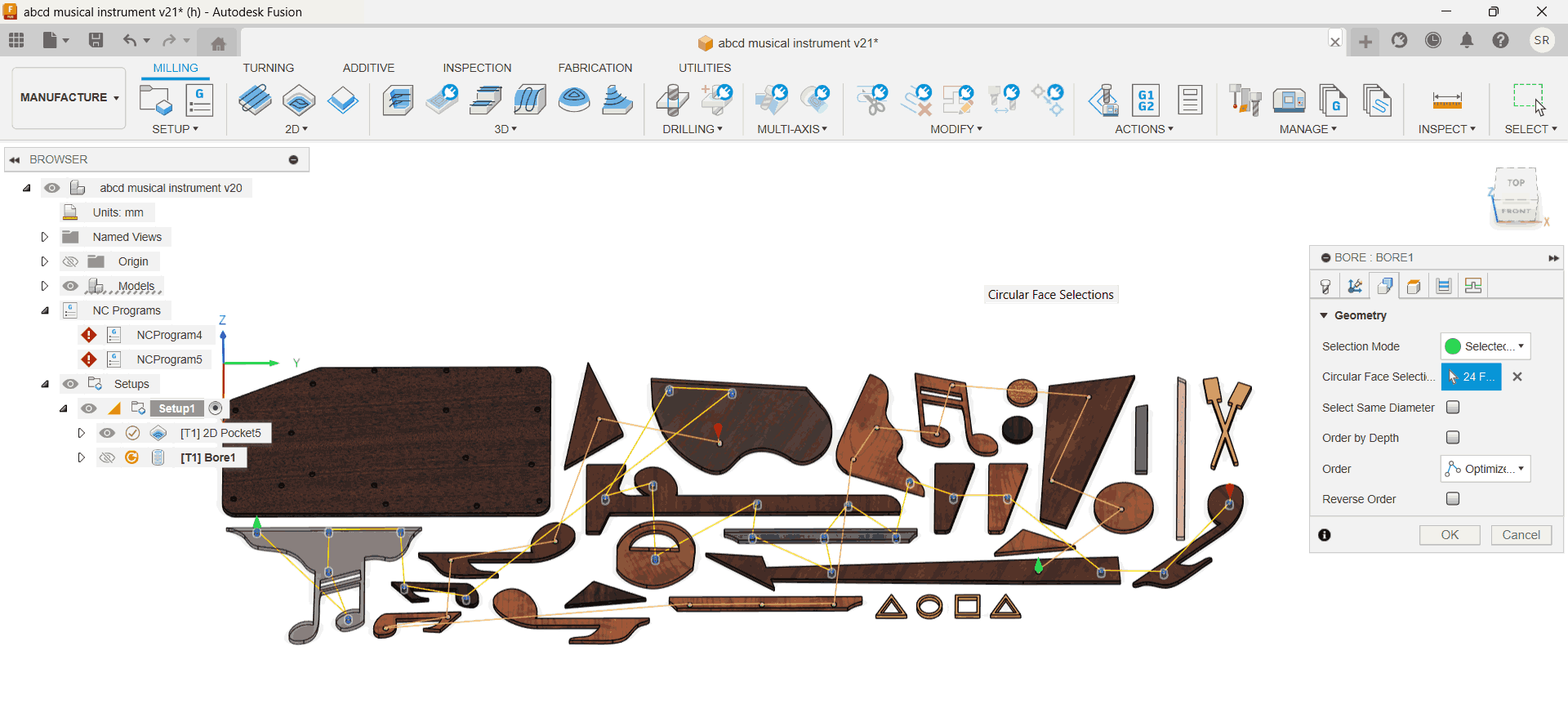
2D Bore Toolpath Setup.It helps in creating accurate circular holes with smooth internal surfaces. I
used this set-up for
the through hole dowels which are the centre pieces sandwiched between the top and bottom layer which gave
me
tight tolerance fits, like those needed for my dowel pins which will act like press-fit parts.
2D Contour Toolpath Setup.It is used to define the fundamental machining and cutting parameters for
your job.
I used this to cut the boundaries cutouts for every piece other than the holes.
After simulating, I created an NC code for each of the above files
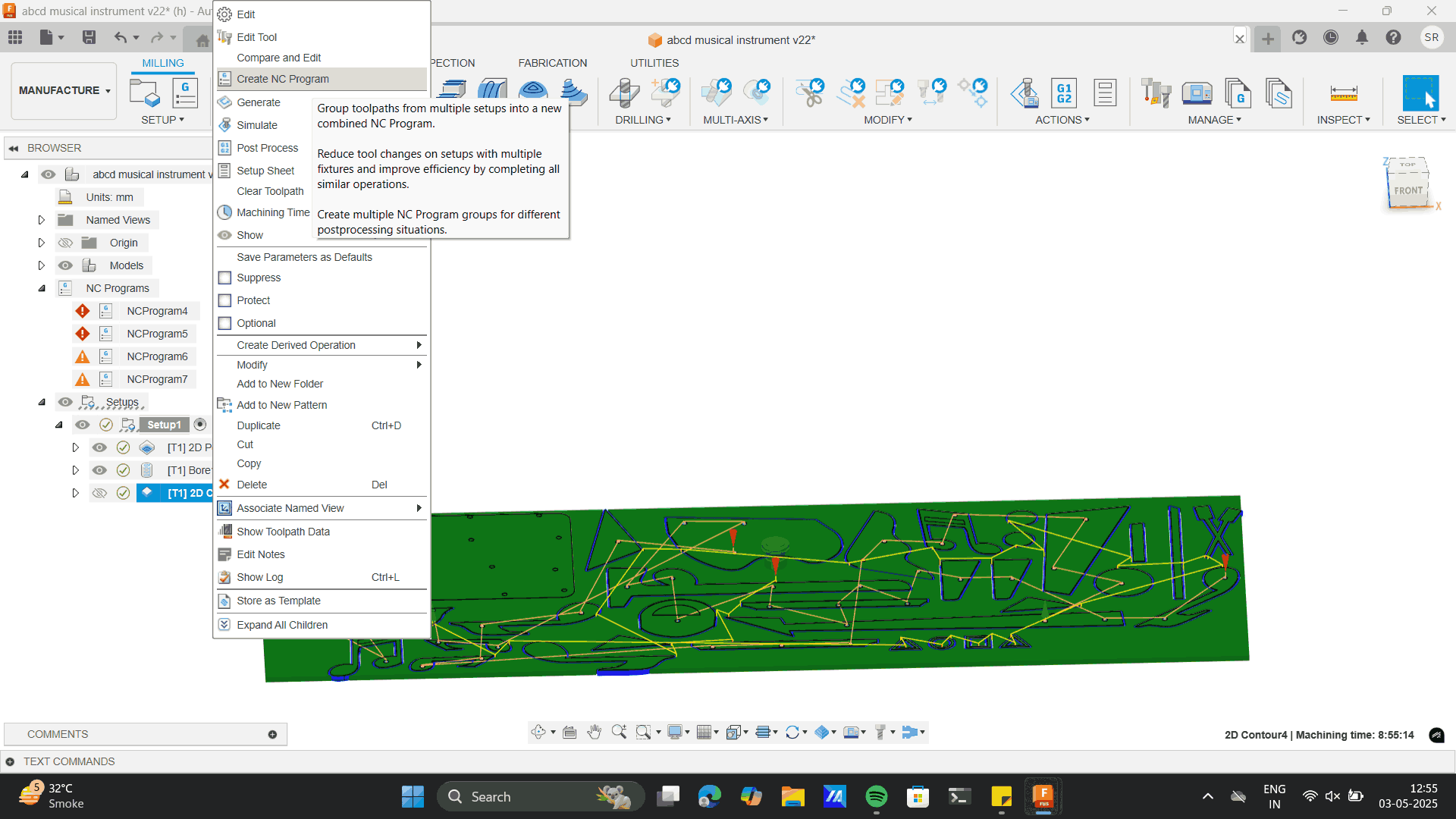
Exported Each file.
Production
Note: In CNC machining, pocket and bore operations should always be done before the 2D contour. This ensures
the part stays securely held in the stock while internal features are machined. Cutting the contour first
can loosen the part, causing vibrations, inaccuracies, or tool damage. Doing internal operations first
maintains stability and ensures clean, precise machining.
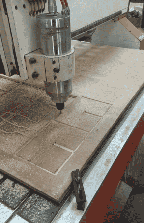
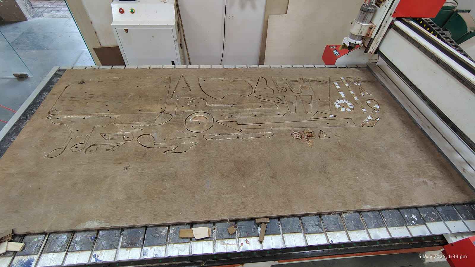
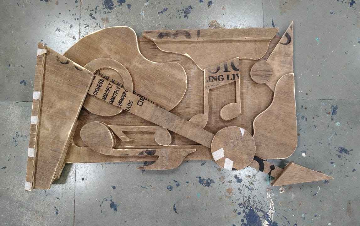
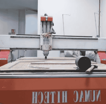
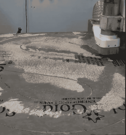
Image 1: The challenge in the above process was to
cut all the files in one go.
Previously, there were instances that the bit broke on continuous usage.
However, I learnt that with proper RPM and speed, all pieces can be cut at once.
Fun tick was, to decrease the speed at the curves.
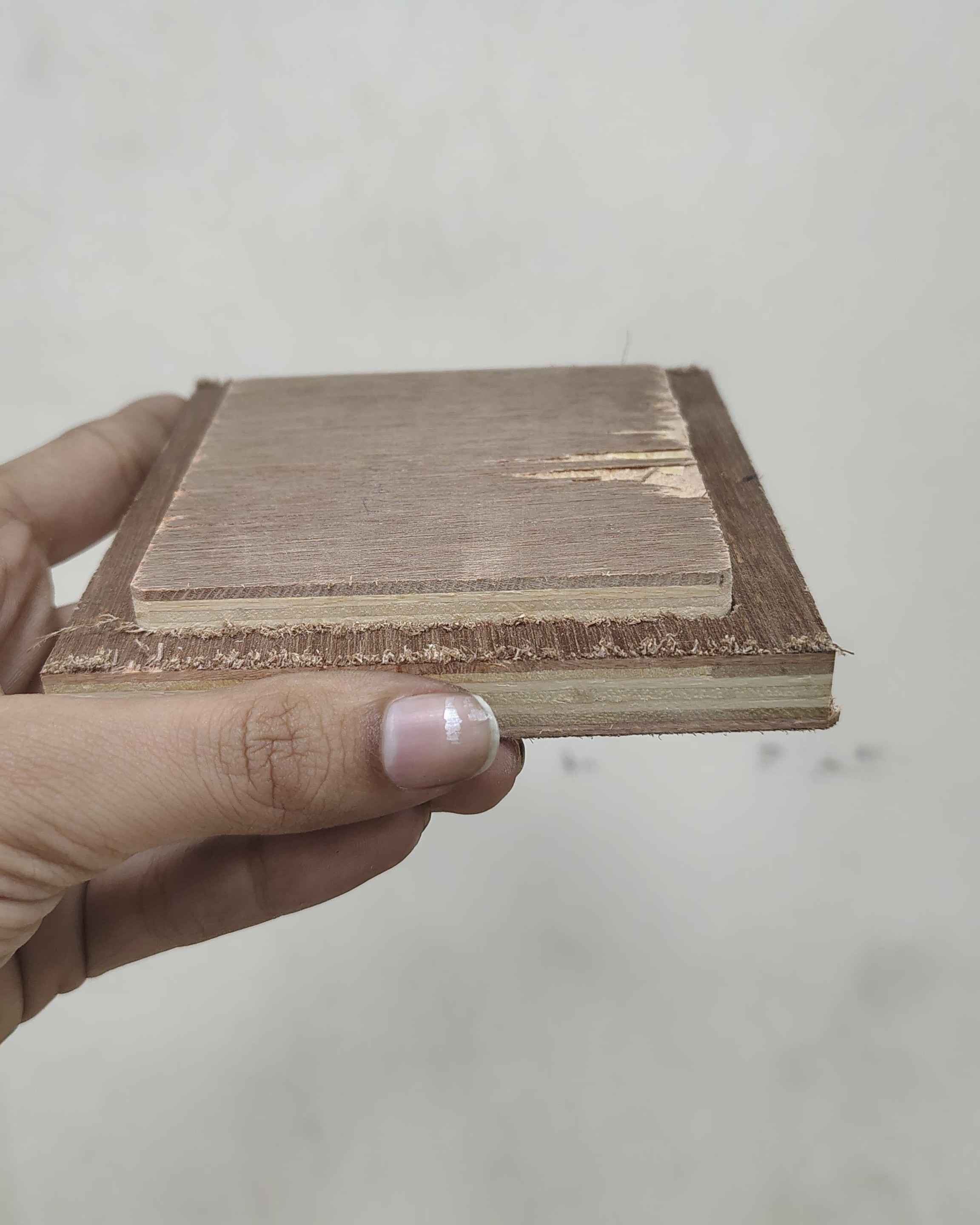
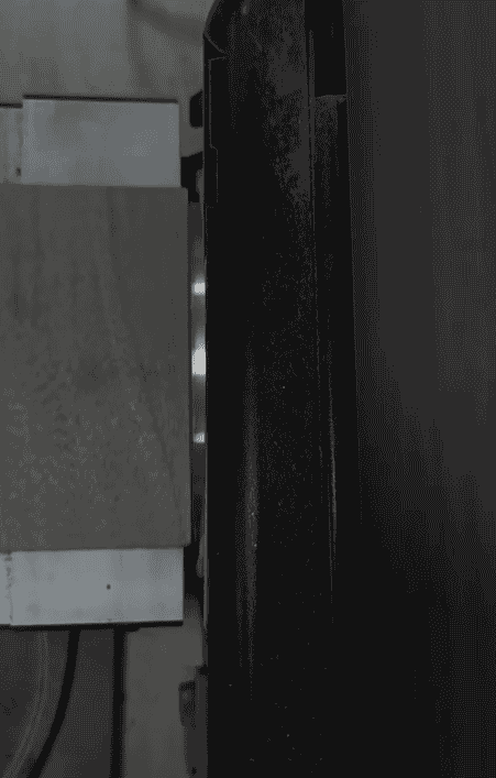
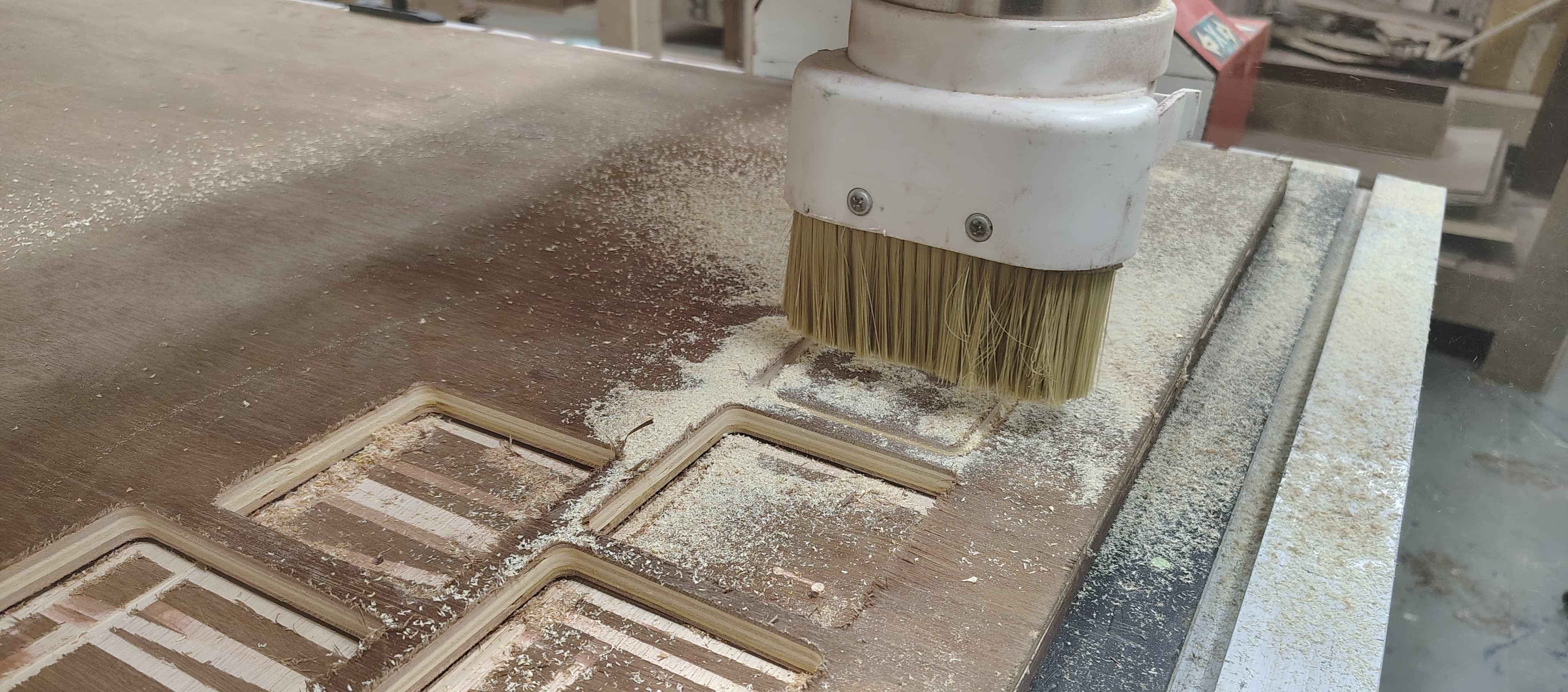
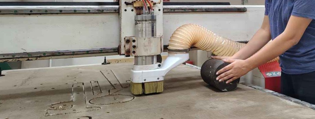
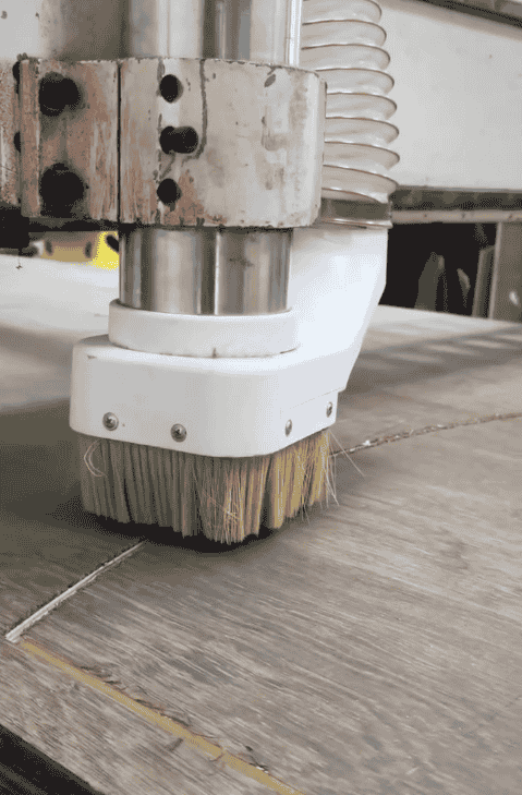
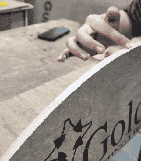
Image 2: The material, I used was 12mm ply, The ply was unfortunately buldged from the centre.
Thus, at point the bit out put stresses noise, thus I placed weights near the cutting bit area.
Milling, milling and milling.
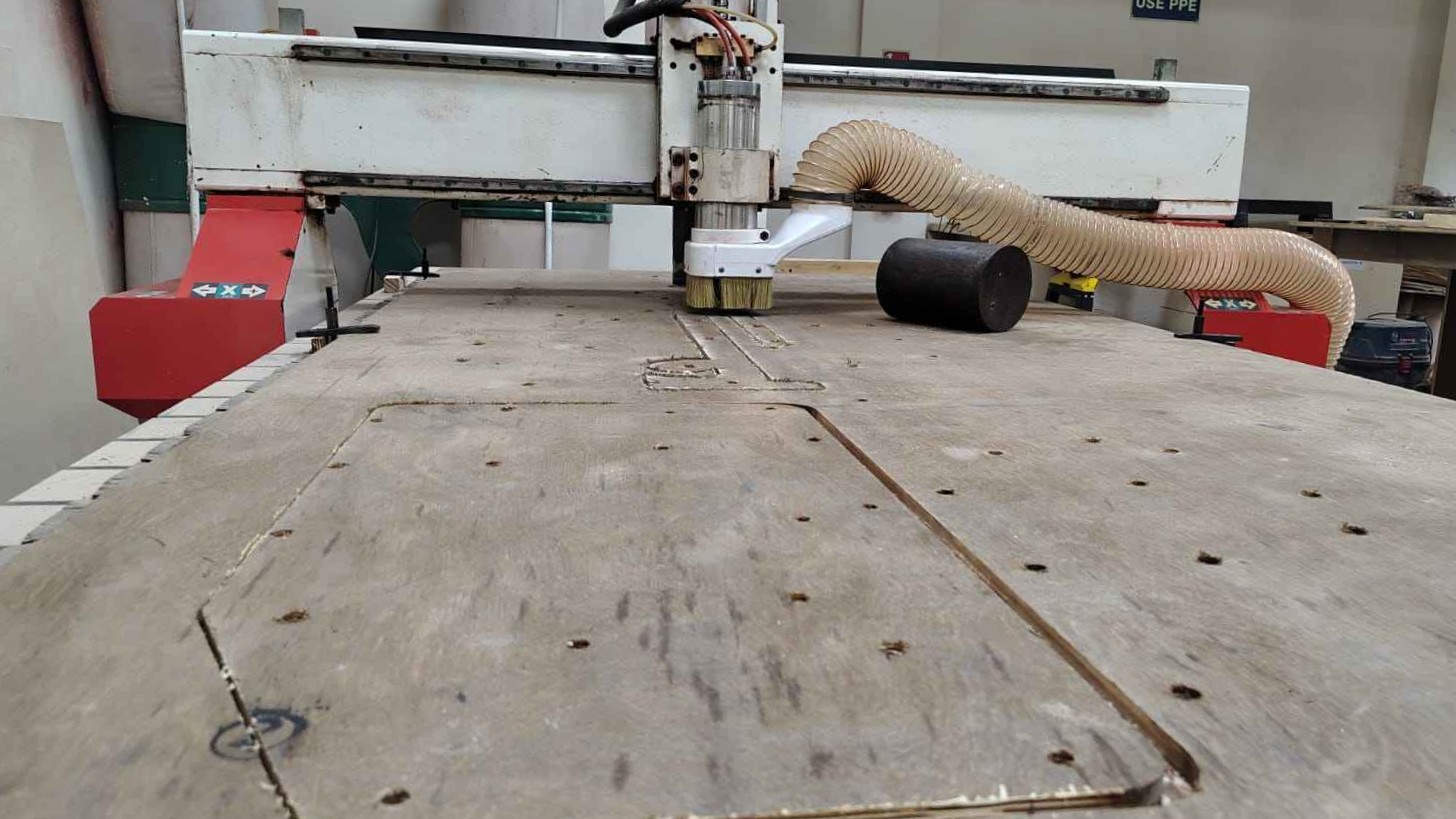
Weights to control buldge.
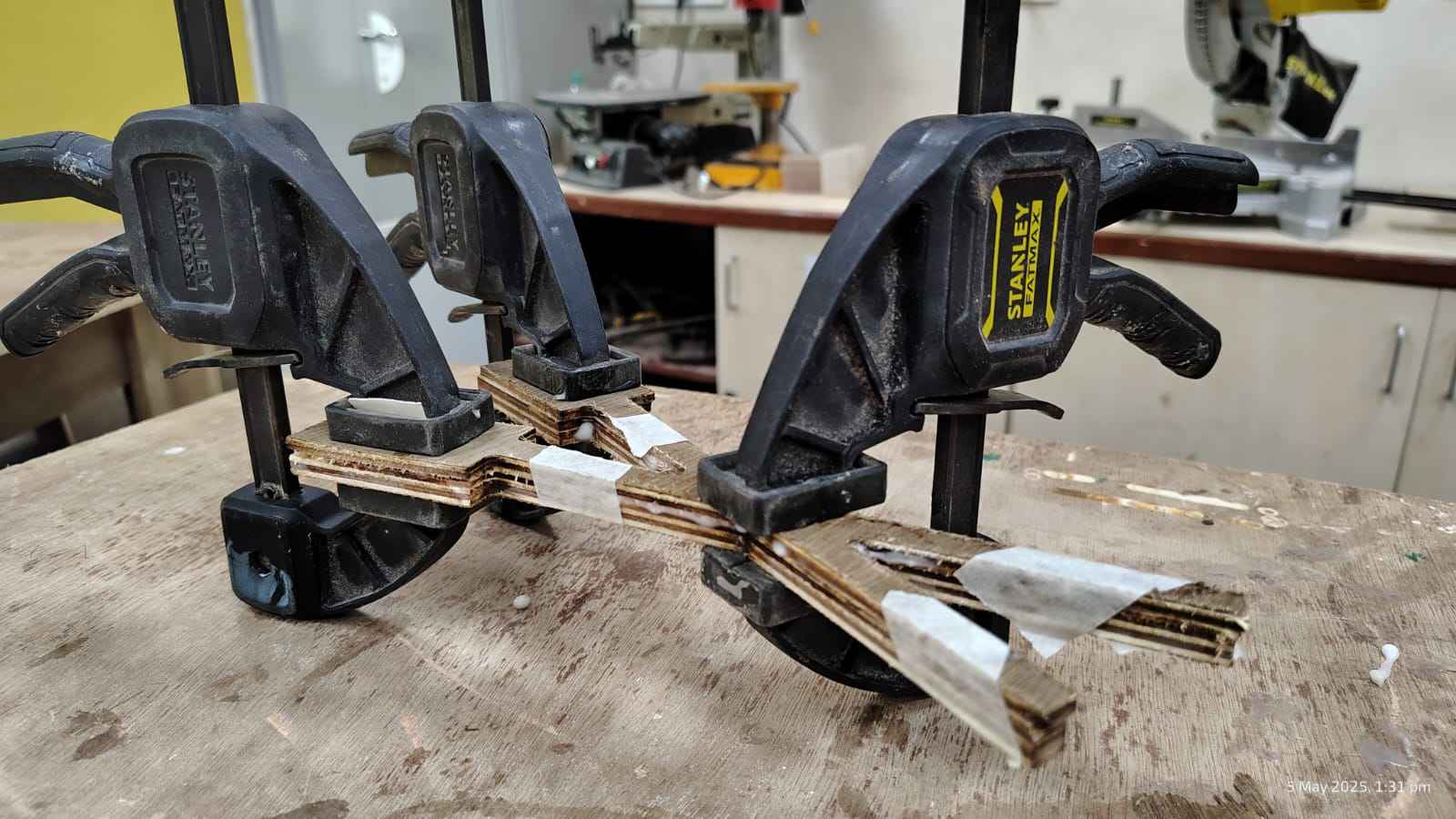
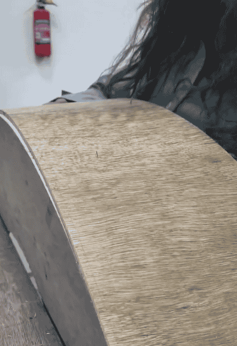
The material I chose, troubled me a lot. I learnt that Ply I used was a bit old.
As a material on storage led to withering of the glue that bind it.The same happened to one of the pieces
while cutting.
To which I had to later glue the layer which came off and I clamped the piece together for proper binding.
Cons of Ply material
6 HOURS LATER. Finally cut each piece.
Sanding of each piece
Checked dowel Precision.
Checked the assembly. Suprisingly, the dowel were a lot helpful for the positioning.
Dowels positioning helped me analyse the proper position of each piece of my model during assembly. The
assembly process was quite smooth.
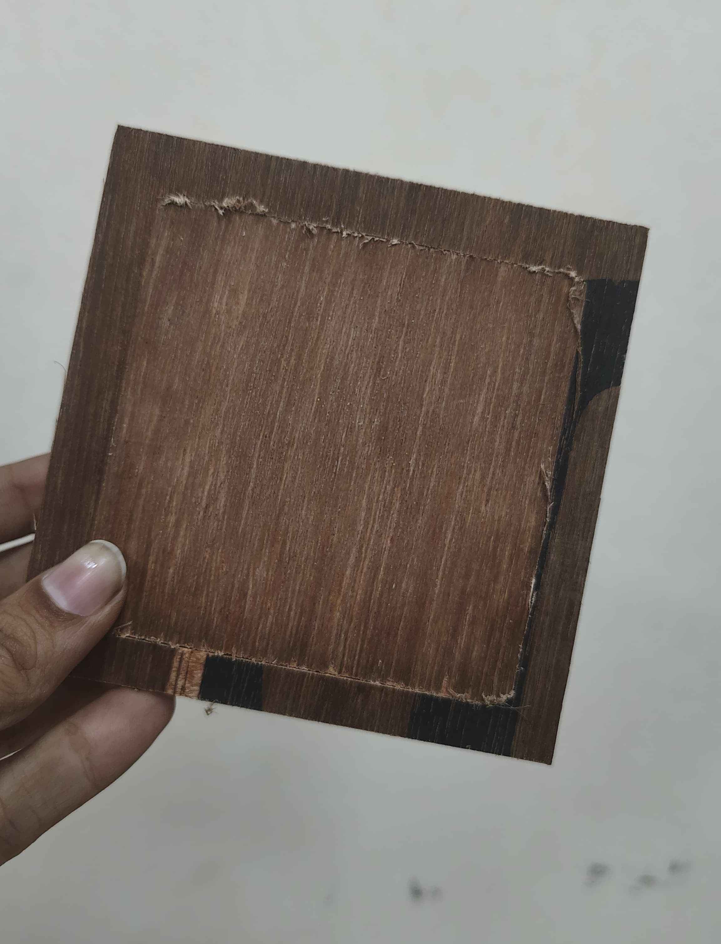
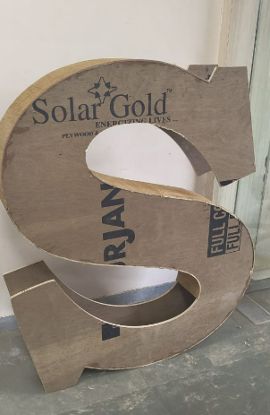
Another key learning from this process was the importance of correct ply placement on the CNC machine. If I
had placed the plywood upside down—with the opposite side facing up during cutting—the engraved alphabets
that are visible on the current surface wouldn’t have appeared. This highlighted how crucial it is to
carefully orient the material before CNC processing, especially when both sides have different finishes or
pre-existing marks. Proper placement ensures a clean final look and prevents unintended elements from
showing on the visible surface.
Post processing
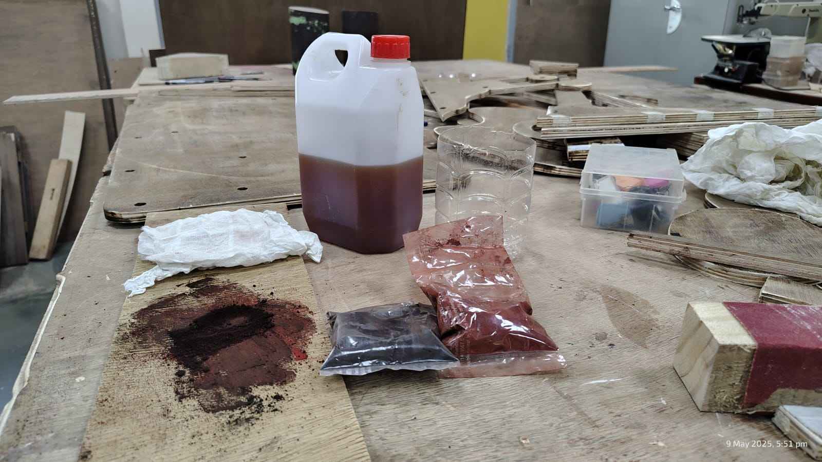
Material Used:
This is the set of materials I used for the wood staining process. It includes different colored pigment
powders- Mohagany, Sandalwood etc. for creating custom stain shades, a container of thinner for diluting the
stain or cleaning tools,
and a larger container containing the stain base called turpentine. I also used Asian Paints Touchwood
PU (Polyurethane) for the final protective coating to give the wood a smooth, durable finish. Sandpaper
sheets of varying grits were essential for preparing the wood surface before staining and for smoothing
between coats. Additionally, cloth pieces were used for applying the stain evenly across the wood surface.

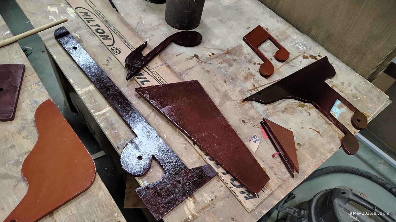
Mixing colour stains to form a mixture with addition of turpentine as stain base
Applying the coat with cloth
Sanding each stained pieces for a smooth texture
Applying touch wood for the final Finishing
Final Stain colour.
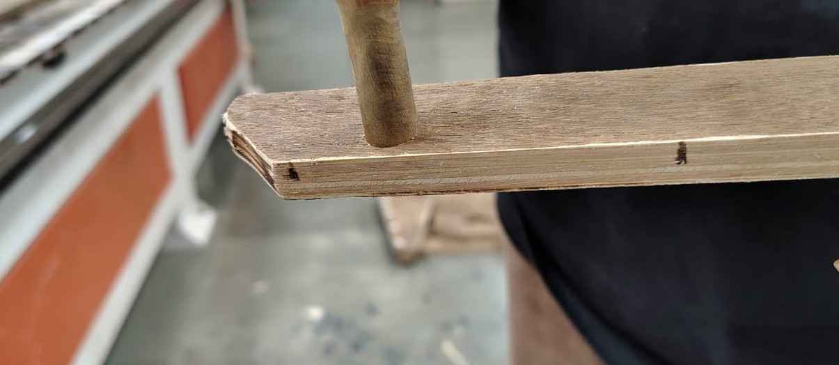
Fixing dowels in the pockets I created.
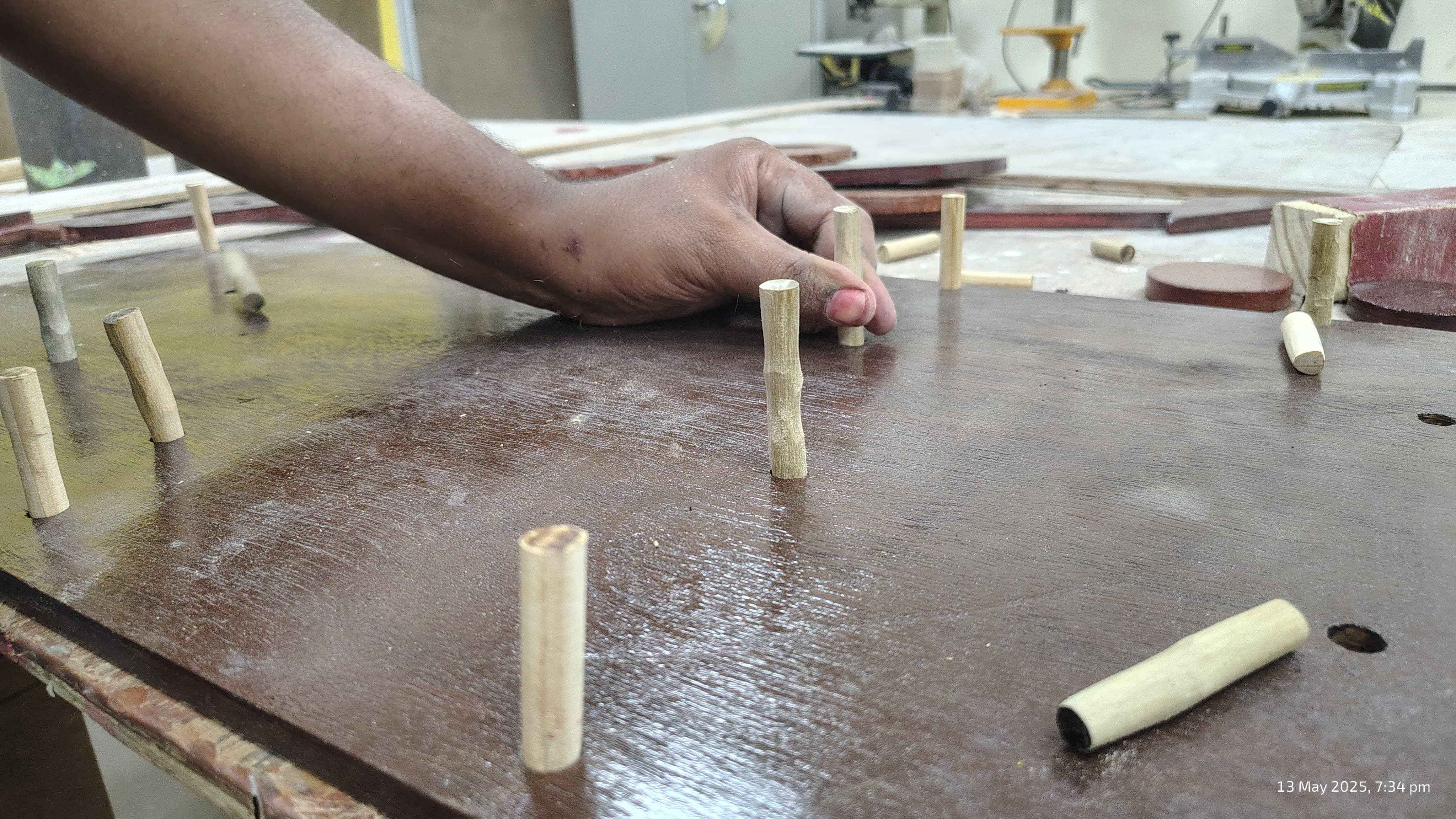
The pocket holes were a dimension of 12 mm, I bought a standard dowl size of 12 mm as well. From the
inference that
I derived from the group assignment, the tolerance is 0.2mm. For which I had to sand the dowels to a perfect
fit.
Learnings here were that I should have made the pocket size of 12.2 mm and added the dowls of 12mm as any
material sourced from
the market also comes in the stard sizes.
Fixed all the dowles and applied fevicol for strength.
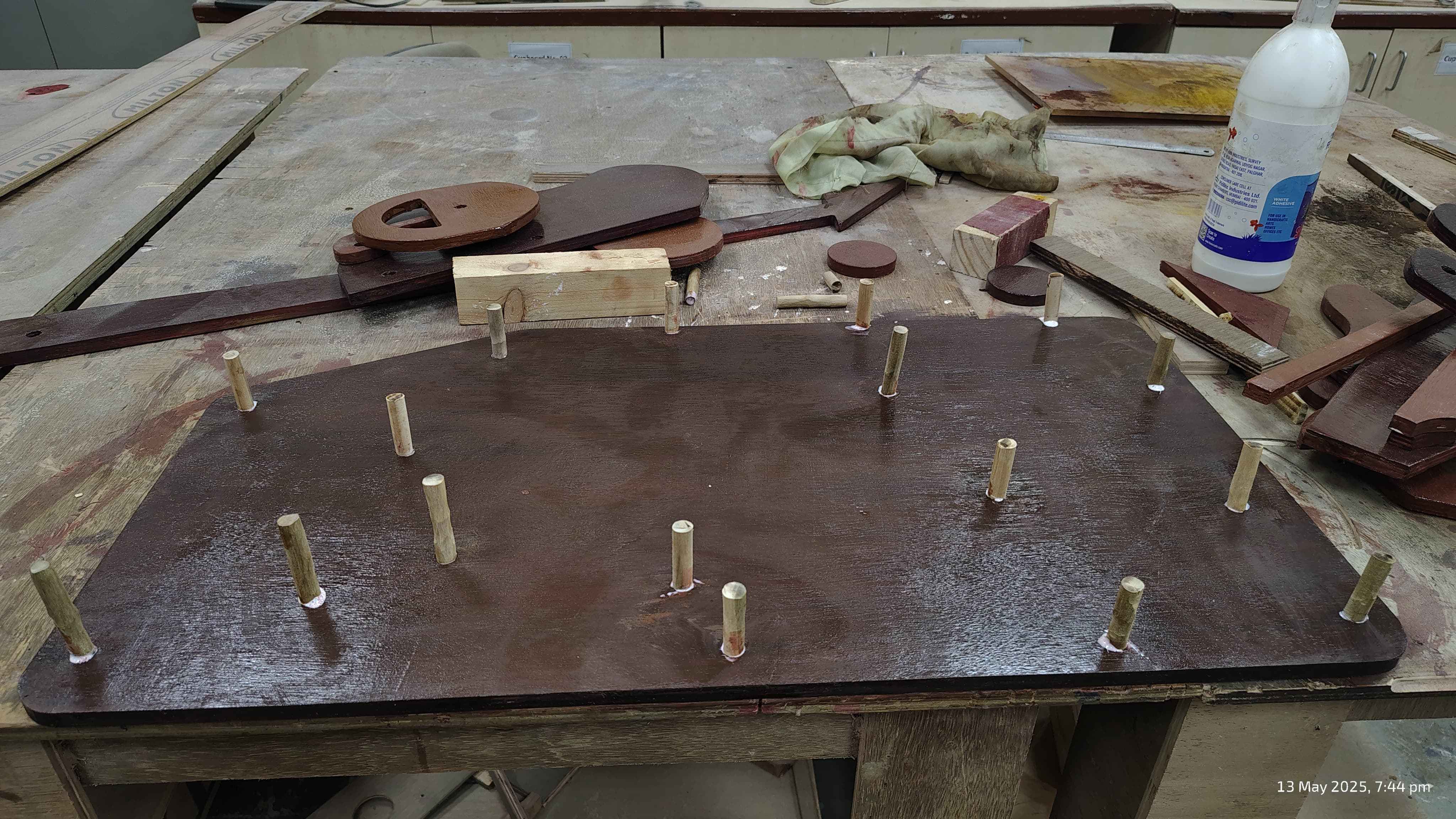
Adding up each layer. The friction fit from the dowels worked out perfectly.
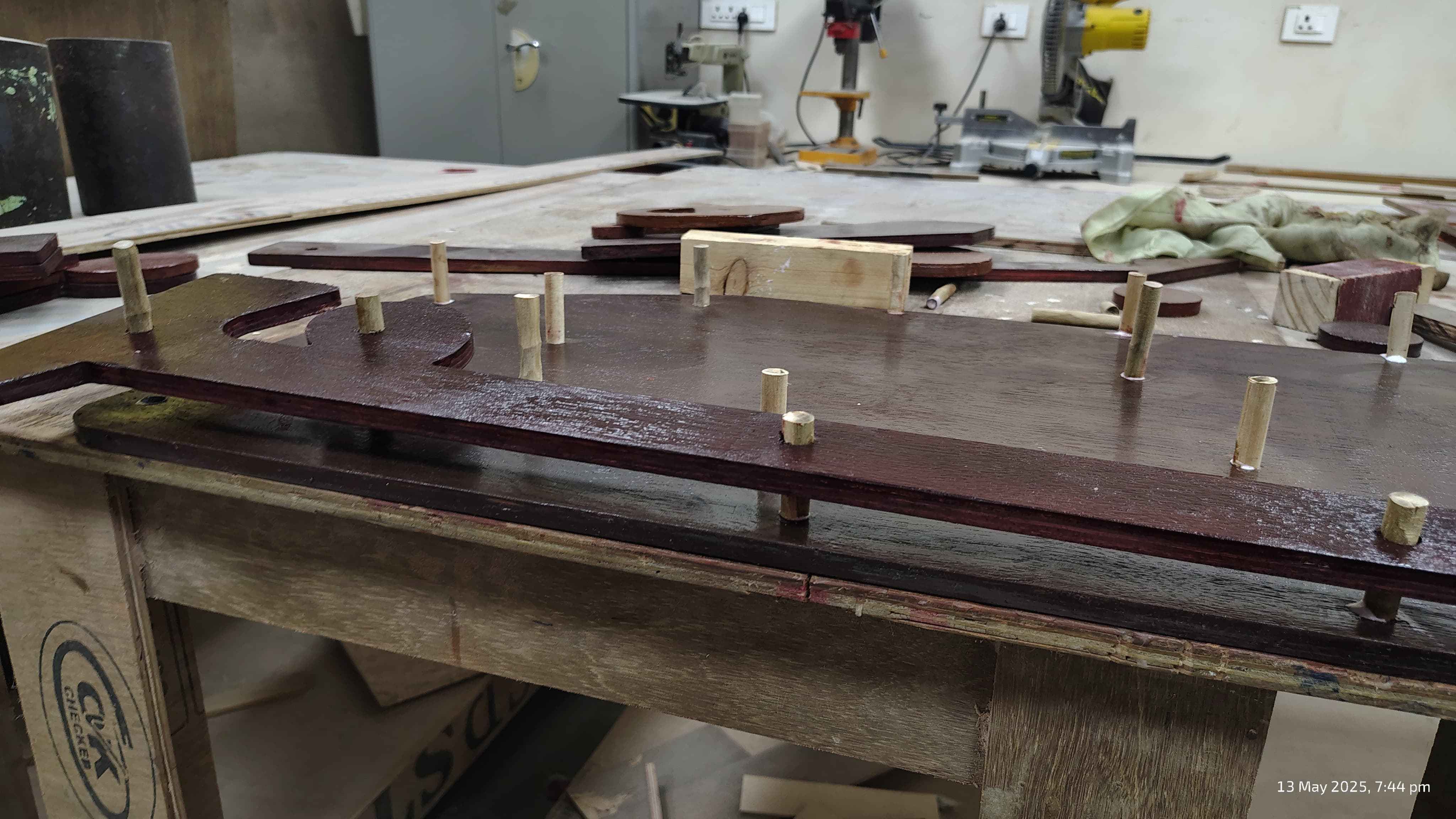
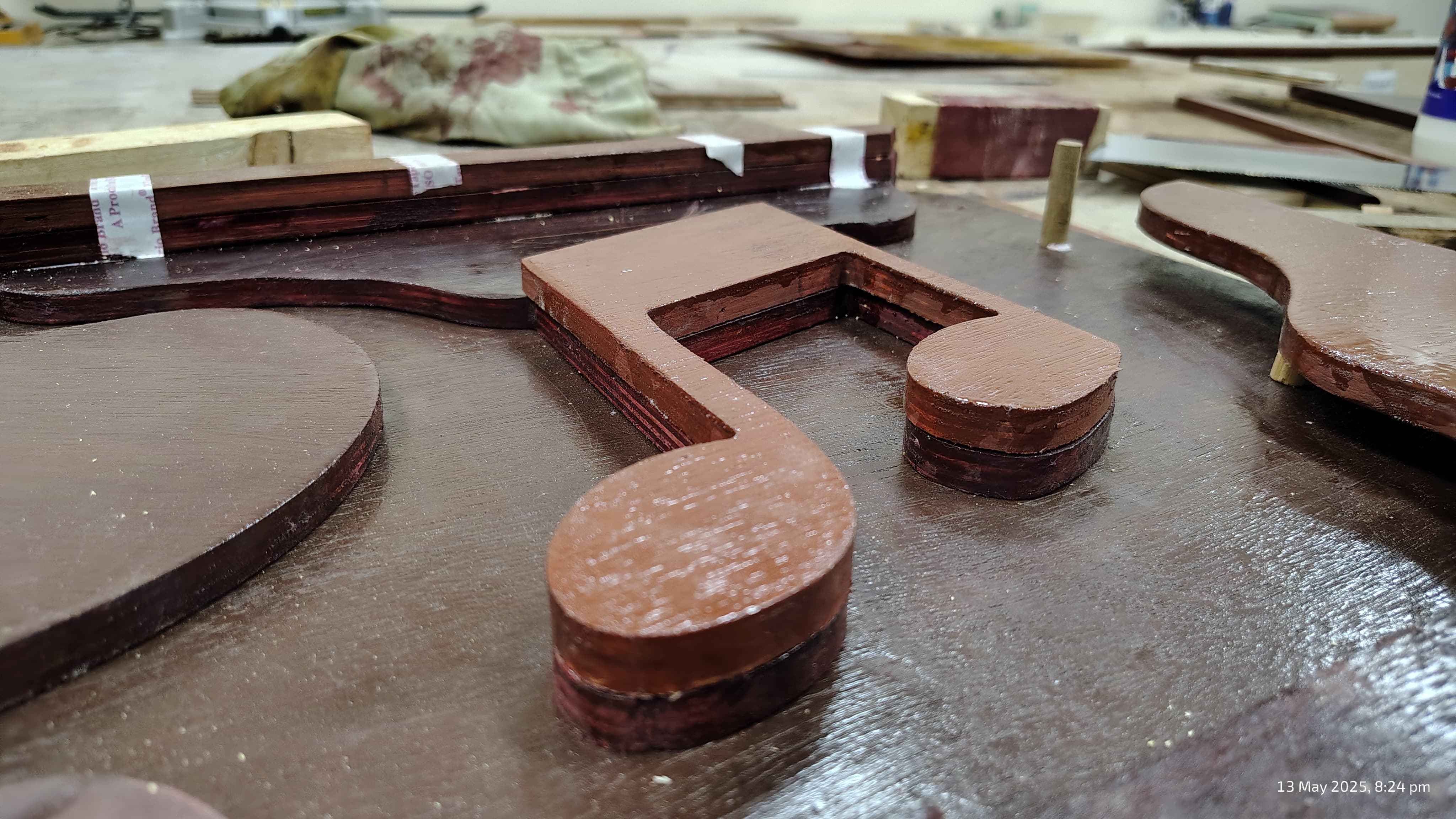
Before the top most layer I chop off the dowels to -6mm where the top piece fit perfectly.
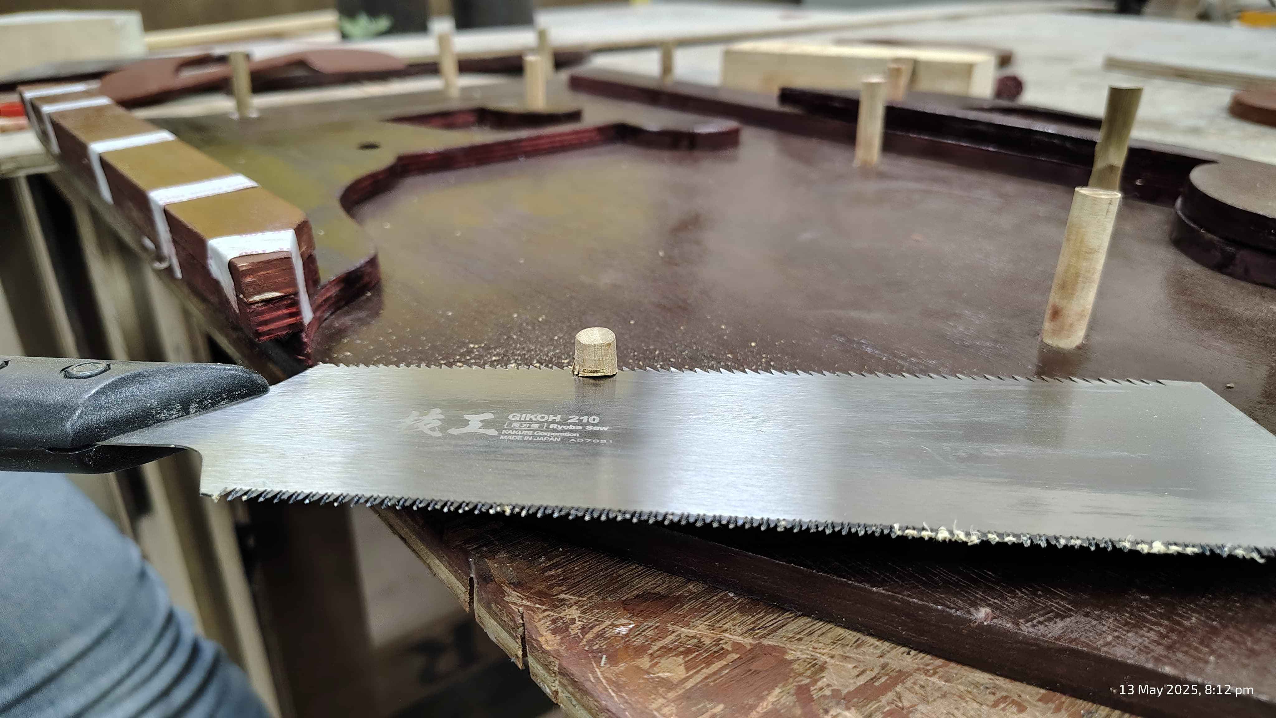
Achieved the idea to avoid any screws or dowel parts to be visible on the top surface. Also used
fevicol
at some places to give strength.
I am thankful to Riidl's
Lab Manager
Akhilesh
Sir,
to help me throughout the manufacturing process.
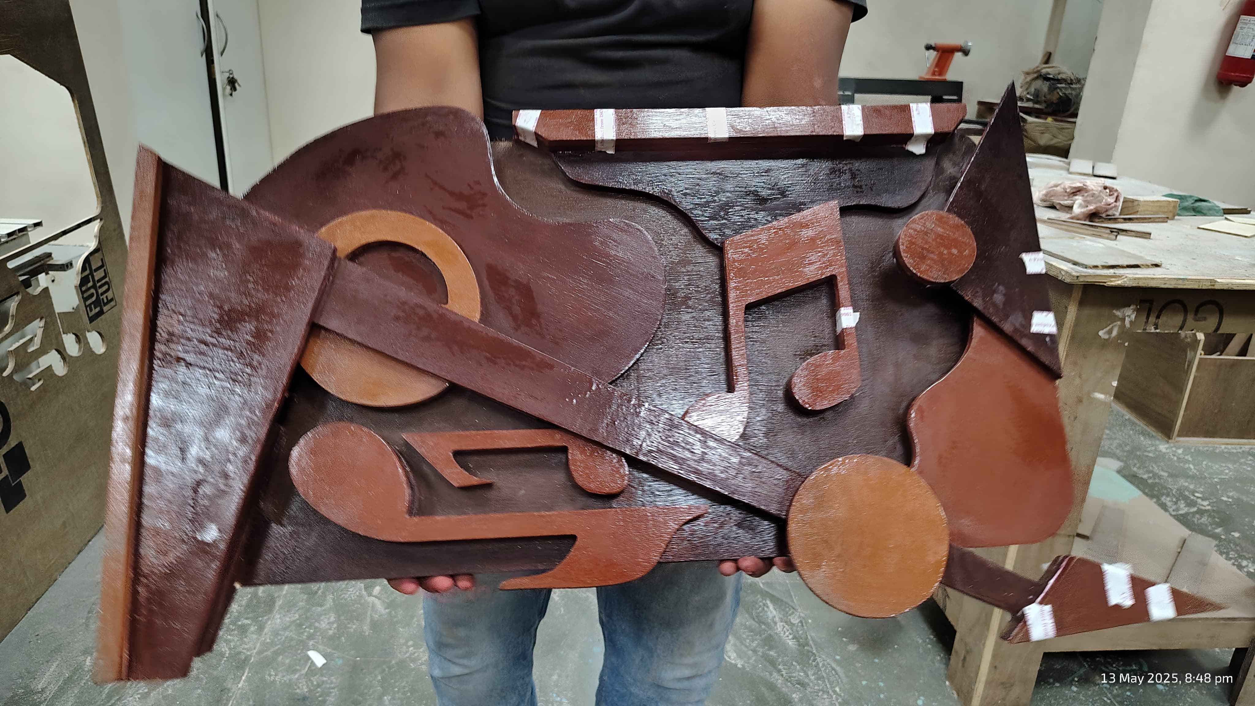
Finally the Final Product. Hero Shot
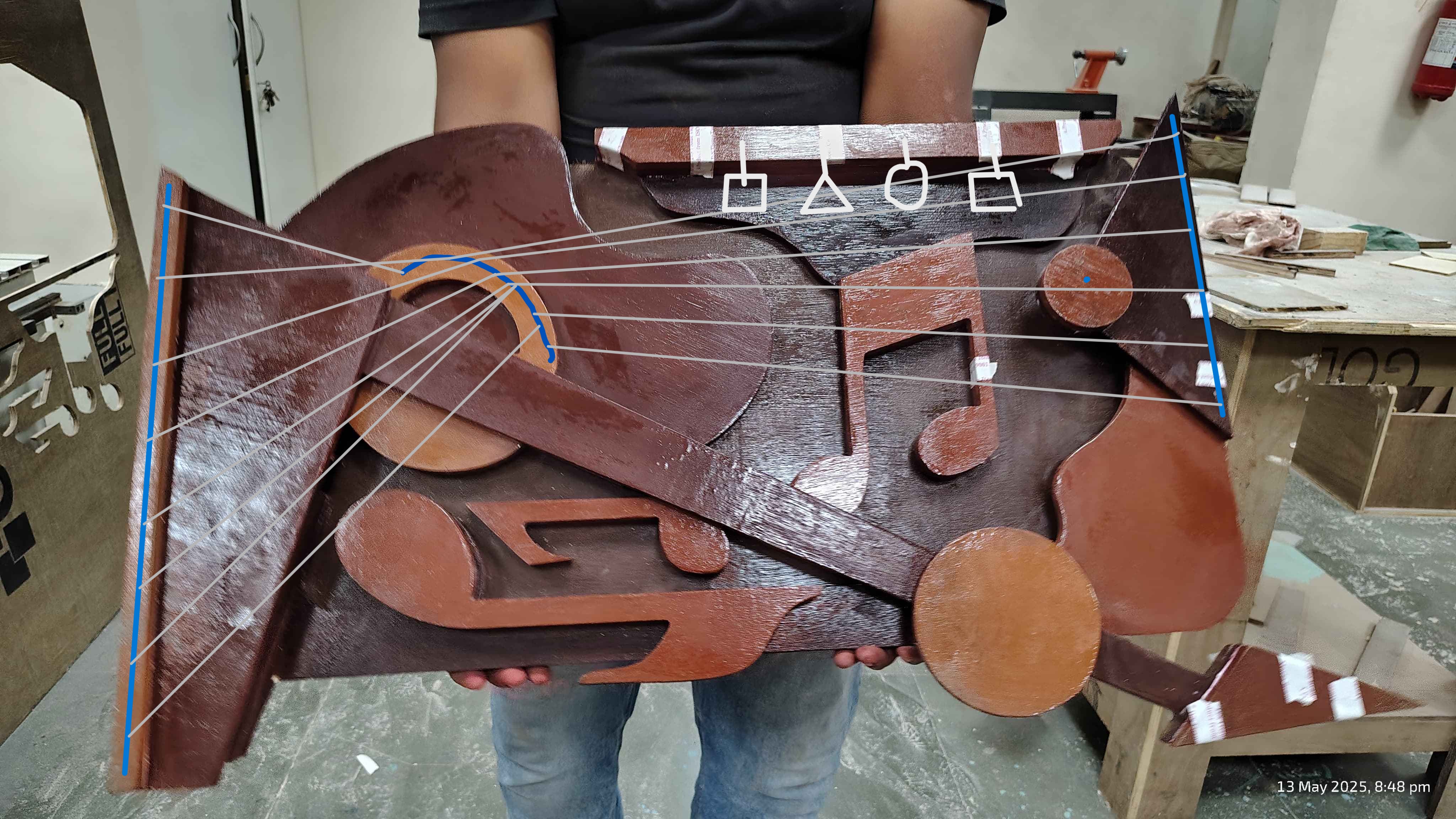
As a future aspiration, I aim to enhance the sensory and visual experience of the piece by integrating
strings
mounted on 3D-printed holders, creating both tension and interaction. Additionally, metallic shape hangings
will
be suspended from the top edge, introducing subtle movement and sound, making the artwork more immersive
Project file
Layer art Fusion Design file
Layer art DXF Design file
Layer art DXF Layout file 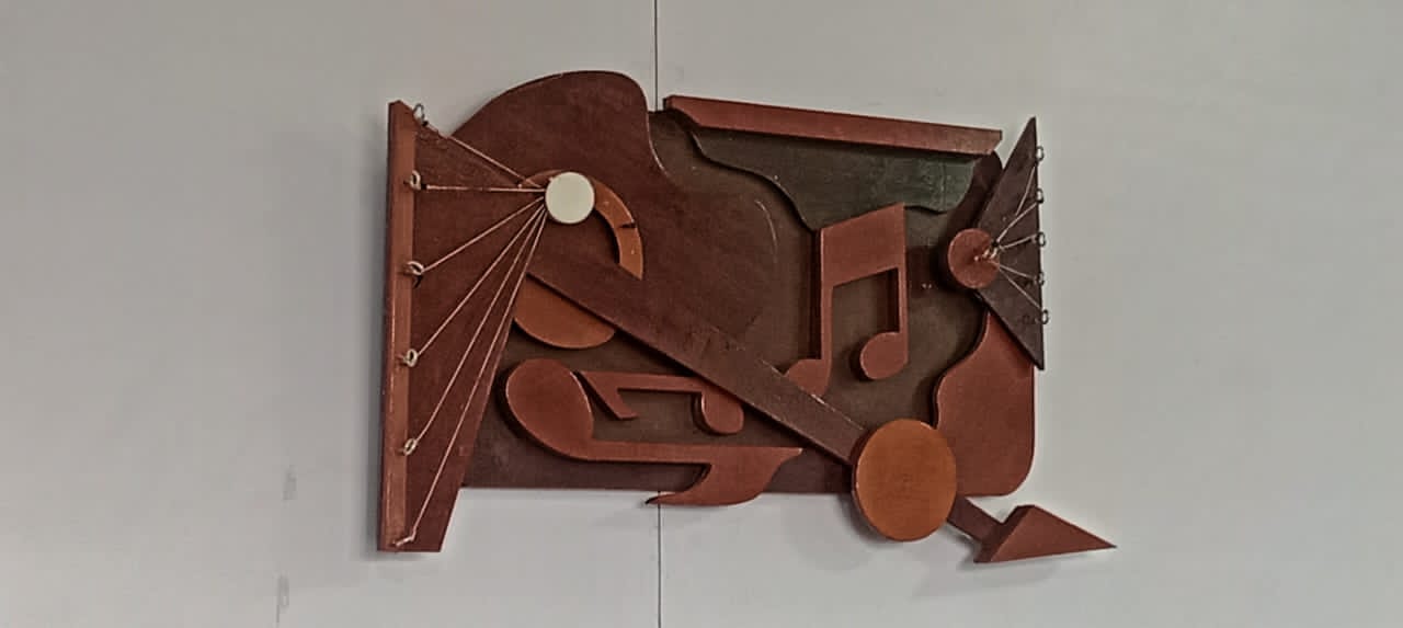


.png)