Assignment Brief:
- Understanding formats: Characterize your lasercutter's focus, power, speed, rate, kerf, joint clearance, and types.
- Laser cutting: Design, lasercut, and document a parametric construction kit, consideration of lasercutter kerf and assembly in multiple configurations.
- Vinyl cutter: Cut a design using the vinyl cutter and try to explore its process and application.
Understanding Formats:
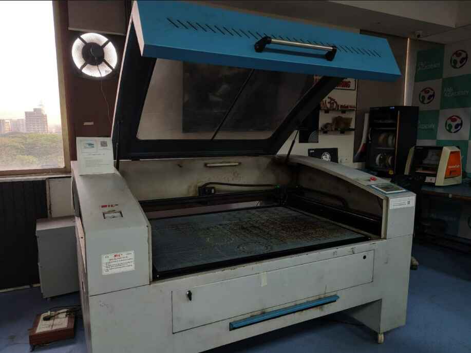
To begin with the fundamentals, the laser cutter I worked on and studied was from the Riidl FabLab lasercutter: CO2 Laser cutter from SIL (Suresh Indu Lasers Pvt. Ltd). Learn about the laser cutter Company: Suresh Indu Lasers For better understanding of lasercutter at Riidl- The Standard Operating Procedure (SOP) for Riidl lab as a pdf: Riidl Laser Cutter SOP (PDF)
CO2 Laser cutter from SIL (Suresh Indu Lasers).
Types of Laser cutter
A laser cutter is a machine that uses a high-powered laser beam to cut, engrave, or mark materials with
precision. The laser generates intense heat to vaporize, burn, or melt the material, creating clean and accurate
cuts.
Laser cutters come in different types based on the laser source they use. I reffered to ChatGPT to understand
The three main types of Laser cutters are:
-
CO₂ Laser Cutter:
- Best for: Cutting and engraving non-metal materials like wood, acrylic, paper, fabric, and leather.
- How it works: Uses a gas mixture (mainly carbon dioxide) excited by electricity between anode and cathode to produce a laser beam.
- Power range: 30W to 400W (common in commercial use).(In laser cutters, power (measured in watts, W) refers to the energy output of the laser beam. It determines how effectively the laser can cut or engrave materials.)
- Pros: Affordable, high precision, works well on organic materials.
- Cons: Not effective for cutting most metals without additional modifications.
-
Fiber Laser Cutter:
- Best for: Cutting and engraving metals (steel, aluminum, brass, copper) and some plastics.
- How it works: Uses a fiber-optic cable to amplify light, creating a powerful and concentrated laser beam.
- Power range: 500W to 12,000W (industrial applications).
- Pros: High efficiency, long lifespan, minimal maintenance.
- Cons: More expensive than CO₂ lasers, not ideal for organic materials.
-
Diode Laser Cutter:
- Best for: Engraving on wood, plastics, leather, and some metals (with coatings).
- How it works: Uses semiconductor diodes to generate a laser beam.
- Power range: 1W to 15W (for hobbyists and low-power applications).
- Pros: Compact, affordable, energy-efficient.
- Cons: Low power, slow cutting speed, limited material compatibility.
Laser Cutter Safety Measures
Laser cutting safety measures prevent accidents, protect users, and ensure efficient operation. Proper ventilation removes toxic fumes, reducing health risks. PPE, like UV safety glasses and fitted clothing, shields against burns and laser exposure. Correct material handling and laser settings prevent hazardous emissions and overheating. Fire safety and workspace organization minimize risks, ensuring precision and smooth workflow.
- Ventilation: Ensure proper airflow or use an exhaust system to remove fumes.
- Material Handling: Check MSDS; avoid hazardous materials like PVC.
- Settings: Adjust power, speed, and focus for clean cuts and safety.
- Fire Safety: Keep a fire extinguisher nearby; never leave unattended.
- Workspace: Keep the area clutter-free; close the enclosure and clean waste regularly.
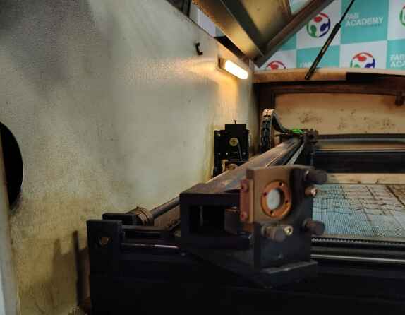
Laser cutter Working
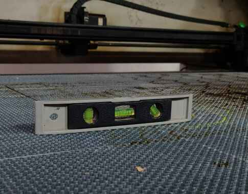
At the rear, a CO₂-filled glass tube generates a laser beam when electrified. The beam travels via mirrors to the cutting head, where a lens focuses it for precise cutting and engraving. The key Components of the Lazer cutter are: 1. Cooling System: Circulates water around the tube to prevent overheating. 2. Exhaust System: Uses a fan to remove smoke and fumes, ensuring ventilation. 3. Laser Bed (3 × 4 ft): Holds materials; must be level for accuracy, checked using a spirit level.
- Vinyl: A flexible, adhesive-backed material used for signage, stickers, and labels. Example: Wall decals, laptop stickers.
- Outdoor Vinyl Weather-resistant vinyl designed for long-term outdoor use, often UV-resistant and waterproof. Example: Storefront signage, car decals, outdoor banners.
- Clear Film: Transparent vinyl used for overlays, window decals, and see-through stickers. Example: Glass door branding, clear labels on bottles.
- Reflective Film: Contains tiny glass beads or prisms that reflect light, making it highly visible at night. Example: Road signs, emergency vehicle decals.
- Fluorescent Vinyl: Bright, neon-colored vinyl that enhances visibility, especially in low light. Example: Safety signage, high-visibility stickers.
- Car Film: Specialized vinyl used for vehicle wrapping, available in glossy, matte, or textured finishes. Example: Full-body car wraps, racing stripes, paint protection film.
- Thick Substrate: Rigid or thick materials that require higher cutting force, such as magnet sheets or PVC. Example: Industrial labels, thick stencil sheets, rigid signage.
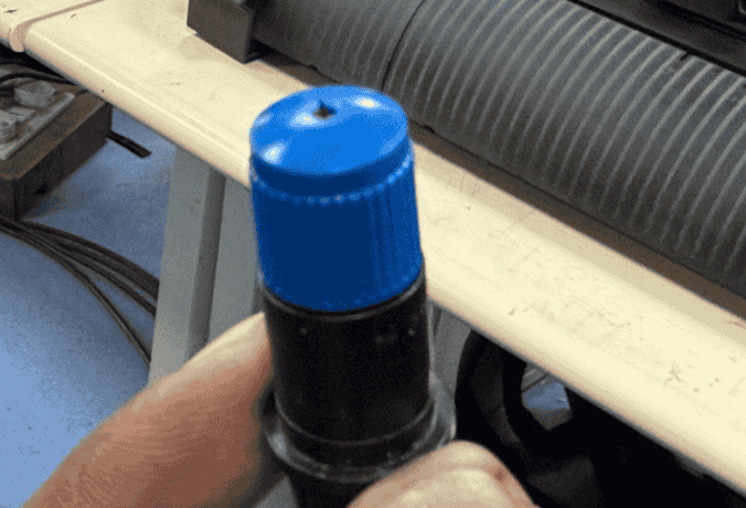
- Adjusting the Blade: Begin by properly setting up the knife (blade) of the vinyl cutter and adjust the knife tool screw as needed to ensure the blade protrudes just enough to cut through the vinyl without damaging the backing layer.
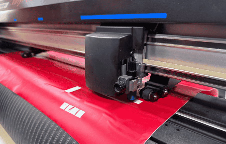
- Loading the Vinyl Sheet: Manually insert the vinyl sheet into the machine, ensuring it is fed in straight. Flatten the material to remove any wrinkles or air bubbles that could affect cutting precision.
- Aligning the Material & Stopper: Position the vinyl under the machine’s rollers and align it with the blue guides above. Adjust the stoppers (grit rollers) to securely hold the vinyl in place while allowing smooth movement.
- Locking the Handle: Once aligned, lock the handle to secure the material in place. This step prevents any shifting during the cutting process, ensuring accuracy.
- Initiating the Cutting Process: Start the machine, allowing it to perform an initial pass where the paper roll moves back and forth without cutting. This helps the machine estimate the total material size. After this check, the cutter will automatically pull the material back and begin the actual cutting process.
- Safety Precautions: Keep hands and fingers away from the moving parts while the machine is running. Avoid making sudden adjustments or touching the material mid-process to prevent misalignment.
-
Step 1: Install and Launch Graphtec Studio 2 from
here
- Download the software from the official Graphtec website.
- Run the installer and follow on-screen instructions to complete the installation.
- Open Graphtec Studio 2 after installation.
-
step 2: Create or Import a Design.
-
Import an Existing File:
The linked I reffered to witch house

Click “File” > “Open”. Here I opened an already existng vector to image trace.
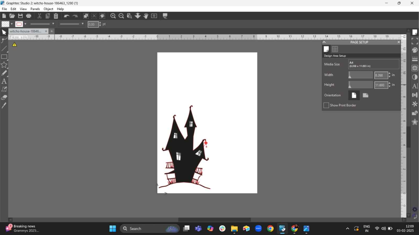
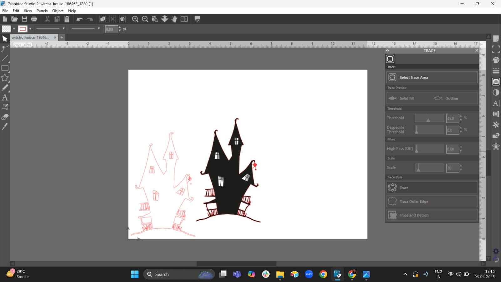
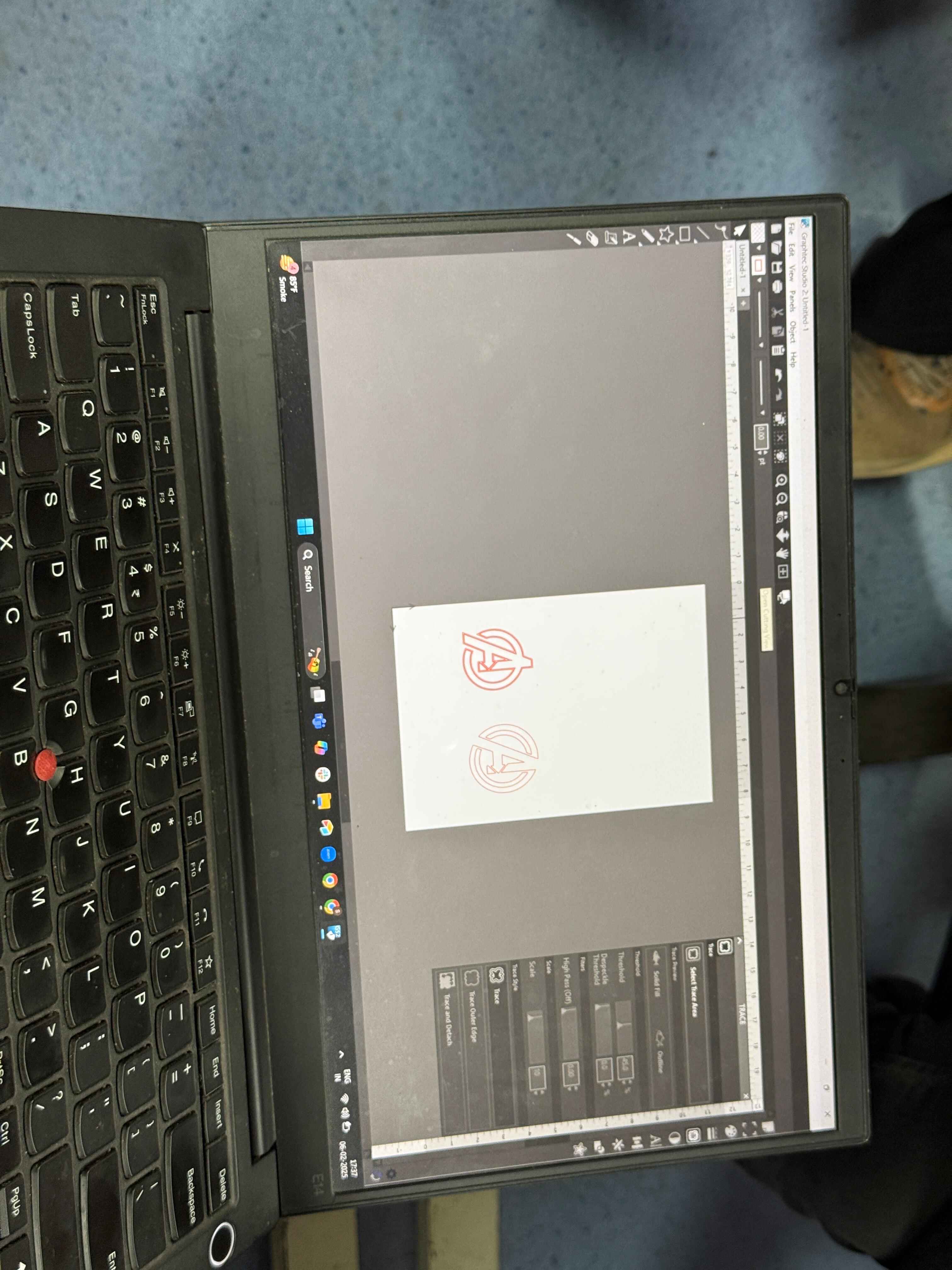
- Step 3: Trace The image.
Trace the image with the trace tool:
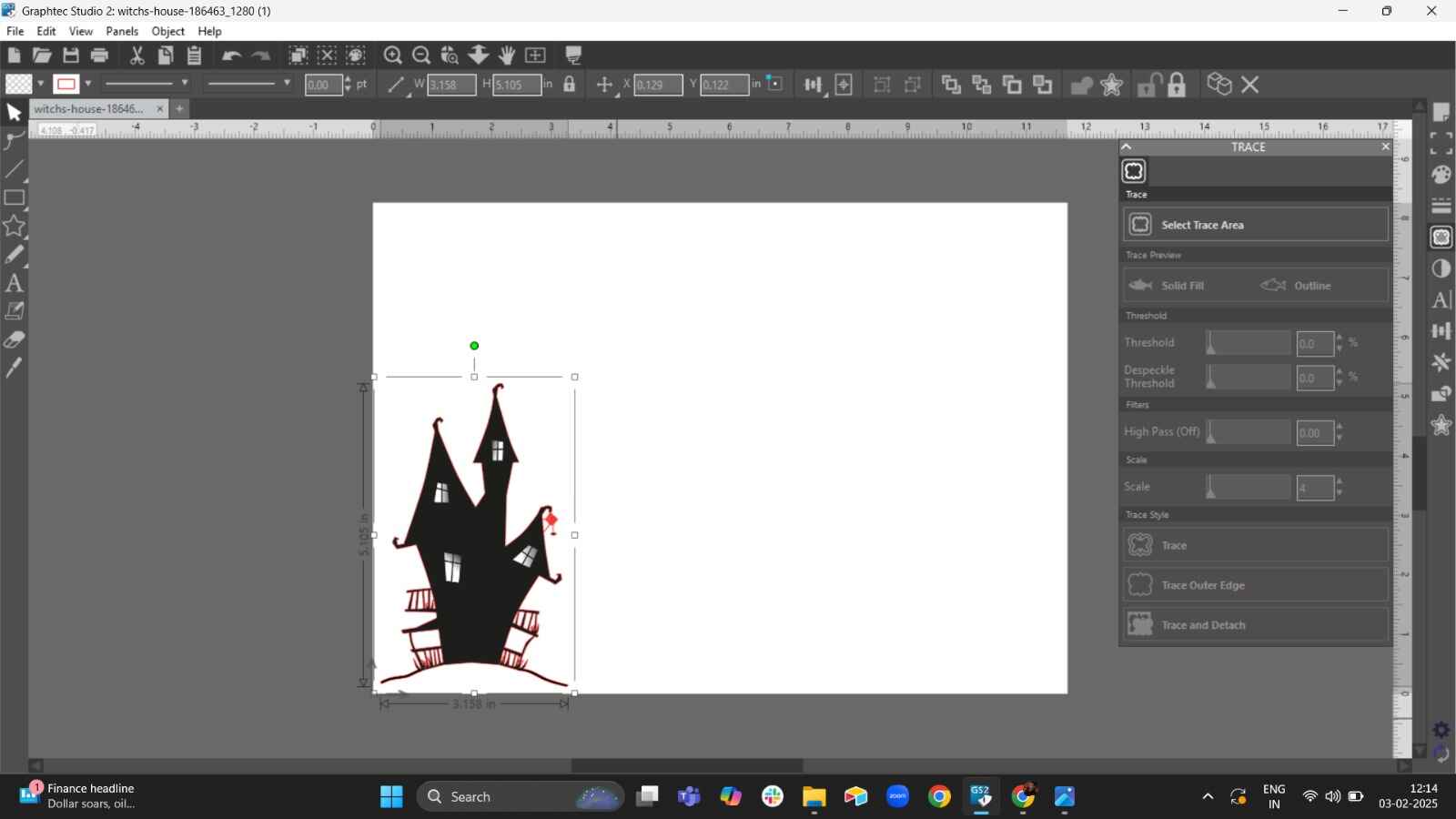
Select the area type:
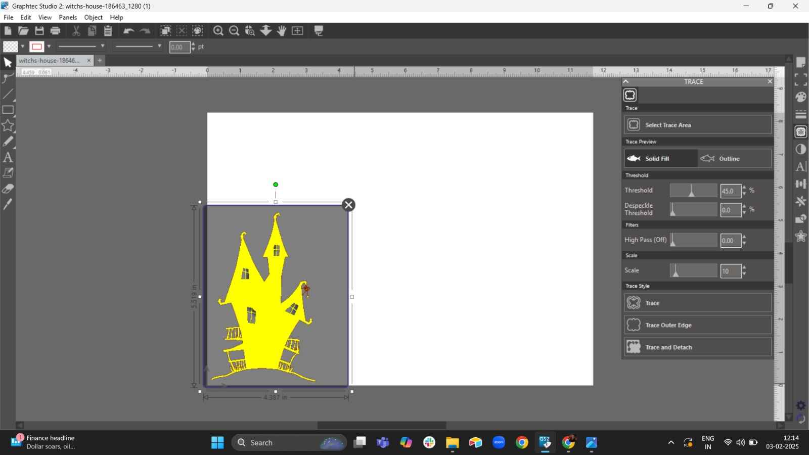
-
Delete the actual image after forming the traced image:
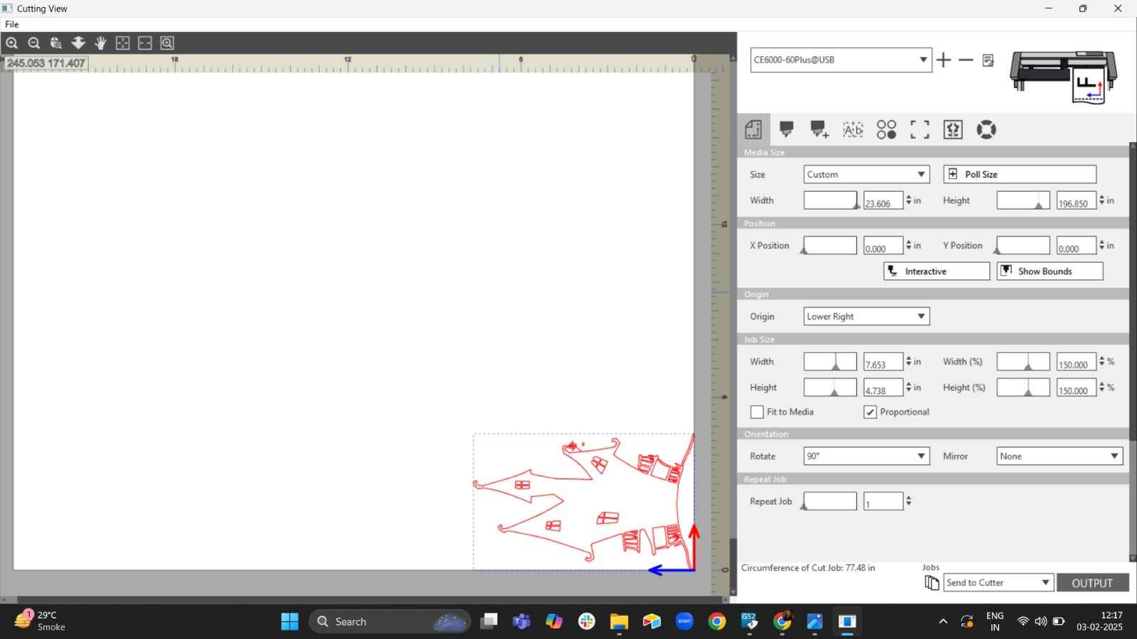
Click “Send” to transfer the design to your Graphtec cutter:
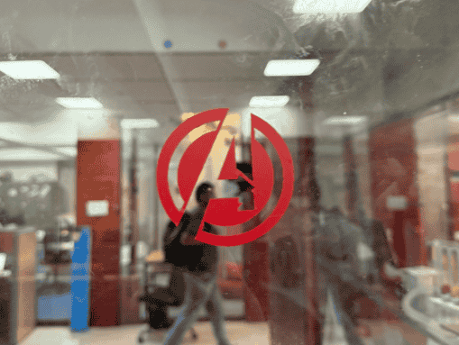
Final Outcome: Avenger logo
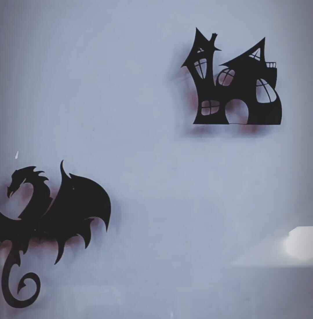
Final Outcome: Witch House
Kirigami
Inpiration form

- 1. Taking Inspiration from the above art work of Paul cocksedge I devised a concept
and decide on the design – in this case, a parametric wave-like pattern.
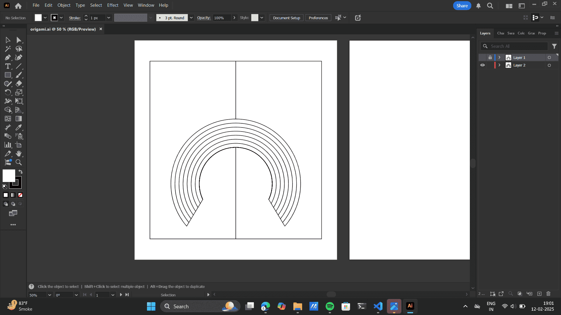
I used Adobe Illustrator and then Graphtec Studio 2, to create a vector file (DXF or SVG). Further I
ensure the design consists of precise curved cuts that will lift off the base material in a controlled manner.
Design on Illustrator
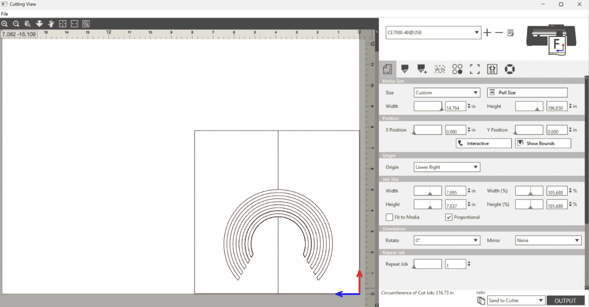
Import to Graphtec studio 2
- 2. Material Selection
I Chose a thin sheet of cardstock for better flexibility.
Ensured that the material is compatible with the Graphtec Vinyl Cutter.
- 3. Setting Up the Vinyl Cutter
Loaded the material onto the Graphtec CE7000 vinyl cutter.
Aligned it properly with the blue stopper guides to avoid misalignment.
Locked the handle to keep the material steady during the cut.
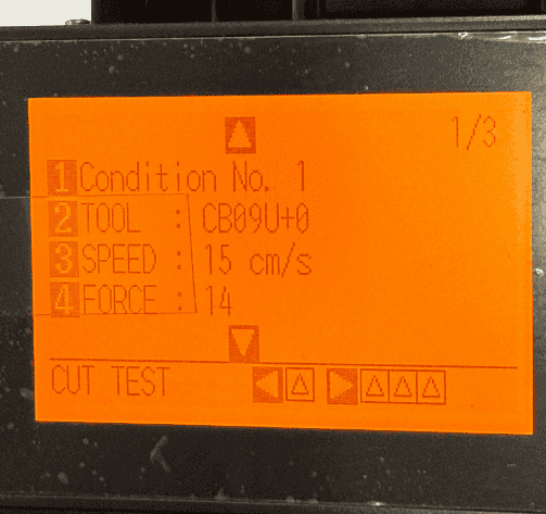
- 4. Adjusting Cutter Settings
Blade Depth: Adjusted the blade just enough to cut through the top layer but not completely detach the shapes to
create a pop-up effect.
Cutting Force: Moderated force to ensure clean cuts without tearing.
Speed: A lower speed ensures more precision for intricate designs.
- 5. Cutting Process
Sent the file to the cutter from Graphtec Studio 2.
The cutter performs an initial pass to estimate material size before executing the actual cuts.
The machine follows the vector paths, cutting the material accordingly.
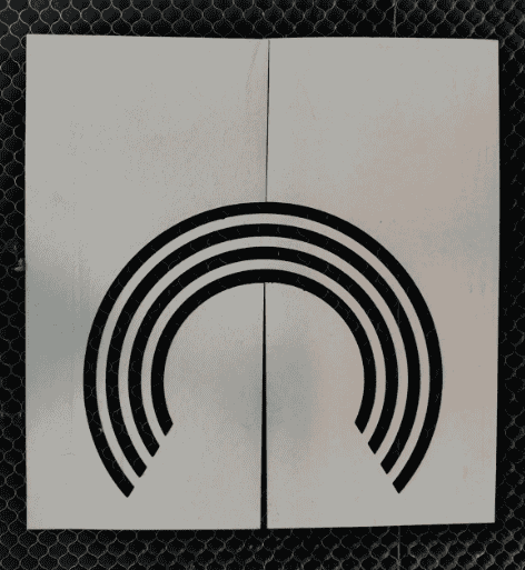
Vinyl cut
Folding alternately in opposite direction.

Folding and restoring
- 6. Post-Cutting Handling
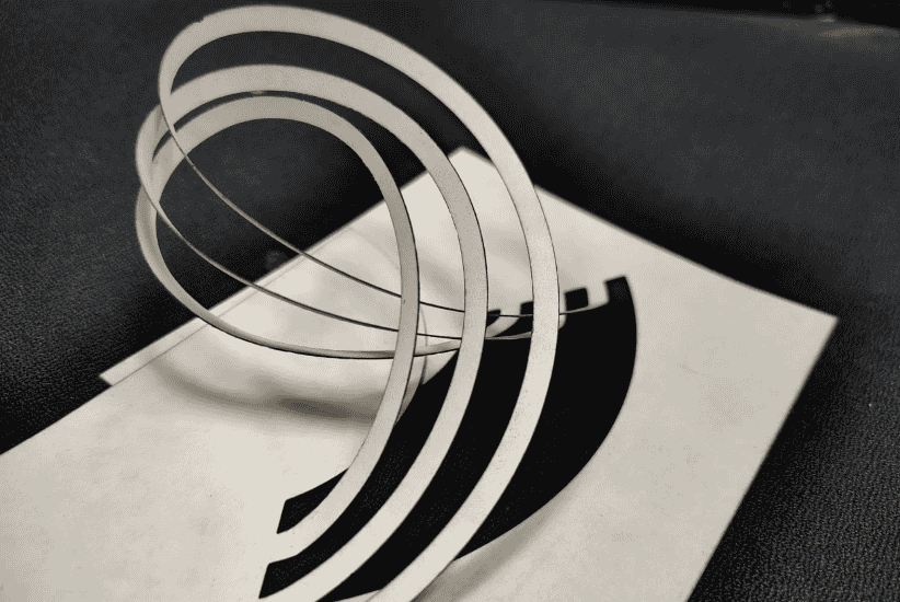
Carefully lifted the curved sections without detaching them completely.
Gently push the cut segments upwards to create the 3D wave effect seen in the image.
Ensure the curves hold their shape without breaking.
- 7. Final Adjustments & Presentation
Cleaned up any excess material or unwanted cuts. Folding the kirigami folds was an very inticate task here. I
made a folding error in the first model and finally built the final model.
Photographed the model with proper lighting to highlight its shadow effects and depth.
Kirigami Final Outcome: Hero shot
.png)
Following the same steos used for witch house cutting. I made the kirigami cut with smoothness. The kirigami output on Vinyl printing was very efficient as unlike laser cutter the vinyl cutter doesnt burn the loaded material.
Vinyl Sticker
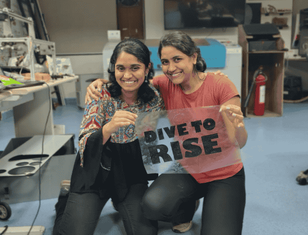
I wanted to explore how vinyl could be used on textiles, so my friend Sharvari and I decided to transfer our cut design onto a T-shirt. We chose Akhilesh Sir's favorite quote, Dive to Rise, and got to work.
Designing in Graphtec Studio 2
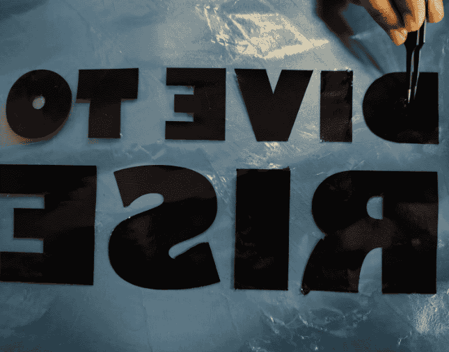
Instead of using external software, we thought of design out quote layout directly on Graphtec Studio 2. We experimented with different fonts, testing both thick and thin strokes to see how they would appear on fabric. To refine the design, we used the group and ungroup functions to adjust letter spacing and alignment..png) Once satisfied, we exported the file and sent it to the cutter. The vinyl was cut just as we did
previously. We first transferred it onto
a transparent sheet to keep the design intact.
Later we pulled of the excess vinyl from the sheet, keeping the quote type in place.
Once satisfied, we exported the file and sent it to the cutter. The vinyl was cut just as we did
previously. We first transferred it onto
a transparent sheet to keep the design intact.
Later we pulled of the excess vinyl from the sheet, keeping the quote type in place.
Sharvari and myself holding the transfer sheet with the cut vinyl design "DIVE TO RISE". This sheet was used to remove the design from the vinyl roll and prepare it for application onto fabric.
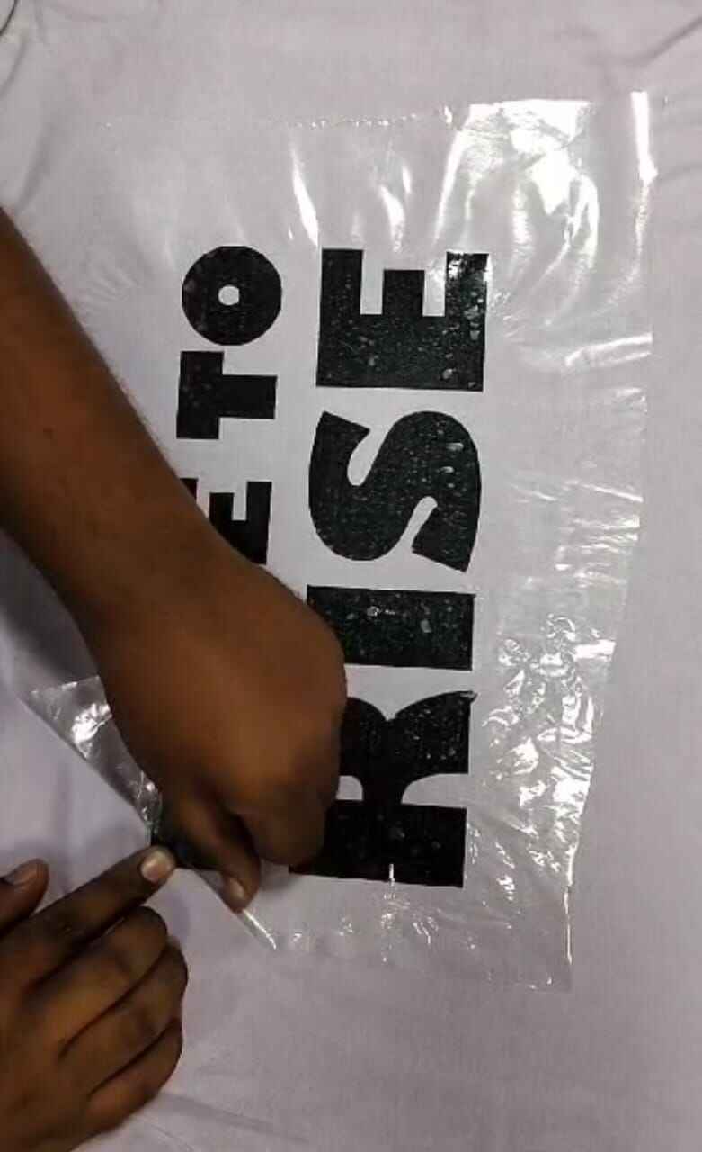
Applying the transfer sheet with the quote onto a T-shirt. Carefully peeling off the sheet to ensure the vinyl adheres properly to the fabric.
 FInal Outcome : Hero shot

In the image my Fab Mentor Pranav Gawde and professor Akhilesh Zambre
Metal Engraving
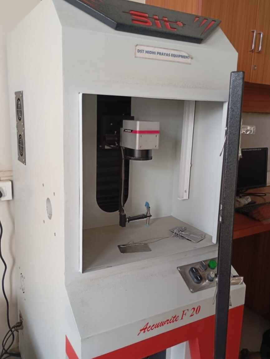
Fibre Laser Marking
A fiber laser marking machine is a type of laser engraving or marking system that uses a fiber laser source to create high-contrast, permanent marks on various materials. It is widely used in industries for marking metals, plastics, and other materials due to its precision, speed, and durability. Riidl Metal Engrave SOP. You can get the details of types of laser cutter in the documentation above.
 . I chose the file which I
made on Adobe Illustrator in my week 02 of Computer Aided design. Learn about my design process from my
documentation,
Riidl Metal Engrave SOP.
. I chose the file which I
made on Adobe Illustrator in my week 02 of Computer Aided design. Learn about my design process from my
documentation,
Riidl Metal Engrave SOP.
SAMLight Software
Open the software.
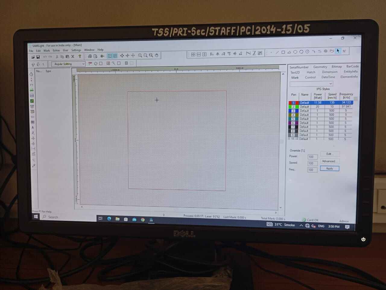
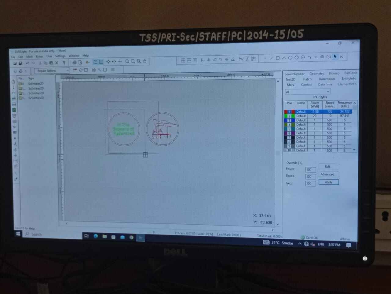
File> Import design
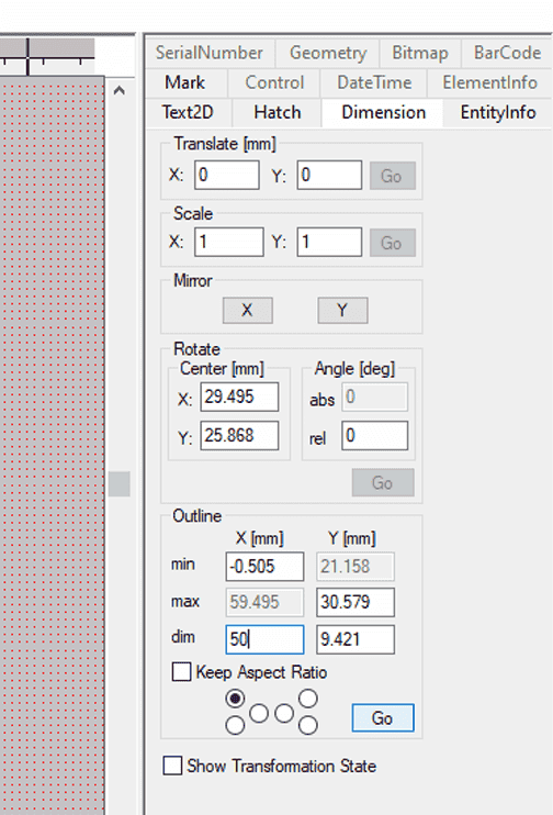
Set the Dimesion of design and external board.
Select the pen colour as your default> apply settings as in image.
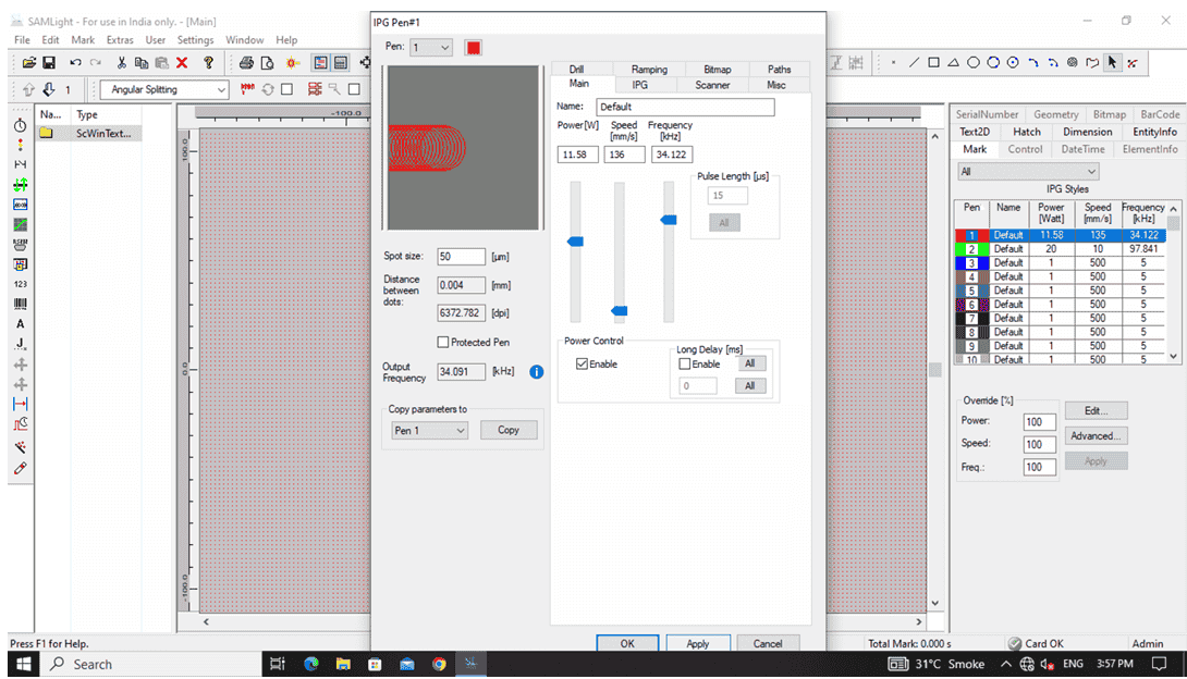
Set the highlighted blue part in the image..
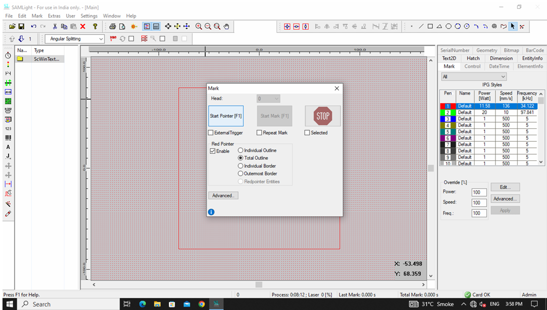
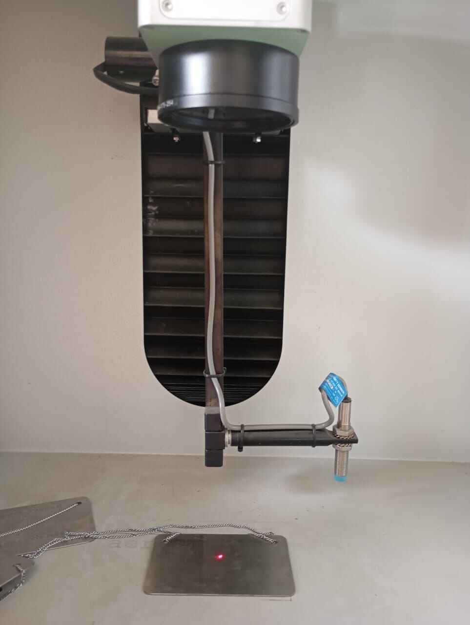
Start pointers.
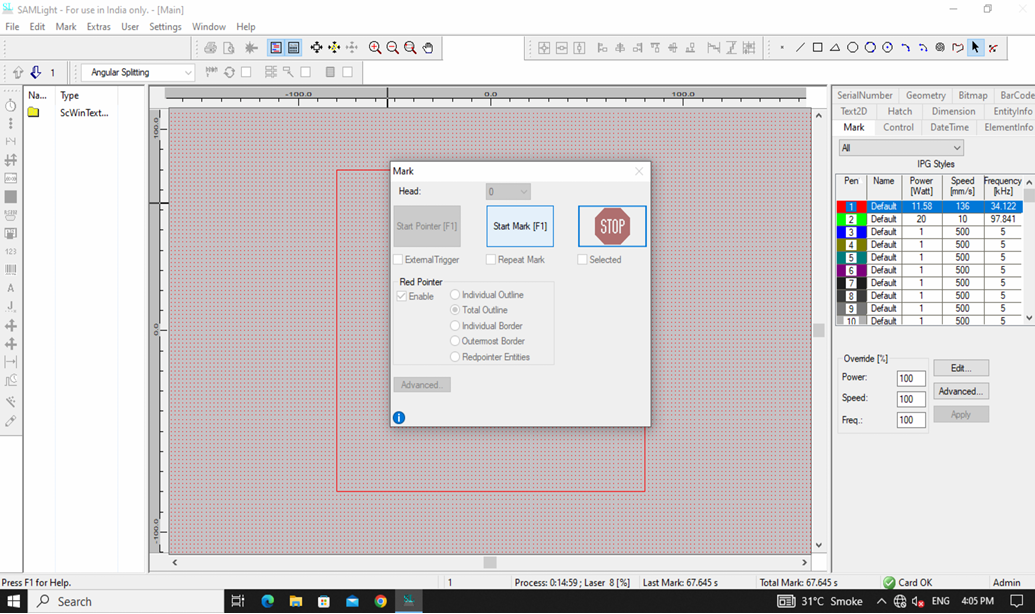
Laser Marking Machine Setup Guide
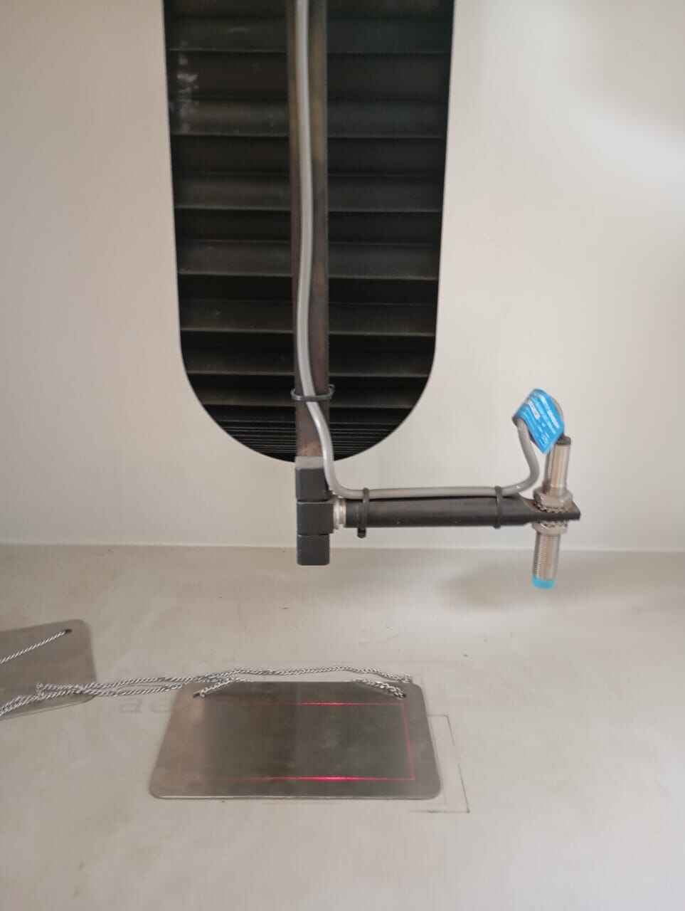
Place the plate at the centre of the beem.
The design dimension frame pops up.
Final Outcome: Hero shot

Learnings
SRM 20 is a metal engraving device which is used for building PCB. A key learning from the above metal engravinging was the metal dust particles. On the SRM20, dangerous metal dust is accumulated at the cut arena. However, on the SIL laser marking machine the laser fumes evaporated the scraped metal. Thus, it is safer to use as you arent in direct contact with the metal fumes.
Another, interesting learning in metal engraving was the liberty in experimenting with engraving thinkness. Firstly, on the guidance of my mentor, I laser engraved the metal only to a slightest which gave a very light engrave only visible in light. Later as an exploration, I tried different thickness of engraving until I got a slight burnt effect on my coin output.
Project Files
Parametric design
Metal Engraving design
Origami Vinyl cutter design
-
-
Import an Existing File:
Lens of the cutting head focusing laser beam.
Spirit level to check if the bed is straight
Focus
In a laser cutting machine, focus refers to how precisely the laser beam is concentrated on the material. The focal point is the spot where the laser beam is at its smallest and most intense, providing the best cutting or engraving results. The focus is important for cutting precision, efficiency, material thickness handling and edge quality.
Focus is controlled by adjusting the laser head height and the focal lens position. The process by which we calculated the focus is as follows:
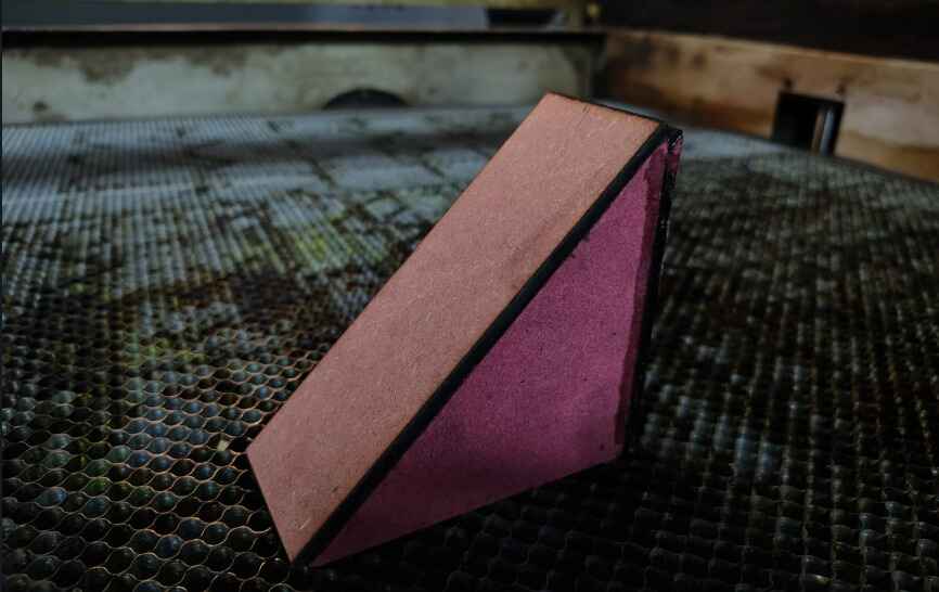
Firstly, I would like to mention here that my Fab Lab instructor Pranav Gawde , gave us an assignment to think of ways we could calculate the focus. On pondering about the same, I thought 1. We could change the bed height, but the bed size movement is not precise. 2. We could build a staircase like structure with a millimeter step distance, but the complexity of the step design increase, plus the precision of decimals is lost. 3. Finally, creating a slope, held on a hypotenuse triangle at an angle of 45 degrees, this would help us give the precision of the focus. I also reffered to my fab instructor's page, Jesal Mehta. Instead of using an scalene triangle he used the 30-60-90 degrees triangle, thus the focus length would be half thinnest line on the slope.
Note: For my focus calculation tests, I used MDF as the material to determine the optimal laser settings. Additionally, for my kerf analysis and parametric design, I utilized a 3mm acrylic sheet that was available as an unused piece in the Fab Lab. This allowed me to experiment with precision cutting and adjust my design parameters accordingly, ensuring efficient material usage while refining the accuracy of my laser-cut components.
Triangle Slope Design. 10*15*15
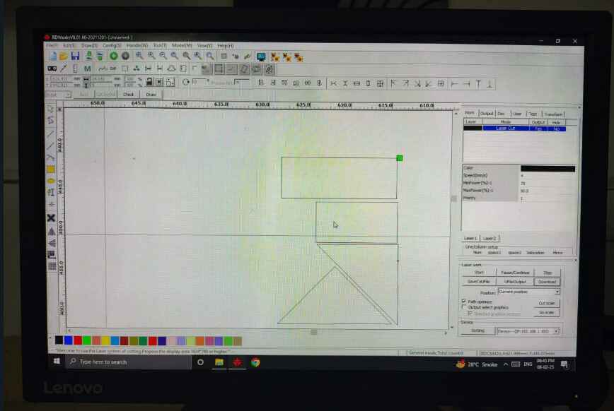
Triangle Slope Cut.
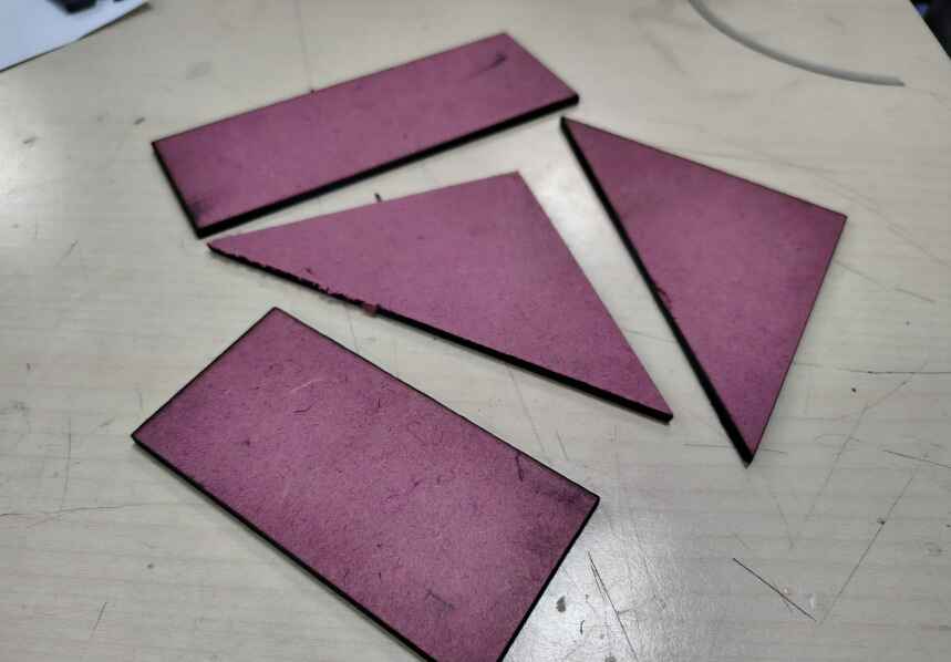
Triangle Slope.
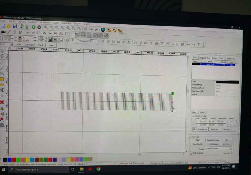
Once the device for calculating the kerf was created, we were all ready to calculate our focus. 1. We adjusted the bed height to for the laser nozzle to touch the height tip of our triangle and with the precise power and speed of laser cutter as per the 2mm mdf material that is: (Power-80, Speed-8), we drew a straight line throughtout the slope. On calculating from the start point of the kerf to the the thinnest portion of the line we got the focus at about a distance of 5mm. However, we were a bit skeptical on deciding if its 5mm/4mm. Thus we performed test number 2. we drew horizontal straight lines throughtout the slope at a distance of 1mm each, on laser cutting this design we found our focus to be 5mm precise.
Horizontal Lines Design
Learning 1.
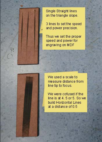
Focus length line number: 5mm
.jpg)
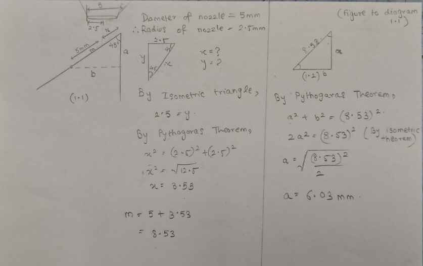
Now we had to find the actual focus distance from the nozzel tip to the material, to break it down, we calculated the hypotenuse and we needed to calculate the height. We went about this as; Include the nozzle radius in the focal length calculation of the laser cutter to account for beam convergence and precision. Adjust the formula accordingly to ensure accurate focusing. We calculated the nozzle radius affecting the focus precision.
Nozzle diameter= 5mm, radius= 2.5mm
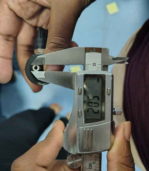
calculating focus
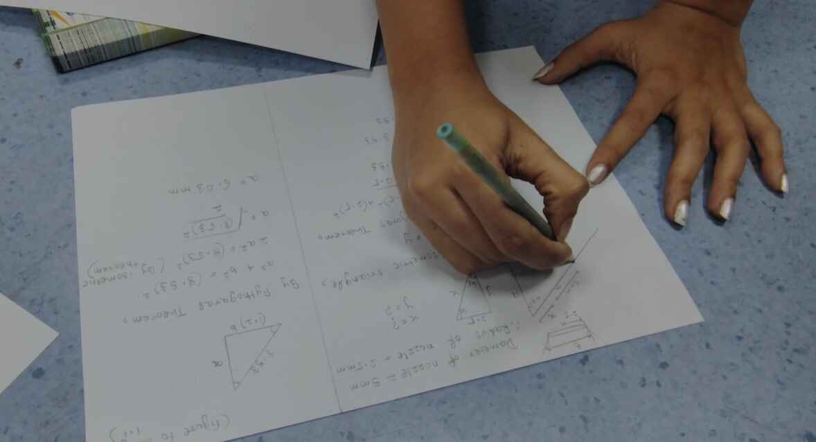
Final Focus Length= 6mm
Kerf
Kerf refers to the width of the material removed by the laser beam during cutting. It is the gap left between the cut edges and depends on factors like laser type, power, material properties, and focus settings. The focus is important for Precision in design (eg. while building mechanical joints), Material Waste, material thickness and Cut Quality.
The factors affecting kerf are:
- Laser Type & Power – Higher power lasers create wider kerfs due to increased heat dispersion.
- Material Type & Thickness –
Soft materials (wood, acrylic) have a larger kerf and
hard materials (metal) have a smaller kerf but require more power.
- Focus & Beam Diameter –
A well-focused laser produces a narrower kerf and vice-versa. Therefore, we performed the Focus test before the
kerf test.
- Cutting Speed –
Faster speed → Narrower kerf.
Slower speed → Wider kerf (more material burns away).
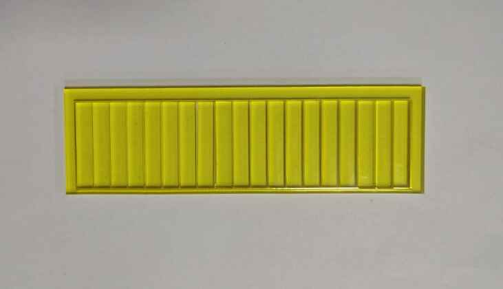
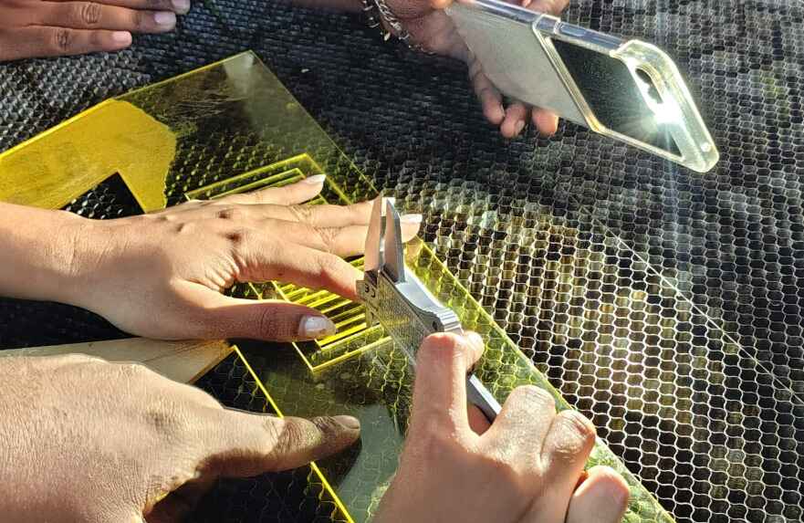
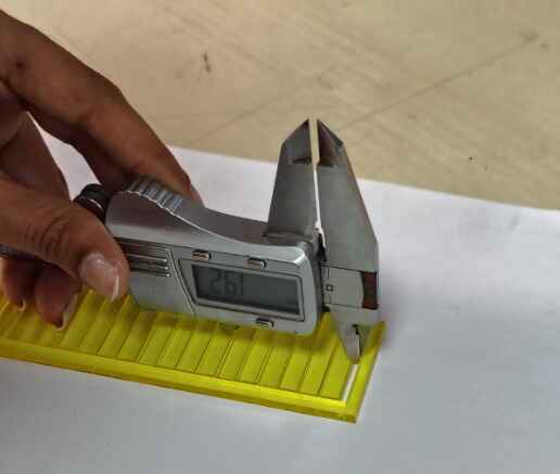
Calculating kerf, I call it the comb cut: To calculate the kerf using a comb-like mechanism,I start by creating a rectangular design file with evenly spaced line slots, each set 1 mm apart. I used Fusion 360 software to ensure precision with the measurements. Once the file was ready,I laser cut it using a controlled speed of 10 and a power setting between 60 and 80, ensuring consistency in material removal. After cutting, measure the actual distances between the slots using a vernier caliper.Finally, I Compared these measurements with the original design to determine the margin of error, which represents the kerf width. This process helps in calibrating the laser cutter for future projects requiring precise fits. Other ways of calculating the kerf is laser diameter/2.
Designing the Comb
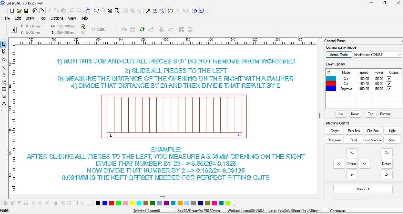
Laser cutting the comb, by cuttting on the precise focus that we calulated above.
Using Vernier caliper to calculate.
Final Kerf Length= 0.09mm
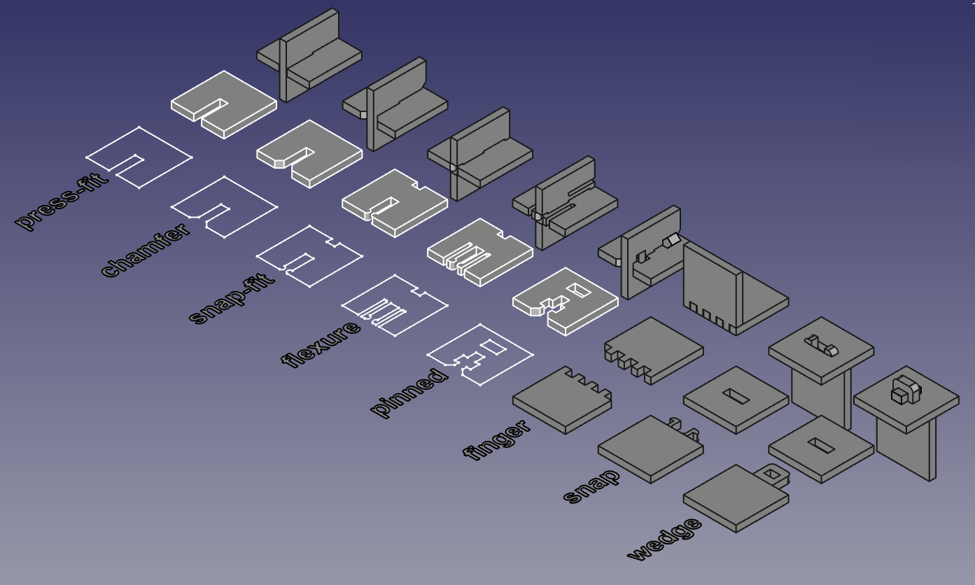
Joints
Building Joints: By accounting for the measured kerf, I worked on designing and building joints. Accounting for kerf ensures a precise, tight-fitting connection, reducing gaps and enhancing structural integrity. Proper kerf compensation prevents loose joints that may weaken over time or overly tight joints that can cause material stress. This precision improves both the durability and aesthetics of the final assembly.
Here I am learning and understanding different joints and their tolerance to kerf.
- Press-fit – A tight-fitting joint where friction holds the pieces together without adhesives or fasteners.
- Chamfer – A beveled edge is added to ease assembly and reduce stress concentrations in press-fit joints.
- Snap-fit – Uses flexible features like hooks or clips that snap into place to create a secure but removable
connection.
- Flexure – A compliant mechanism that allows bending or flexing to enable assembly or movement.
- Pinned – Uses a pin or dowel to provide rotation or a secure locking mechanism between parts.
- Finger – Interlocking tabs and slots that increase joint strength, often used in woodworking or laser-cut
assemblies.
- Snap – A locking mechanism where parts snap together with built-in retaining features for easy assembly.
- Wedge – Uses a tapered design to secure parts by applying force, increasing friction for a tight hold.
Joints
Analyzing Kerf and building joints
Chamfer joint: I worked on the Chamfer Joint, The chamfer joint is beneficial as it provides a larger surface area for adhesion, improving joint strength. It enhances aesthetics by creating smooth transitions between edges, reducing sharp corners. This joint also helps in better stress distribution, minimizing material fatigue over time. Additionally, it allows for precise alignment, ensuring a cleaner and more professional finish in assembled structures.
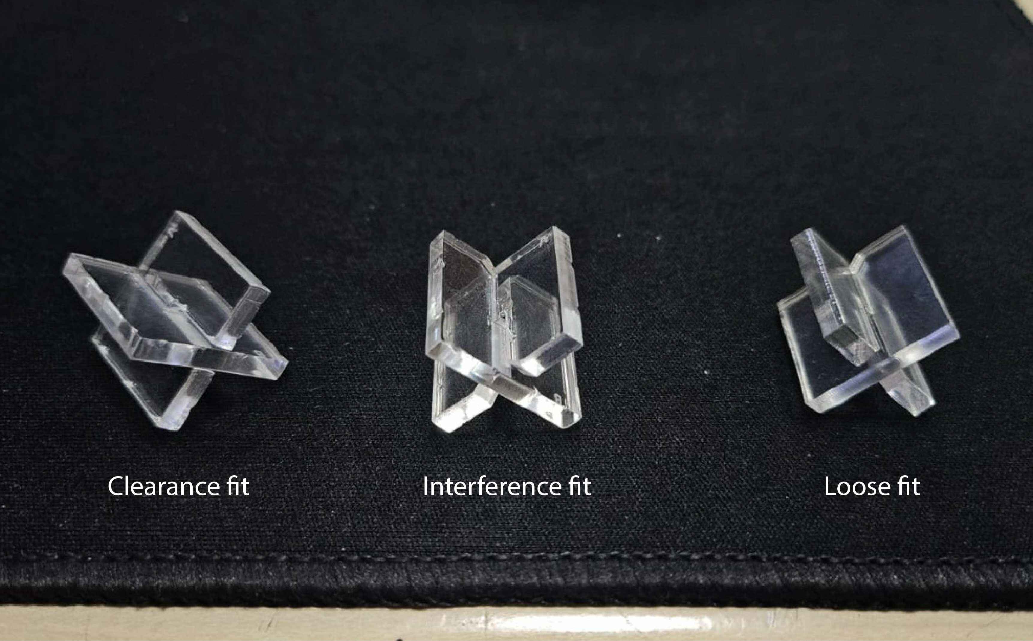
Error I made: This error stemmed from either haste or time anxiety, leading to an incorrect kerf calculation for the chamfer joint. Initially, I miscalculated by applying the kerf of each slot relative to the other, resulting in a loose fit. Realizing the mistake, I corrected it by applying the material kerf properly—deducting 0.1mm from each slot in a 3mm plywood, making the final slot measurement 2.90mm. This adjustment ensured a precise, tighter fit for the joint. However, this error helped me learn the types of fit:
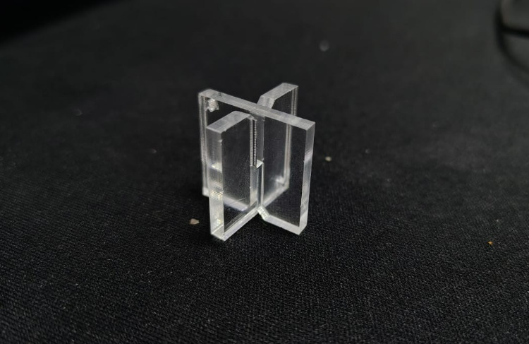
- Interference fit: Tight assembly
- Clearance fit: Precise assembly
- Loose fit: Loose assembly.
Calculating the material thickness to build the slot of my Chamfer joint.
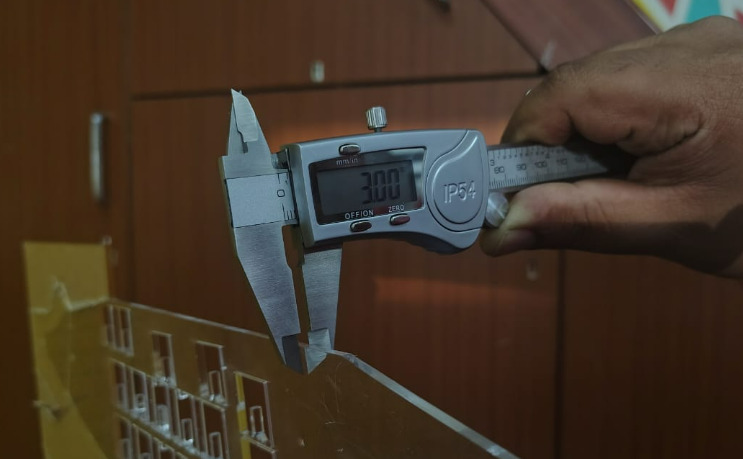
Trial and errors of the interferance, loose , clearance fit by experimenting the value of kerf.
Precise final fit was 0.09, which was precise to my kerf calculation above.
Parametric design
Parametric design is a process that uses algorithms and computational techniques to generate and manipulate complex designs based on a set of parameters and rules. Instead of manually defining every aspect of a design, you set parameters (like dimensions, angles, curves, or materials), and the system automatically updates the design when changes are made. Changes in one part of the model update all related parts automatically.It provides efficiency & flexibility so designers can experiment with multiple variations quickly. Keeping in mind the kerf valaue, material thickness and the chamfer joints precision, I set on making parametric design. Drawing inspiration from one of my favorite designers, Paul Cocksedge , I explored fluid, functional, and interactive design elements.
The work, designed as a place to sit or play, frames views of the district’s architecture within frames.
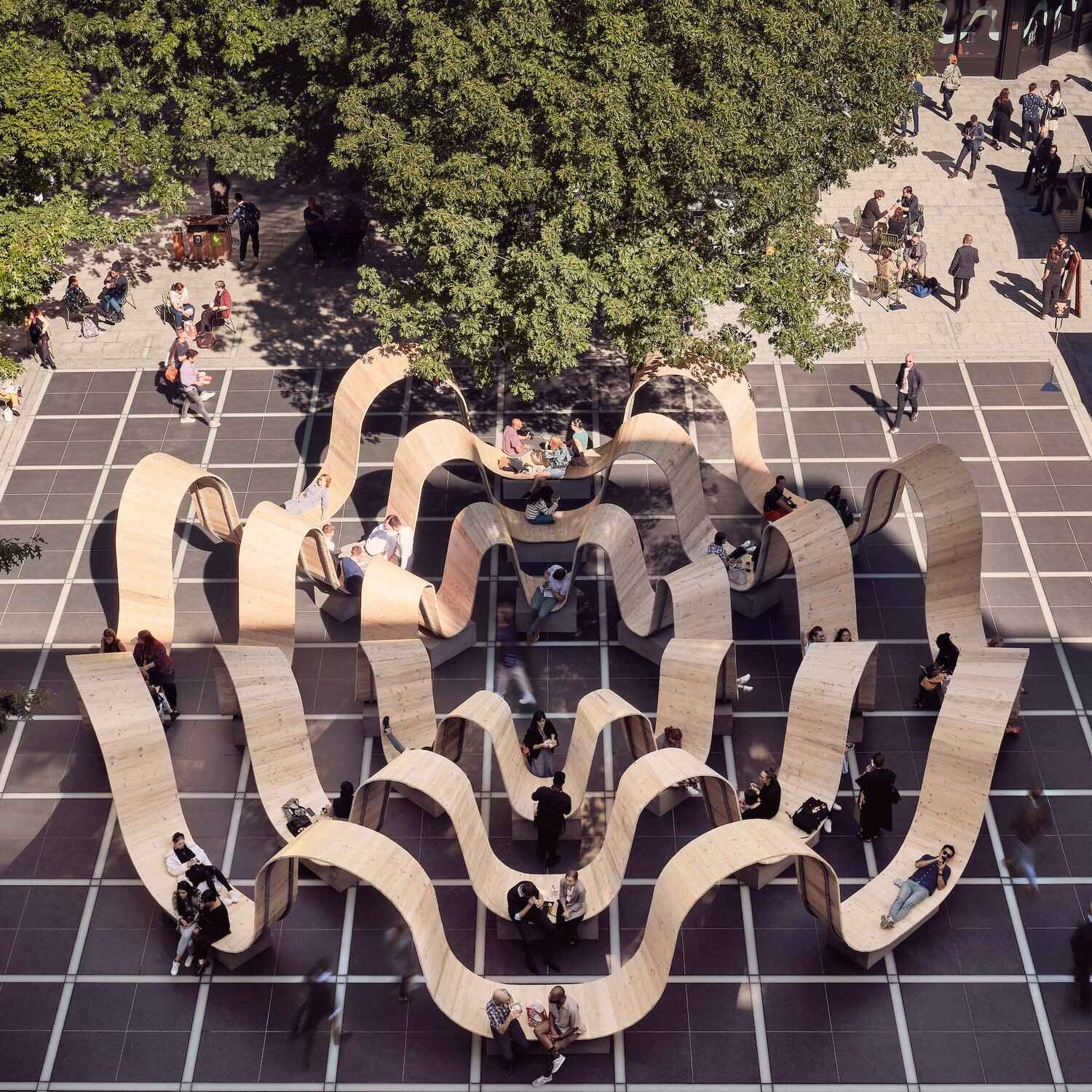
PUSH TOWER WIP: Push once for the body, two is for shade, three is for the elements and the fourth one to be for the birds.

This inspired me to make an attempt of a speculation, to build a miniature scaled version of a live size model.I attempted a parametric design of a swastik: Indian Religious symbol, evolving into a 3 by 4 swastik, as part of my exploration to create an artistic seating and bird feeder installation for public spaces. This concept merges cultural symbolism, functionality, and nature interaction, providing a space for both people and birds/ billboard which I describe below. Through CAD modeling and prototyping, I explored modular adaptability, ergonomic seating, and integrated feeding spaces, considering form suitabability for urban environments. This model represents my initial attempt at developing a public installation that encourages social engagement and coexistence with nature.
Create Sketch
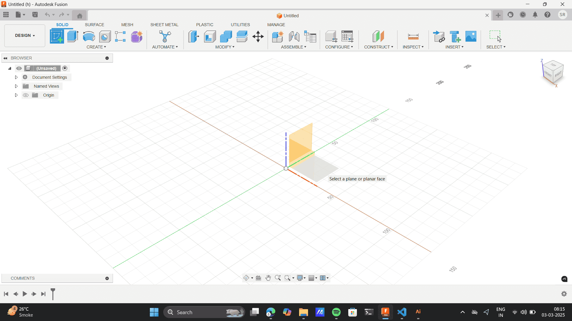
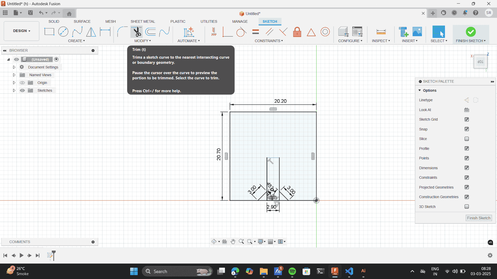
Rectangle tool
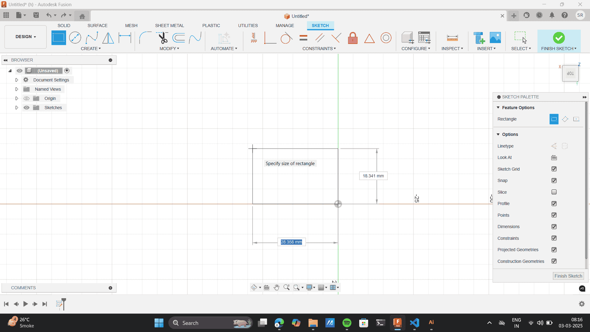
Sketch Dimensions
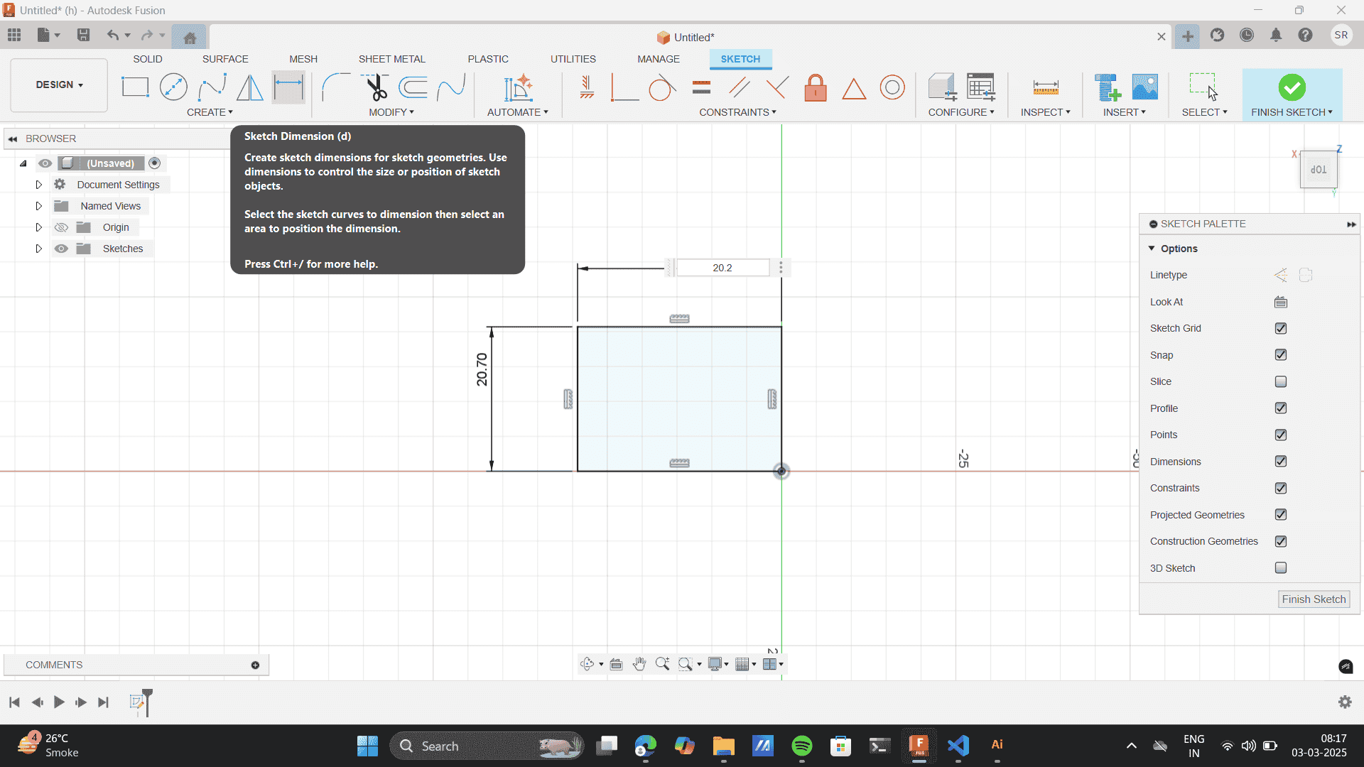
Dimensions: 20.20* 20.70
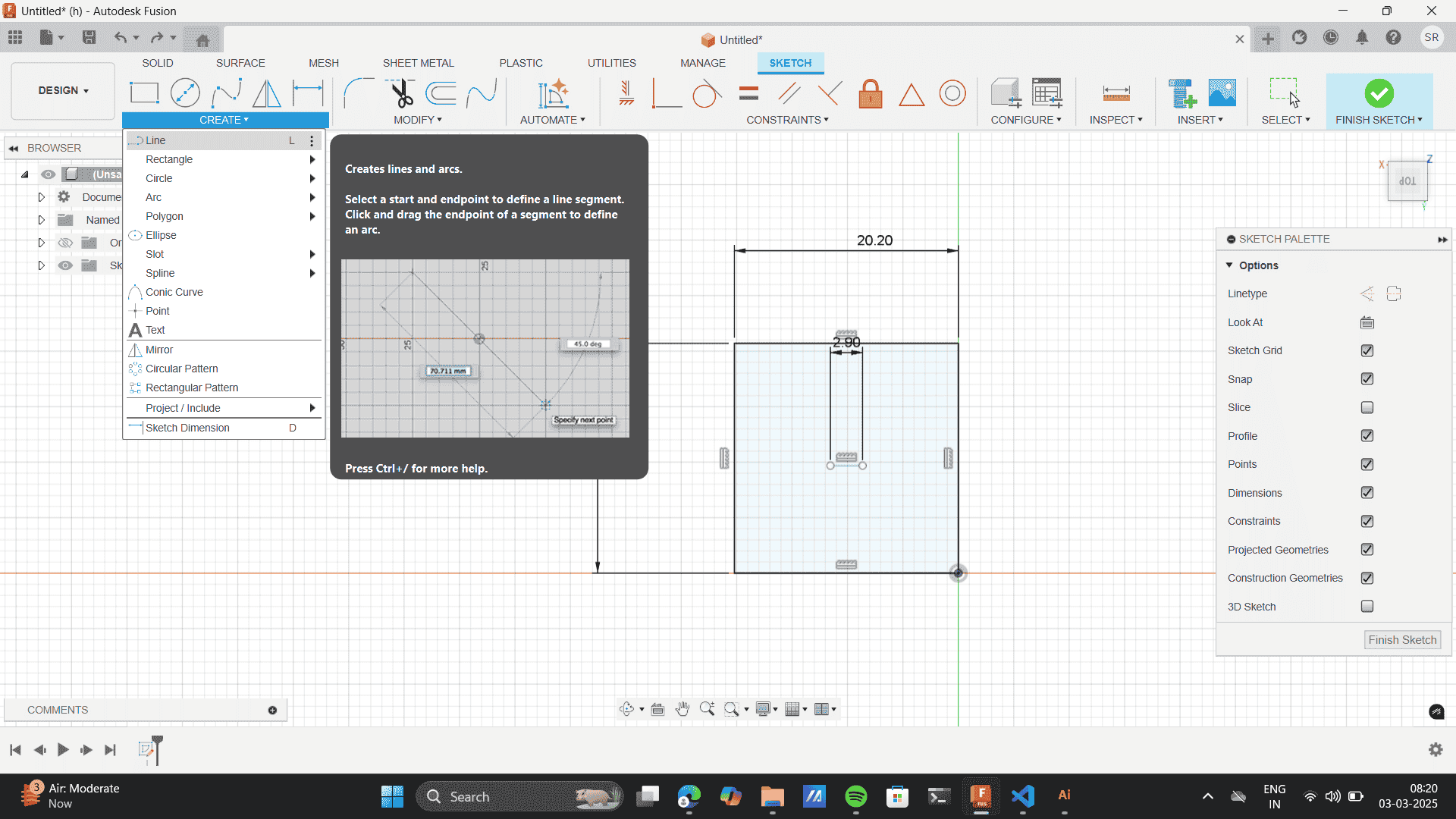
Add an internal rectangle for slot as per the material thickness- 3mm
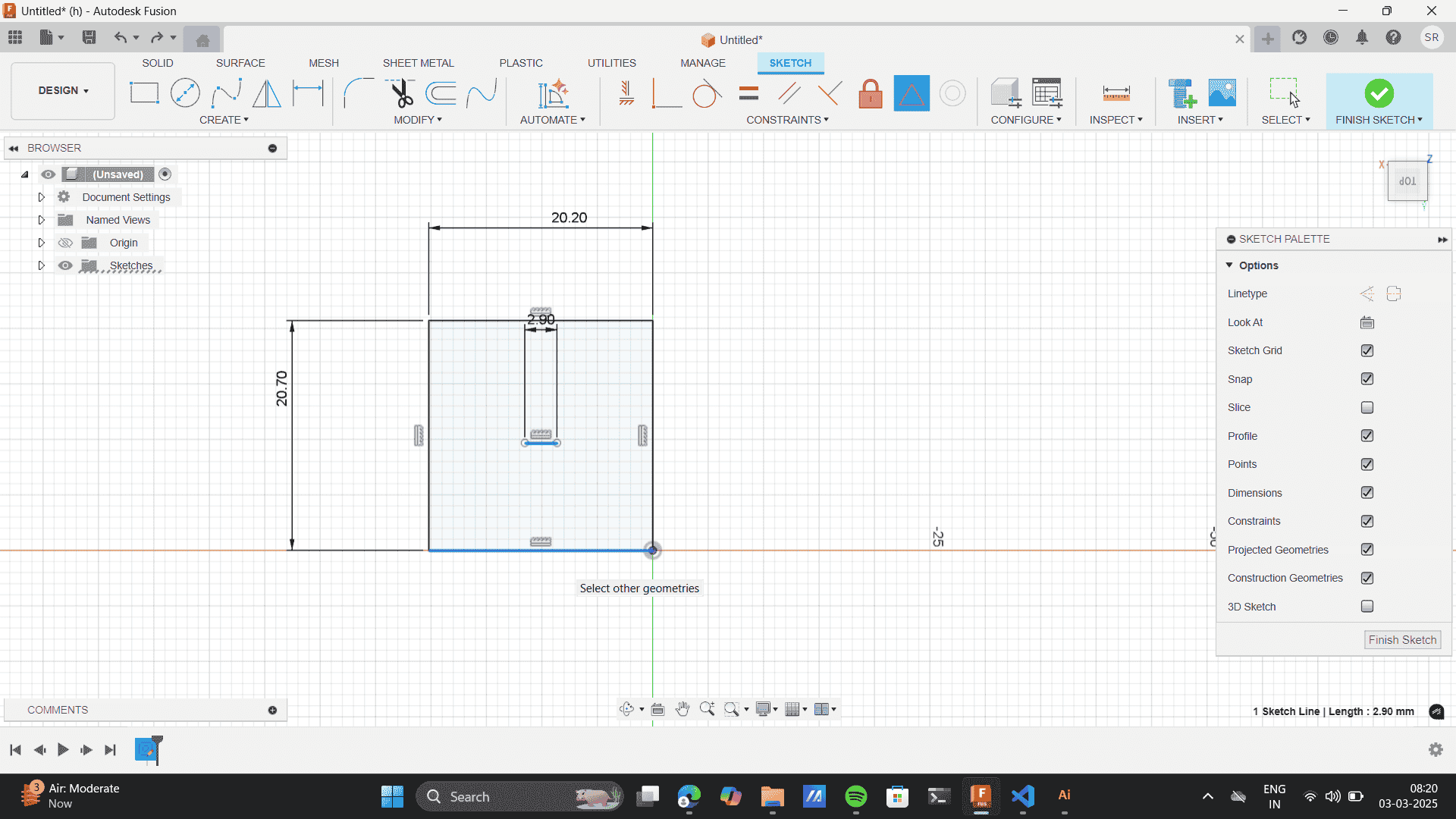
Keeping in mind the kerf of 0.09- Give a slot dimensions of 2.9.
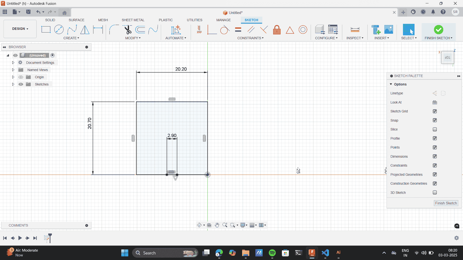
Here I, rounded off the kerf from 0.09 to 0.1 and subtracted 0.1 kerf from my material thickness of 3mm and gave a slot thickness of 2.9
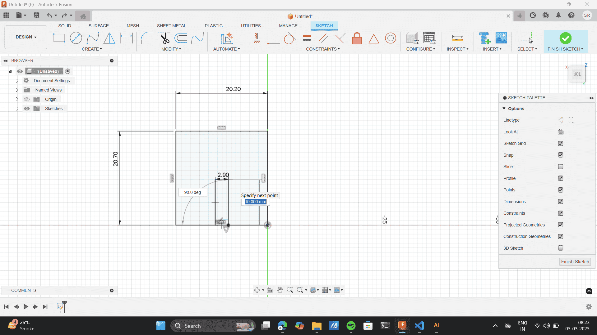
Specify the dimesions of the internal rectangle- 10mm
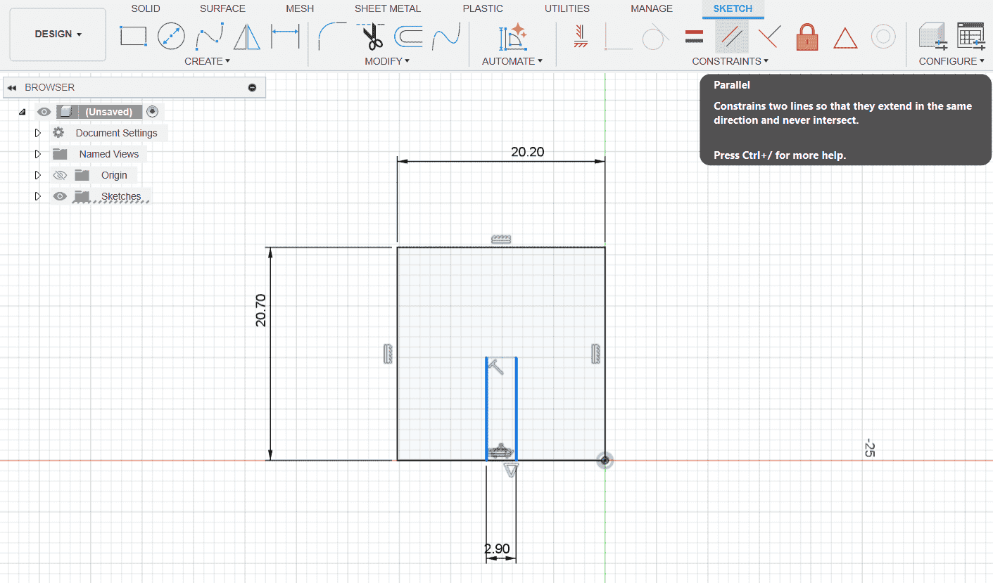
Use parallel tool to add precision in the internal slot.
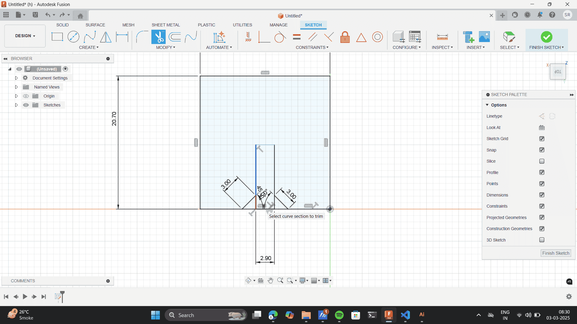
To create a chamfer add lines at an angle of 45 degrees from base.
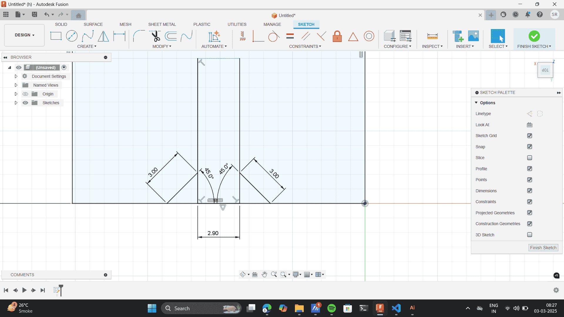
Use trim tool to erase the sketch lines.
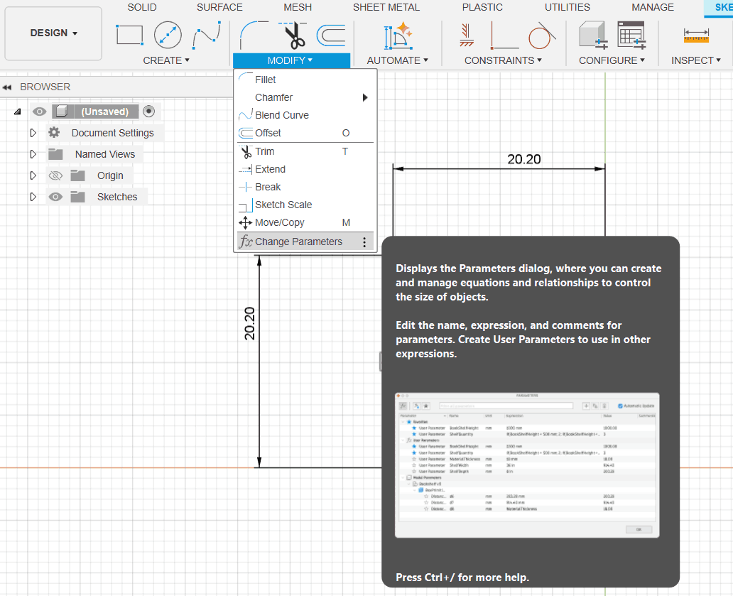
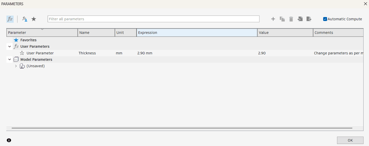
Previously I didnt set the parameters, my global instructor saw the void in my process after which I set the parameters for my parametric. Setting parameters in Fusion 360 is super useful when you want to make your designs parametric—so changes in dimensions automatically update the whole model. Settings the parameters, Benefits of setting the parameters: Designs adapt automatically. If your material thickness changes, just update the parameter and all dependent dimensions will adjust. Here's how you can set them up:
Modify> Change parameters
Set a new parameter, by clicking on the " + Add " feature.
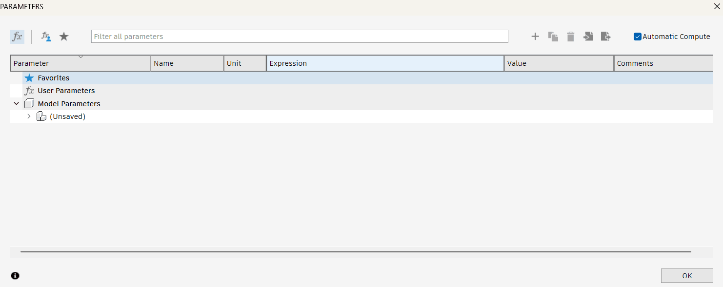
Set the parameters to 2.90 as the slot thickness for a material of 3mm as the kerf that we calculated was 0.09
Describe the user parameter.
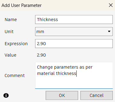
Added the parameter for slot as per the thickness of material.
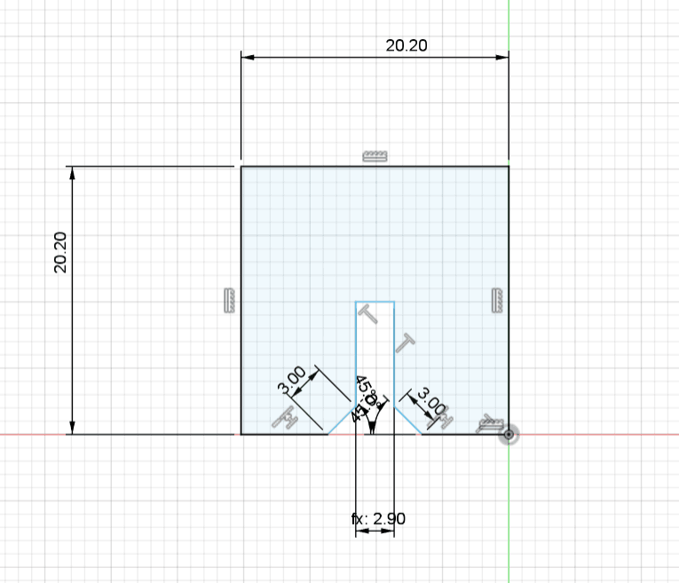
Select the slot> Control+ D> "Thickness 2.90mm."
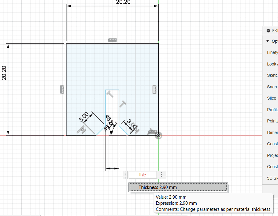
Thus, set the thickness as per the material and will change as material changes.
Trim out to build the structure.
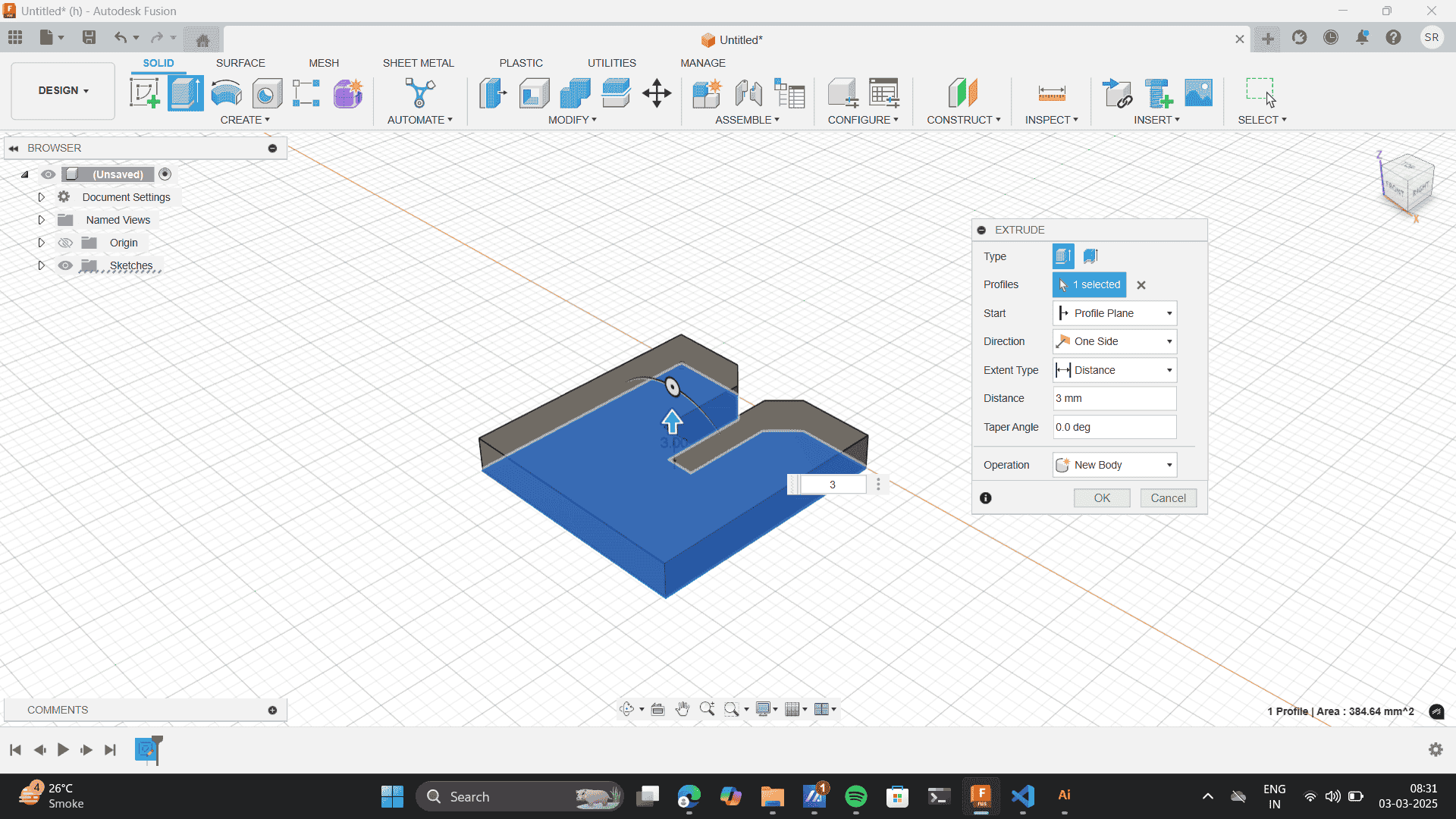
Extrude to the thichness of the material- 3mm
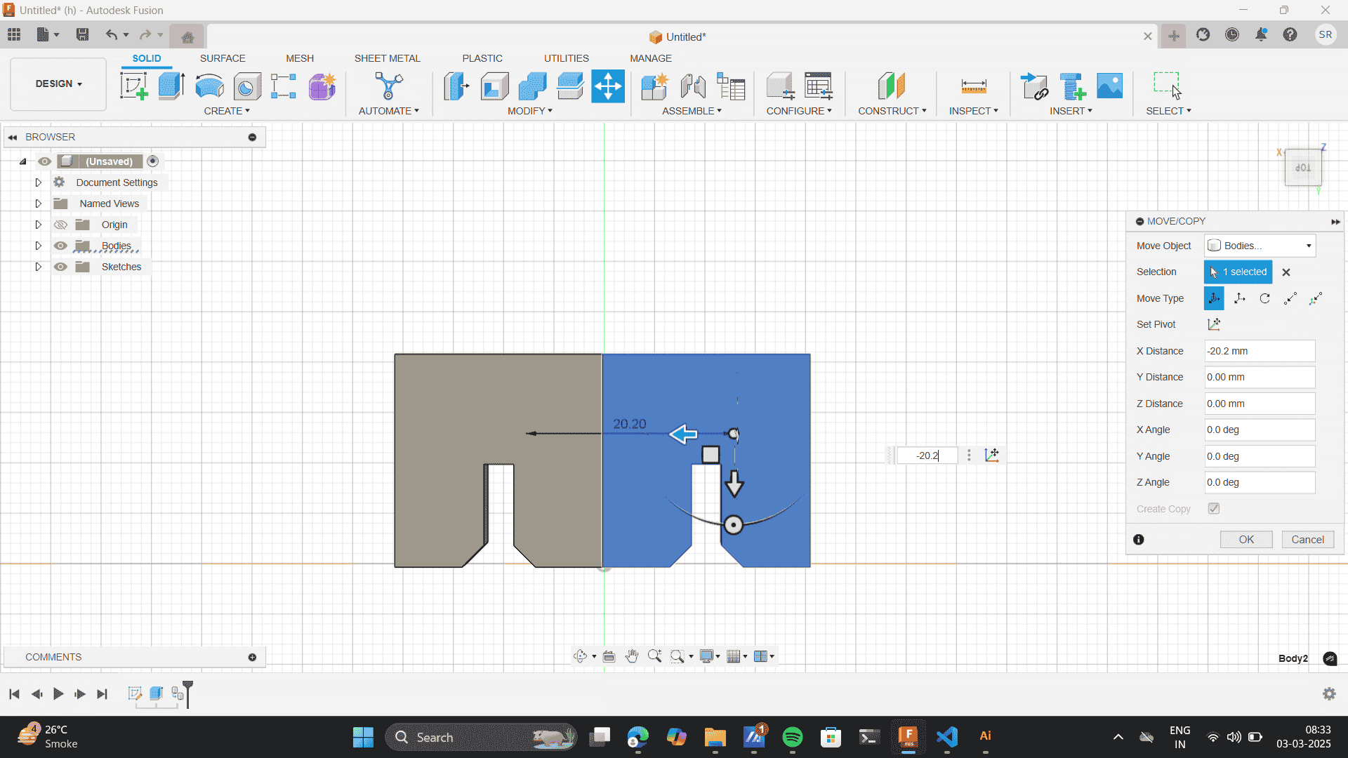
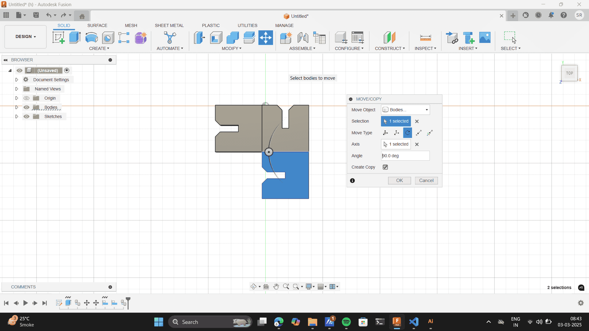
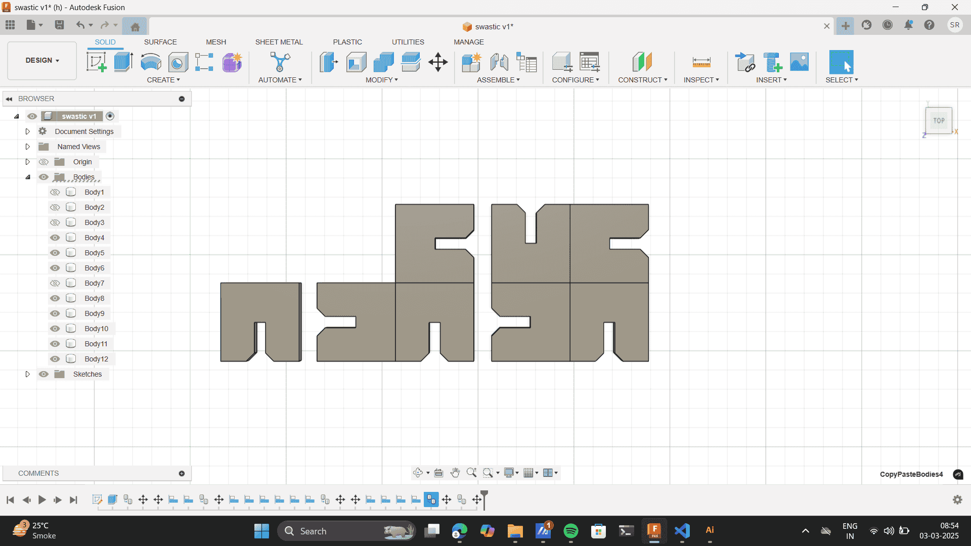
Use the move tool to copy the body.
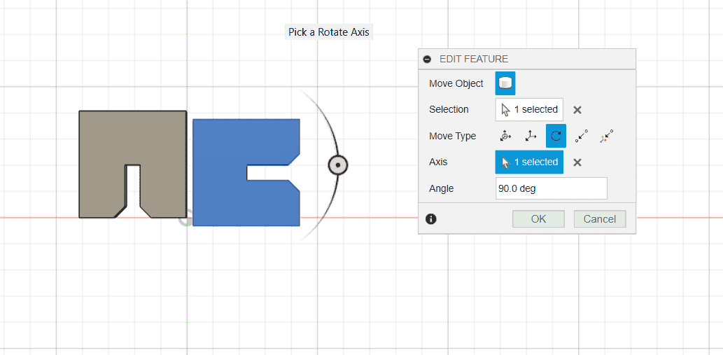
Rotate the moved object to an angle of 90 degrees.
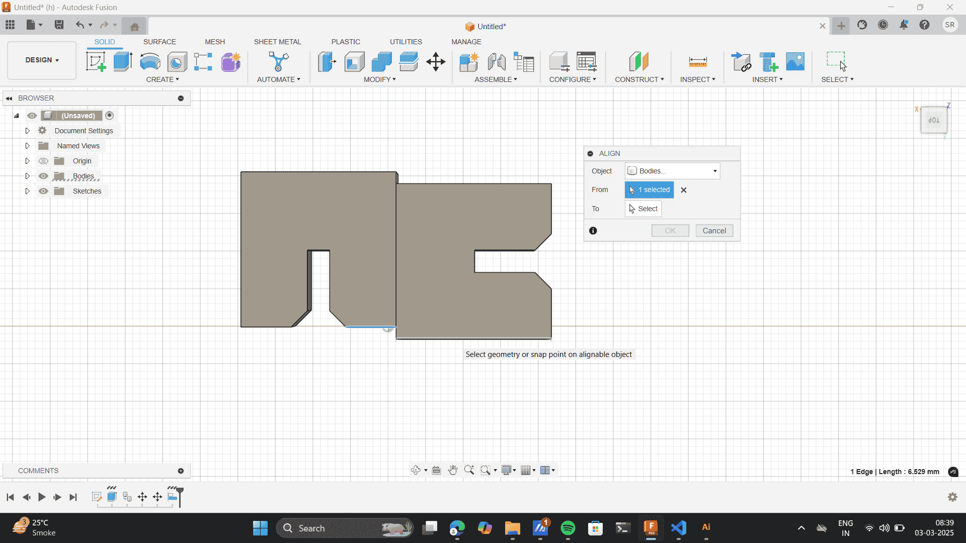
Modify> align tool.
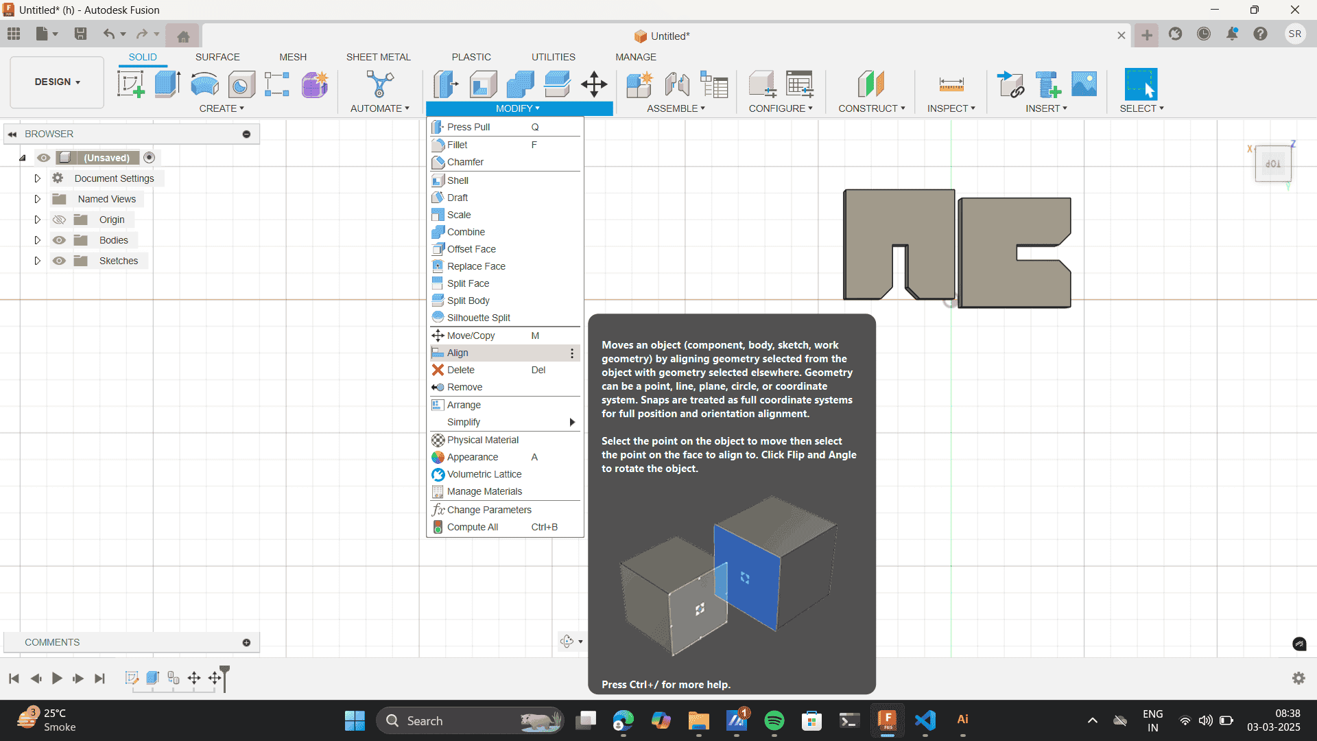
Align the sides of the two bodies.
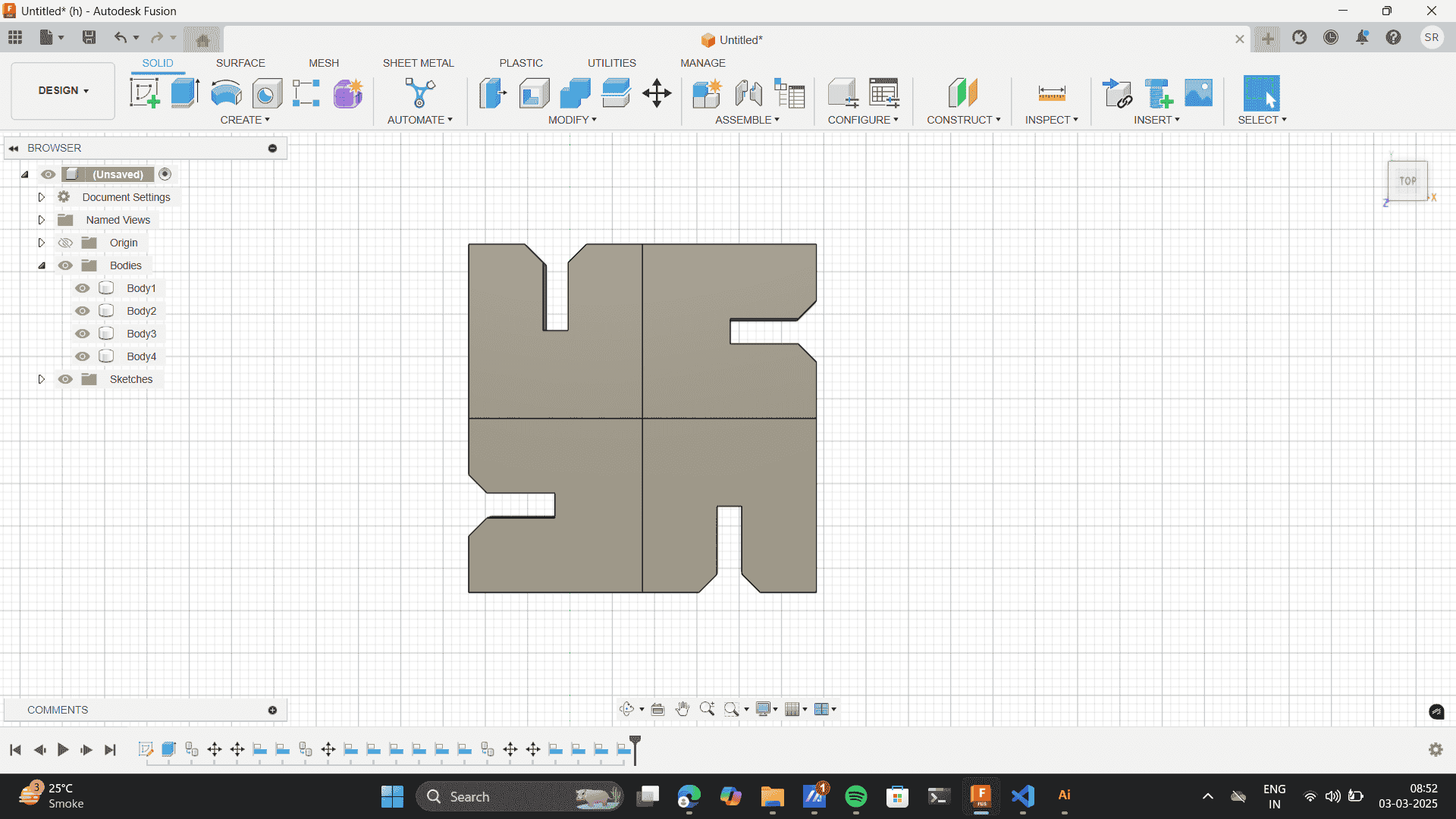
Repeat the process to form the blow pattern
Finally, the swastic shape is created.
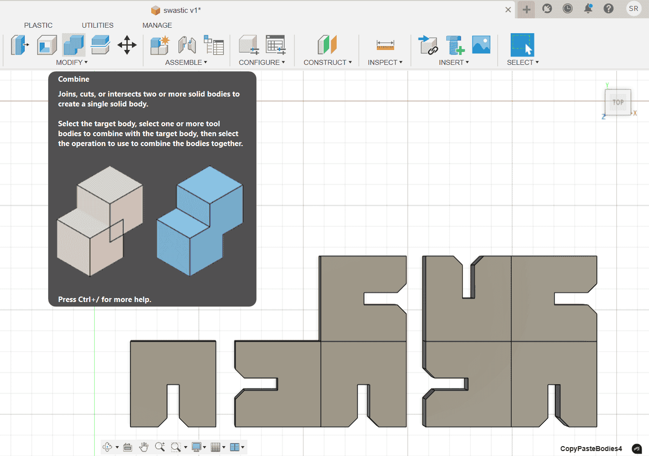
Exploring- Subtracting a body creates a new shape
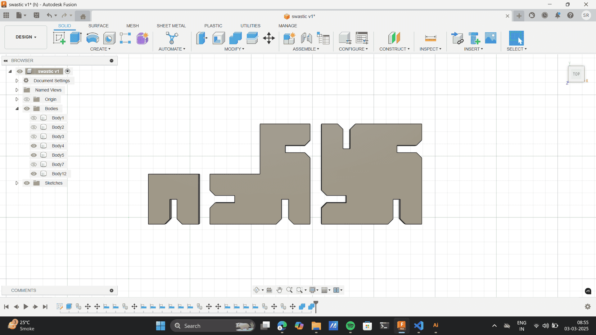
Merge tool- merge every separate body to one body
My Parametric Design:
.png)
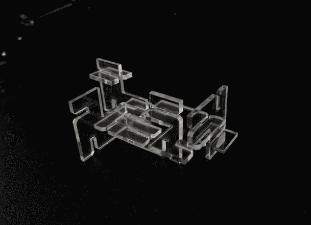
.jpg)
.jpg)
Vinyl Cutter
To begin with the fundamentals, the Vinyl cutter I worked on and studied was from the Riidl FabLab
Vinyl Cutter- GRAPHTEC Cutting Plotter CE7000. For better undertanding of the vinyl cutter refer to the Standard
Operating Procedure (SOP) for Riidl lab Vinyl cutter as a pdf:
Riidl Laser Cutter SOP (PDF)
.jpeg)
Difference between vinyl cutter and laser cutter: Unlike laser cutting, which burns through materials, a vinyl cutter uses a sharp blade to slice through thin films with extreme accuracy. This makes it ideal for cutting materials like adhesive vinyl, heat transfer vinyl, and thin foils without causing heat damage or charring. Since the process is entirely mechanical, it ensures clean, precise edges without any discoloration, making it perfect for applications like stickers, decals, and intricate signage. Additionally, vinyl cutters are more efficient for handling flexible and delicate materials that might otherwise warp or melt under the high temperatures of a laser cutter
The Graphtec Cutting Plotter CE7000 is a high-precision vinyl cutter used for cutting stickers, decals, labels, and heat transfer materials. It has Advanced Cutting Precision supporting contour cutting with high accuracy. Also, it has advanced connectivity with USB, Ethernet, and barcode support for automated cutting. It has media compatibility with various materials, including
Setting Up the Vinyl Cutter
Vinyl Cutter Blade:
Position the vinyl under the machine’s rollers
Undertanding Interface.
Software
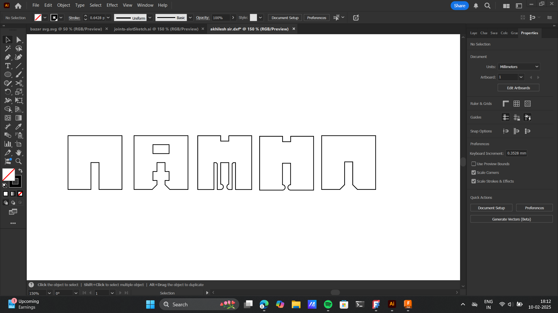
This vinyl cutter is complatible with the Graphtec Studio 2 Software. You can download Graphtec Studio 2 from the official Graphtec website. Link to download. It’s available for both Windows and Mac. It provides tools for vector-based design, text editing, and precise cutting control, making it an essential interface between your digital design and the vinyl cutter. Steps for Using Graphtec Studio with a Vinyl Cutter: Preparing the Vector File:
- Create or obtain a DXF or SVG vector file for cutting.
For my assignment, I used a Batman SVG available online.
- Connecting to the Vinyl Cutter:
Open Graphtec Studio software to establish a connection with the Graphtec vinyl cutter.
- Opening the Design File:
Go to the File menu and select Open to import the DXF or SVG file into the software.
- Using Image Trace (Optional):
If working with an image (JPEG, PNG), you can load it into Graphtec Studio.
Use the Image Trace option to convert it into a vector for cutting.
- Preview & Final Adjustments:
Ensure the design is properly sized and positioned.
Make any necessary modifications before sending it to the cutter.
I enjoyed the printing process thus I went on printing a new sticker: I have added a detalied overview of my Graphtec Studio 2 sotware usage on my week 2 documentation. Check the Link here