Week 11: Embedded Networking and Communications
🔗 Link to Group Assignment
See the Group Assignment Page for Embedded Networking and Communications.
Introduction to Communications
Communication is the foundation for interaction between devices in embedded systems. It allows multiple boards to send and receive data, synchronize actions, and share information. In this context, networking protocols define how this data is transferred and how devices understand one another. Understanding and implementing communication protocols is essential in the field of digital fabrication and robotics.
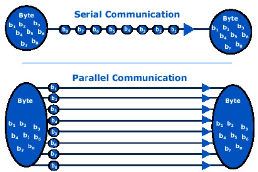
There are two major types of communications in electronics:
- Parallel Communication: Multiple data bits are sent simultaneously over multiple wires. It is fast but requires more I/O pins and wiring complexity.
- Serial Communication: Data is sent one bit at a time over a single wire. It is slower than parallel communication but more efficient for long distances and limited pin availability.
Within serial communication, there are several protocols:
- UART (Universal Asynchronous Receiver-Transmitter): Uses TX and RX lines for bidirectional communication. It’s simple, requires no clock line, and is common in microcontrollers.
- I2C (Inter-Integrated Circuit): Uses two wires (SDA for data and SCL for clock). Allows multiple devices with unique addresses to communicate on the same bus.
- SPI (Serial Peripheral Interface): A faster protocol using four wires (MISO, MOSI, SCK, and SS). It is commonly used for sensors and displays.
- CAN (Controller Area Network): Used in automotive and industrial environments, allows robust communication between many nodes with fault tolerance.
- Wireless Protocols: Such as Wi-Fi, Bluetooth, LoRa, and Zigbee, used for remote communication without physical connections.
What is UART?
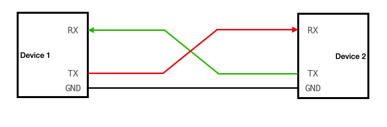
UART (Universal Asynchronous Receiver-Transmitter) is a hardware communication protocol used for asynchronous serial communication. It works by transmitting data serially, bit by bit, using just two wires: TX (transmit) and RX (receive). UART does not require a clock signal; instead, both devices must agree on a baud rate (bits per second) to synchronize data exchange.
It is widely used because of its simplicity, and is especially useful when two devices need to communicate directly, like in this week’s assignment.
Objective of the Week
The objective was to establish communication between two boards using the UART protocol. One board (Xiao RP2040) sends a command via UART when buttons are pressed, and the other board (Xiao ESP32S3) receives the command and controls servomotors accordingly. All programming was done using the Arduino IDE.

These diagrams were essential for ensuring proper communication and motor control connections.
Addressing and Wiring
TX from the RP2040 is connected to GPIO16 (RX) of the ESP32S3. GND is shared between both boards to ensure a common reference voltage.
Communication Protocol
I used UART, a basic and reliable protocol that only requires a TX pin, RX pin, and a shared ground (GND). Both boards communicated at 9600 baud. Commands were sent as single ASCII characters:
- L → Move servos left (180°)
- R → Move servos right (0°)
- S → Move servos to center (90°)
Xiao RP2040 – Sender
What it does:
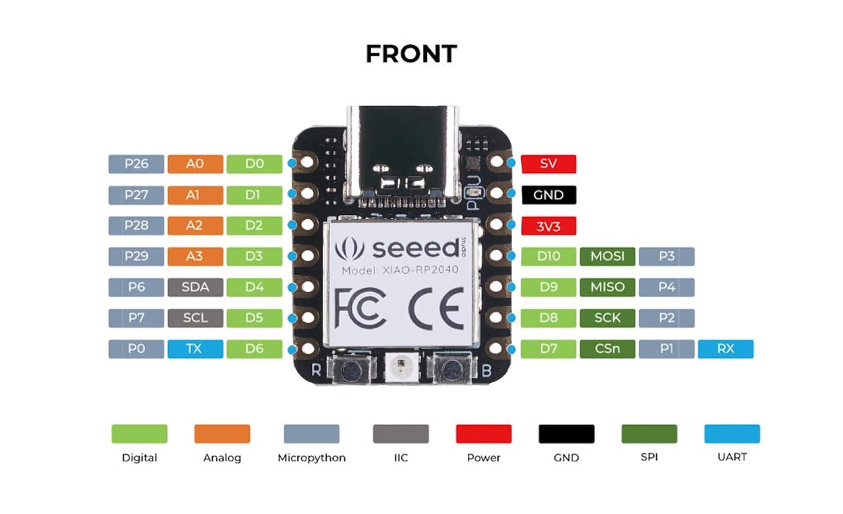
I used the Xiao RP2040 to read the state of three buttons. Depending on which button is pressed, it sends a single character via Serial.write() through its TX pin.
Wiring:
| Button | RP2040 Pin |
|---|---|
| Right | D10 |
| Left | D9 |
| Center | D8 |
Code
Xiao ESP32S3 – Receiver and Servo Control
What it does:
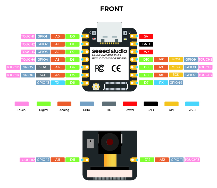
I used the Xiao ESP32S3 to receive UART commands via Serial1 on GPIO44 (RX). The board listens for characters and moves three servos connected to D2, D3, and D4. I also enabled USB Serial to print the received commands for debugging.| Button | RP2040 Pin |
|---|---|
| Right | D10 |
| Left | D9 |
| Center | D8 |
Why I built it this way:
I decided to split the system into input (RP2040) and output (ESP32S3) boards to keep the logic modular and clean. Sending simple one-letter commands makes the communication efficient and easy to debug. I chose GPIO44 for RX because it’s compatible with Serial1, and I kept USB serial free for monitoring. The ESP32Servo library lets me control servos with precise PWM using a range from 500 to 2500 µs, ensuring good accuracy and smooth motion.
Code
Result
I successfully achieved UART communication between the two boards. Button presses on the RP2040 were correctly interpreted by the ESP32S3, and all three servos responded instantly. The system was stable and easy to debug thanks to the USB serial output showing received commands in real time.
Problems and Fixes
- Initially, the servos didn't move: this was due to incorrect wiring and baud mismatch.
- The RX pin on the ESP32S3 was not correctly set: fixed by specifying GPIO16.
- Buttons gave wrong readings: resolved using INPUT_PULLUP and checking for LOW when pressed.
Learning Outcome
By completing this week’s assignment, I was able to successfully establish UART communication between two embedded boards. I learned how to properly wire and configure pins for UART, send and receive serial commands, and control servomotors based on these commands. I also practiced splitting system functionality across two microcontrollers for modularity and used
🔄 I2C Communication Test Between Xiao RP2350 (Master) and RP2040 (Slave)
After testing UART communication, I explored using the I2C protocol to establish communication between the RP2350 (as the master) and the RP2040 (as the slave). I2C is ideal for communicating with multiple devices over just two wires (SCL and SDA).
🧪 Test Objective
The RP2350 sends a byte periodically to the RP2040 over I2C. The RP2040 receives the command and makes a servo motor move between 0°, 90°, and 180° as confirmation of proper data reception.
🔌 Wiring
| Signal | RP2350 | RP2040 |
|---|---|---|
| SDA | D4 | D4 |
| SCL | D5 | D5 |
| GND | GND | GND |
| Servo Signal | – | D0 |
Both boards were powered via USB, and the servo was powered from an external regulated 5V lab power supply (sharing GND).
🔍 I2C Connection Test
Before implementing the servo control, I performed a simple I2C communication test between the RP2350 (master) and the RP2040 (slave). The goal was to verify that both boards were properly connected and able to exchange basic signals.
1️⃣ RP2040 (Slave at 0x08) – Code
This code makes the RP2040 flash its internal LED (pin 25) every time it receives a byte via I2C. It also prints a confirmation message when powered up.
#include <Wire.h>

#define I2C_ADDR 0x08
#define LED_PIN 25    // Internal LED

void receiveEvent(int howMany) {
  digitalWrite(LED_PIN, HIGH);
  delay(100);
  digitalWrite(LED_PIN, LOW);
}

void setup() {
  pinMode(LED_PIN, OUTPUT);
  Wire.begin(I2C_ADDR);         // Start as slave at address 0x08
  Wire.onReceive(receiveEvent); // Trigger on data received
  Serial.begin(115200);
  Serial.println("RP2040 slave ready at 0x08");
}

void loop() {
  delay(1000); // Optional debug loop
}
2️⃣ RP2350 (Master) – Code
This code sends a single byte (0x42) every second to the RP2040. The Serial Monitor prints "Conected" if the connection is successful, or an error code otherwise.
#include <Wire.h>

#define SLAVE_ADDR 0x08

void setup() {
  Wire.begin();         // Start as I2C master
  Serial.begin(115200);
}

void loop() {
  Serial.print("Ping to 0x");
  Serial.print(SLAVE_ADDR, HEX);
  Serial.print(" ... ");

  Wire.beginTransmission(SLAVE_ADDR);
  Wire.write(0x42);               // Send any byte
  byte err = Wire.endTransmission();

  if (err == 0) {
    Serial.println("Conected");
  } else {
    Serial.print("Error "); Serial.println(err);
  }

  delay(1000);
}
🔎 Expected Result
- The RP2040’s internal LED flashes briefly on each I2C message received.
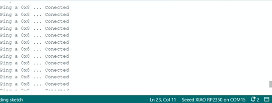
- In the RP2350 Serial Monitor, the following appears:
Ping to 0x8 ... Conected
Ping to 0x8 ... Conected
If instead you see something like Error 2, it indicates a wiring issue or the slave is not detected.
This successful test confirmed that I2C communication between both boards was functioning, and I could proceed with implementing data-based actions like servo control.
📟 RP2350 (Master) Code
This board initiates I2C communication by sending a single byte every second to the RP2040 (address 0x08):
#include <Wire.h>
#define SLAVE_ADDR 0x08

void setup() {
  Wire.begin();  // Master mode
  Serial.begin(115200);
}

void loop() {
  Wire.beginTransmission(SLAVE_ADDR);
  Wire.write(0x01); // simple byte trigger
  Wire.endTransmission();
  Serial.println("Sent command to RP2040");
  delay(1000);
}
⚙️ RP2040 (Slave) Code
This board listens on I2C address 0x08. When a byte is received, it rotates the servo through 0°, 90°, and 180°.
#include <Wire.h>
#include <Servo.h>

#define I2C_ADDR 0x08
Servo myServo;

void setup() {
  myServo.attach(0); // D0 pin
  myServo.write(90); // initial position
  Wire.begin(I2C_ADDR);
  Wire.onReceive(receiveEvent);
  Serial.begin(115200);
}

void loop() {
  delay(100); // idle loop
}

void receiveEvent(int bytes) {
  if (Wire.available()) {
    byte b = Wire.read();
    myServo.write(0);
    delay(500);
    myServo.write(90);
    delay(500);
    myServo.write(180);
    delay(500);
    Serial.println("I2C data received, moved servo");
  }
}
📽️ Demonstration
🛠️ Problems Encountered
- The servo initially vibrated but didn’t move: resolved by powering it with a regulated 5V supply, not from the board.
- Wrong I2C address: verified correct 0x08 address on the slave side.
- Missing GND connection: essential for I2C to work.
📘 What I Learned
This experiment reinforced the importance of correct electrical grounding, consistent address mapping, and power management when using servos with microcontrollers. I also practiced the basics of I2C protocol and the use of Wire.h to establish two-way communication between boards.