12. Mechanical design, machine design
This was a hard week in which we had to design in teams a cnc. The teams were made random and each one had to do a different part for the cnc. I was in charge of the electronics
CNC Electronics – Development and Prototyping
Here you can see all the work each team member did to finish this proyect. Team 3 CNC
When the team was created we gave each other a task based on our strengths. I was given the electronics, because i had already designed a pcb to controll 2 nemas and also because i'll be using parts of the hardware on my final proyect
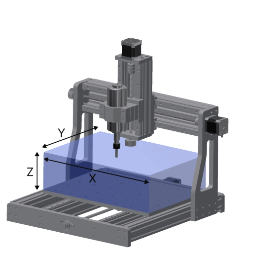
Introduction to CNC
CNC (Computer Numerical Control) machines are automated tools controlled by a microcontroller or computer that interprets G-code to move motors precisely along defined paths. They are commonly used in manufacturing and prototyping for cutting, drilling, milling, and engraving operations. CNC systems typically operate along three axes (X, Y, Z) and rely on stepper motors or servos for motion control.
The electronics in a CNC machine play a critical role in interpreting commands and converting them into movement through drivers and actuators. Proper voltage regulation and component selection are crucial to ensure consistent operation and avoid hardware failure.
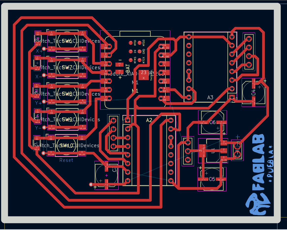
PCB Design and First Prototype
For the electronics, I started by designing the first PCB prototype in which I considered using two A4988 stepper motor drivers for X and Y axis movement. For the Z axis, we used a 20g servo motor. I had to use a 5V voltage regulator to power the servo due to its current consumption. The power input for the system is 12V, which is required to drive the stepper motors efficiently.
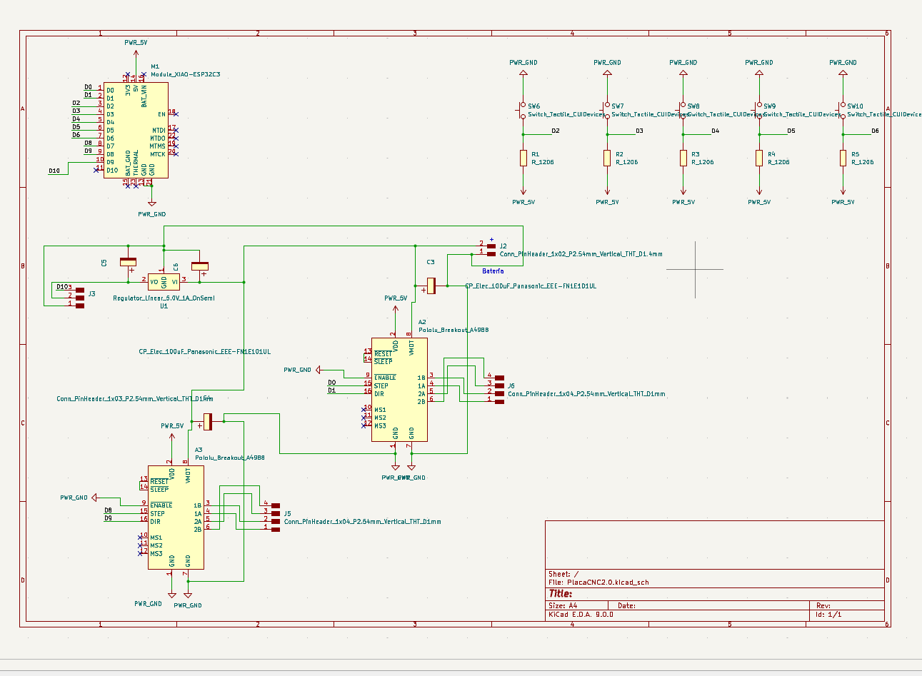
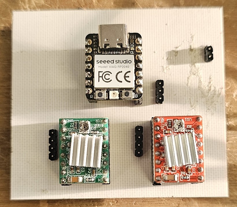
Microcontroller Selection
We decided to use a Seeed Studio XIAO ESP32-C3 as our microcontroller. It is compact, easy to use, and has enough GPIO pins for all necessary inputs and outputs, including control signals for drivers, the servo motor, and user interface buttons.
Manual Controls
To allow physical control over the stepper motors and to set the origin point, I added five buttons in a pull-up configuration: four of them to control the X and Y axes manually, and the fifth to set the machine’s origin.
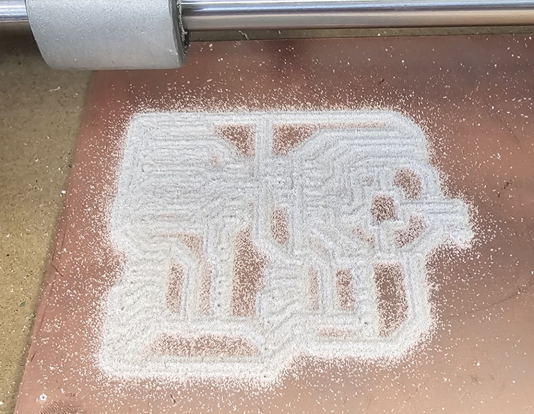
Manufacturing the PCB
After completing the wiring and layout, I exported the SVG files for the copper traces, drill holes, and edge cuts. These were then processed on a Roland CNC SMR-20 milling machine to fabricate the PCB.
First Test and Regulator Failure
Once the CNC milling process was complete, I proceeded to solder all the components in place. Unfortunately, I didn’t take a picture of the finished PCB. During testing, the 5V regulator burned out due to excess current draw. Everything worked except the servo, which was affected by the voltage regulator.
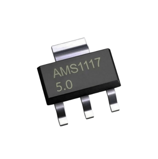
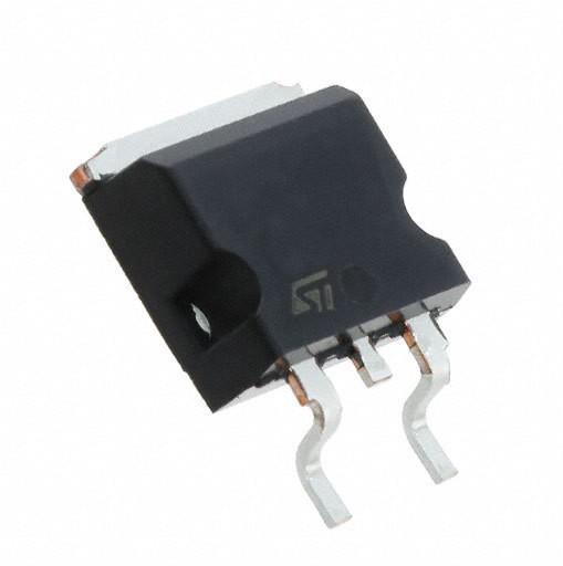
Initially, I was using an AMS1117 regulator in a SOT-223 package, which is limited to a maximum output current of 1A. This was insufficient for the servo motor. I searched for a regulator that could handle at least 1.5A and found one in a D2PAK package. However, this new component was significantly larger, so I had to redesign the PCB to accommodate the new part.
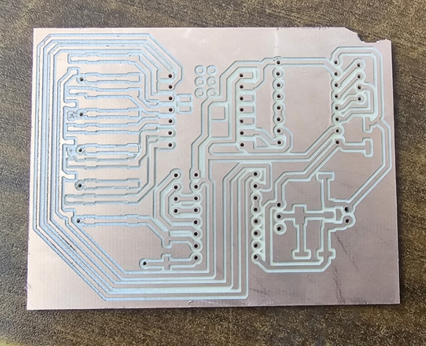
Second PCB Version and Final Testing
I repeated the process: redesigned the PCB, regenerated the SVG files, milled the board, and soldered the new components. The second version was successful, and I was very pleased with the final appearance of the PCB.
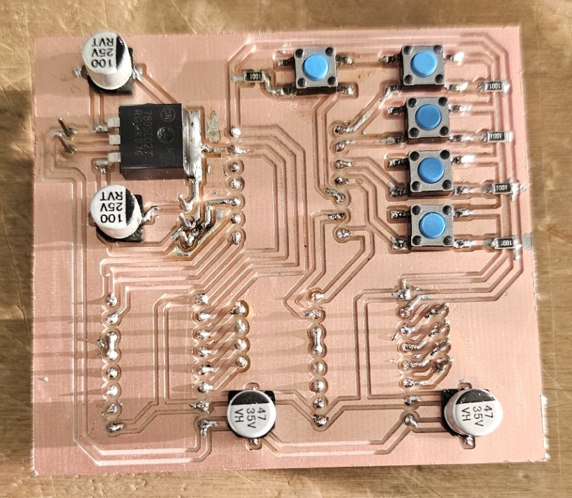
During initial testing, I encountered minor issues due to incomplete solder joints, likely caused by a lack of soldering paste. After reworking the connections, I observed current being draw on the power supply, confirming that the circuit was functioning correctly.
I uploaded a test program to the XIAO C3 using the Arduino IDE. The code successfully moved the stepper motors and the servo from right to left. All buttons worked as expected, confirming that the system was operating correctly.
    #include Servo.h>
		const int dirPin1 = D6;
		const int stepPin1 = D5;
		const int dirPin2 = D8;
		const int stepPin2 = D7;
		const int servoPin = D0;
		Servo myServo;

		const int stepsPerRevolution = 200;

		void setup() {

		  pinMode(dirPin1, OUTPUT);
		  pinMode(stepPin1, OUTPUT);
		  pinMode(dirPin2, OUTPUT);
		  pinMode(stepPin2, OUTPUT);

		  myServo.attach(servoPin);
		}

		void loop() {

		  digitalWrite(dirPin1, HIGH);
		  digitalWrite(dirPin2, HIGH);
		  for (int i = 0; i < stepsPerRevolution; i++) {
			digitalWrite(stepPin1, HIGH);
			digitalWrite(stepPin2, HIGH);
			delayMicroseconds(800);
			digitalWrite(stepPin1, LOW);
			digitalWrite(stepPin2, LOW);
			delayMicroseconds(800);
		  }
		  myServo.write(0);
		  delay(1000);

		  digitalWrite(dirPin1, LOW);
		  digitalWrite(dirPin2, LOW);
		  for (int i = 0; i < stepsPerRevolution; i++) {
			digitalWrite(stepPin1, HIGH);
			digitalWrite(stepPin2, HIGH);
			delayMicroseconds(800);
			digitalWrite(stepPin1, LOW);
			digitalWrite(stepPin2, LOW);
			delayMicroseconds(800);
		  }

		  myServo.write(90);
		  delay(1000);
		}
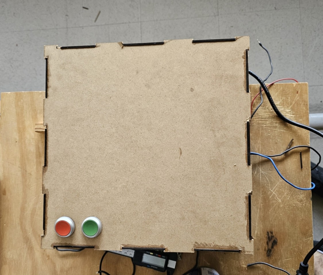
Power Supply (5V / 12V / 24V)
For the cnc Assignment I had to build a power supply system. I had 3 different power supply so I wanted to combine them into one with all necesary protections.
Components Used
- 1x 120V AC to 24V DC Power Supply
- 1x 120V AC to 12V DC Power Supply
- 1x 120V AC to 5V DC Power Supply
- 1x Three-pole Circuit Breaker
- 1x Contactor
- 1x Red Stop Push Button
- 1x Green ON Push Button
- AC Power Strip
- Tools and jumper wires for assembly
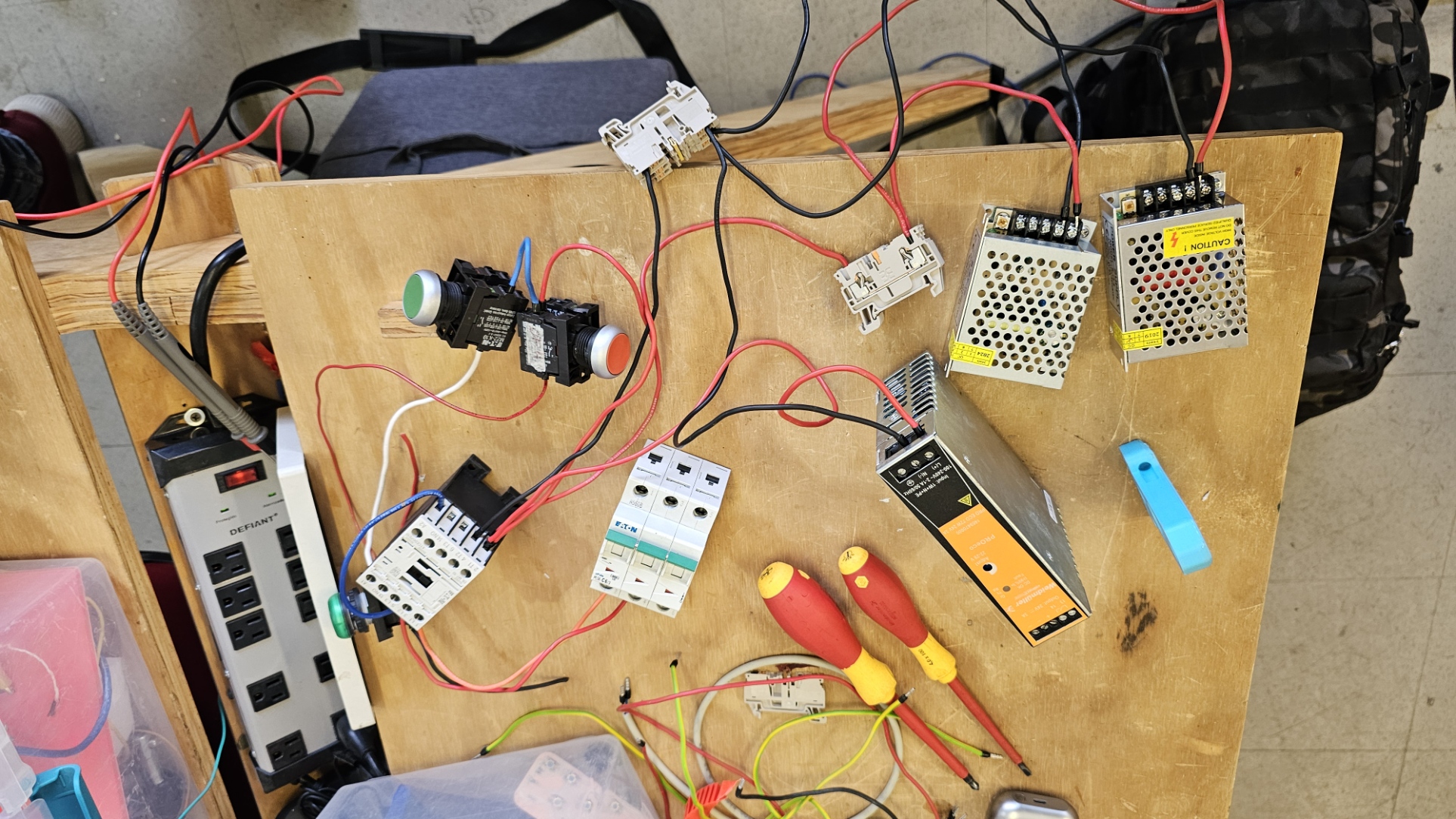
Wiring Description
- AC Input: Power is taken from a surge-protected power strip.
- Protection: Up to 220V line, it goes first into a three-pole circuit breaker for protection.
- Control: The line then passes through the stop red button and a green ON button, which controls a contactor. This setup allows me to safely cut or enable power to the whole system.
- Distribution:
- The contactor output is connected to all three DC power supplies.
- Output terminals are made accessible for easy connections to devices.
Applications
- Powers the servo motor (5V)
- Power the PCB (The xiao C3, A4988 drivers and step motors) (12V)
- Powers the DC motor for the cutting (24V)