2. Computer Aided Design
Welcome to my second week of this journey!
2D modeling
This week we started by learning new 2D and 3D design softwares. Lets start with 2D software call Inkscape.
Inkscape
I'm not a graphic designer and I've never used Inkscape or 2D software. It wasn't hard to use, if you're new like me learning the basics will be easy.
First, we create a new project. To start drawing you have to see the toolbox located on the left side of the page. For me the basics are the next ones.
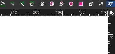
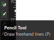
Then we locate the Pencil tool which you use it to start drawing.
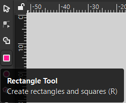
If you want to use a more precise tool to make circles or boxes you can use these tools as seen in the next images.

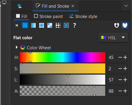
Once you made your shape you can change the colors in the right part of the page.
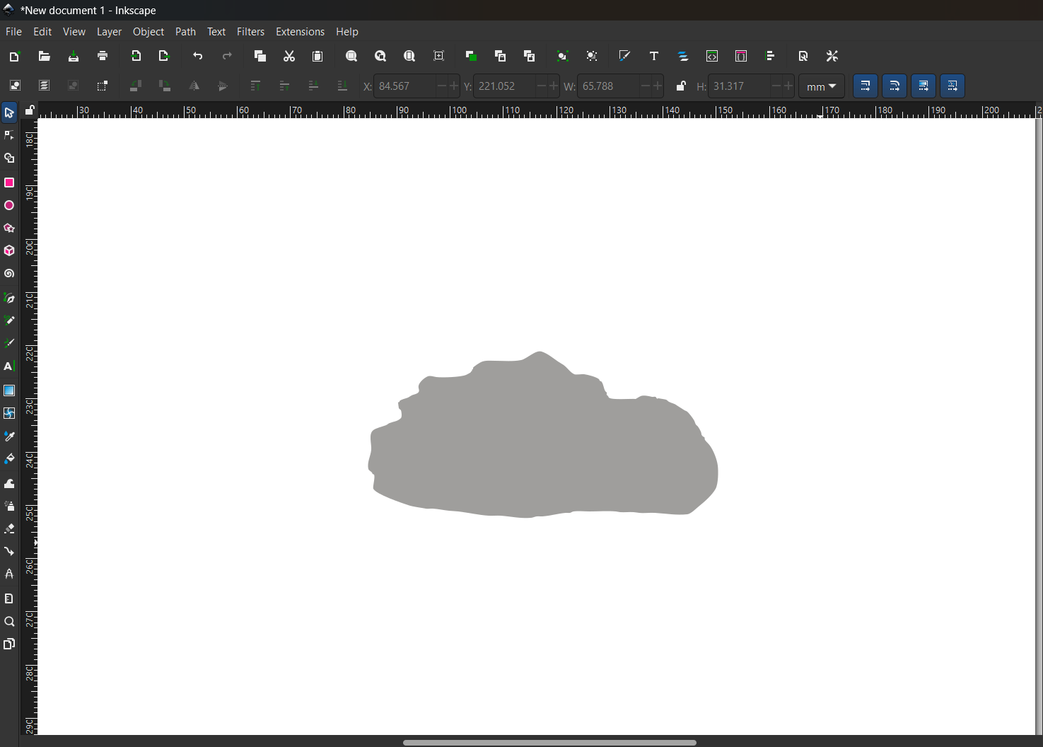
Using these basics, I was able to create my first image. This is the base.
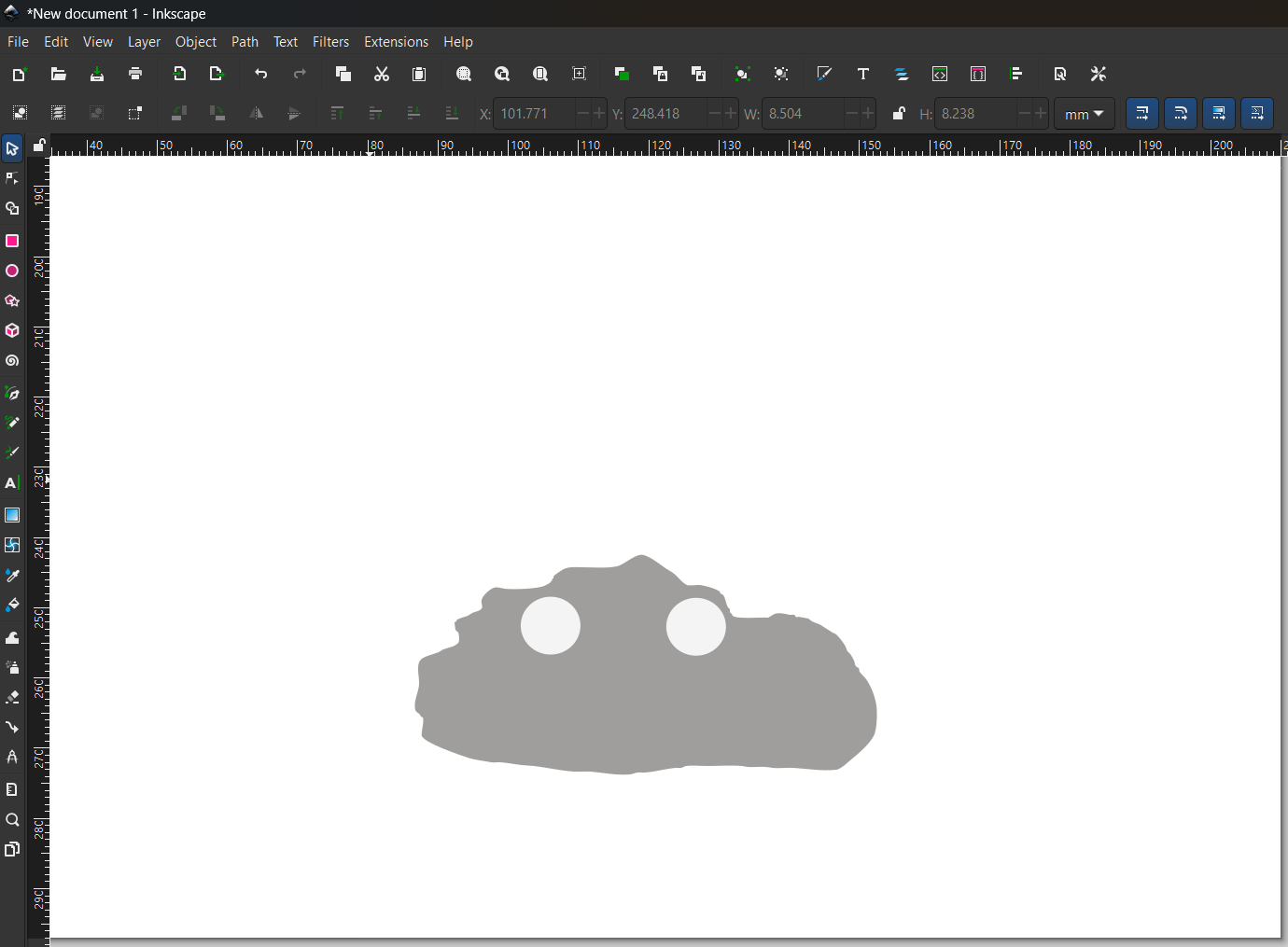
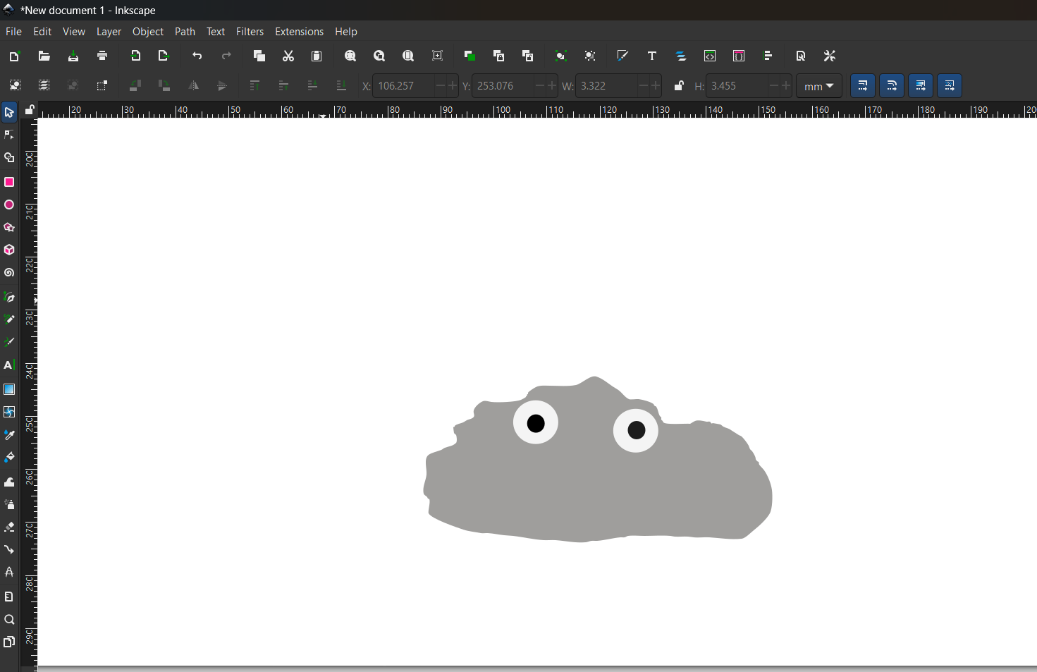
I use the circle tool for the eyes.
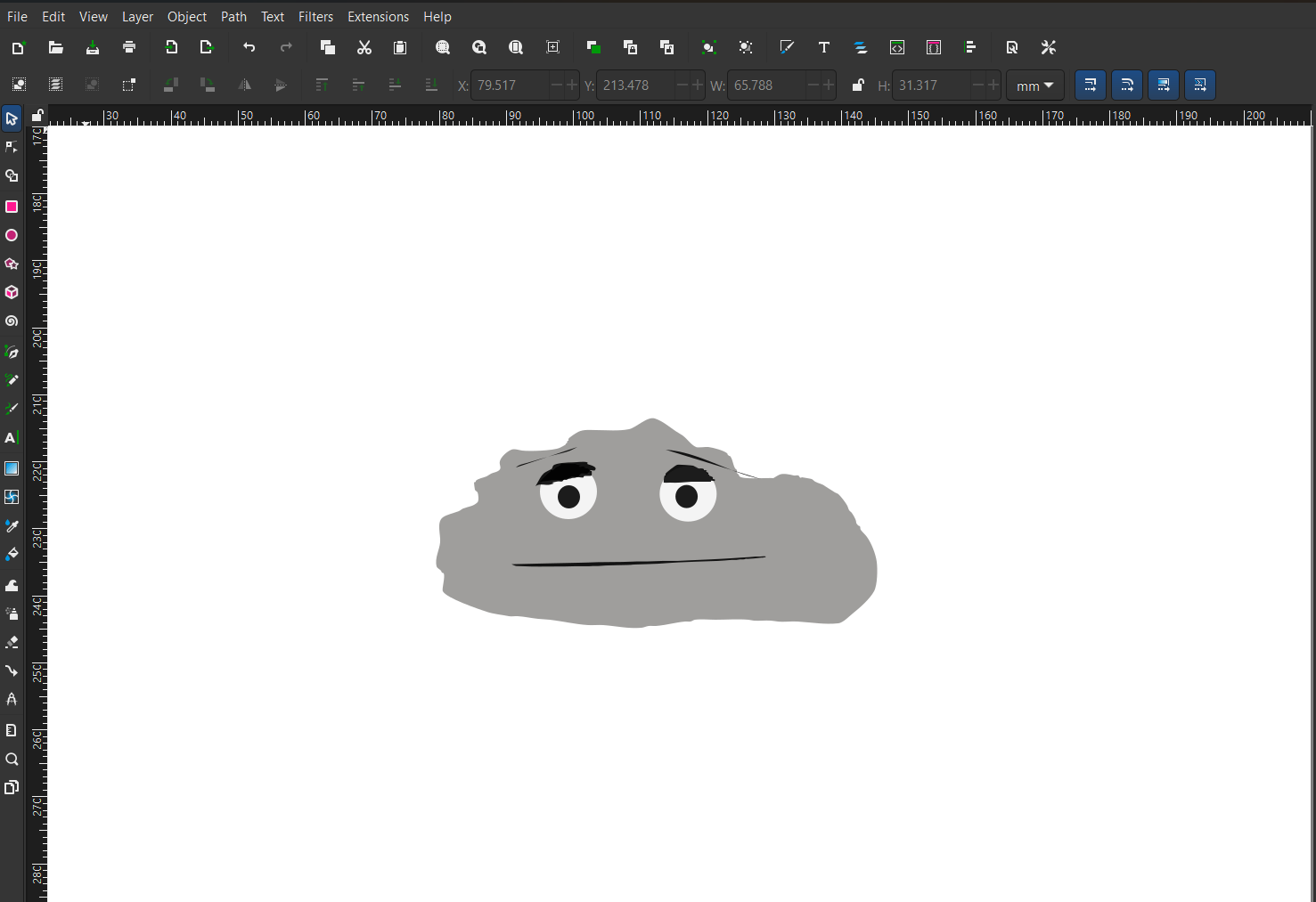
With pencil tool I made the rest of the factions
3D modeling
In this part I will use 2 different softwares for 3D design so I can start modeling the pieces of my final project.
SolidWorks
Fab Academy offers 3D CAD software licenses like SolidWorks.
I've never used SolidWorks before, I learn how to design with Catia so this will be new for me.
SolidWorks is very powerful software, and it's used a lot in industry. To start, we need to create a new sketch.
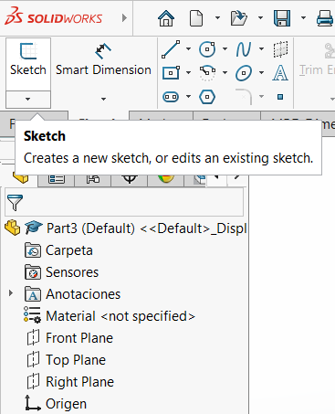
Once you have created a new sketch you must select a plane: x, y, z
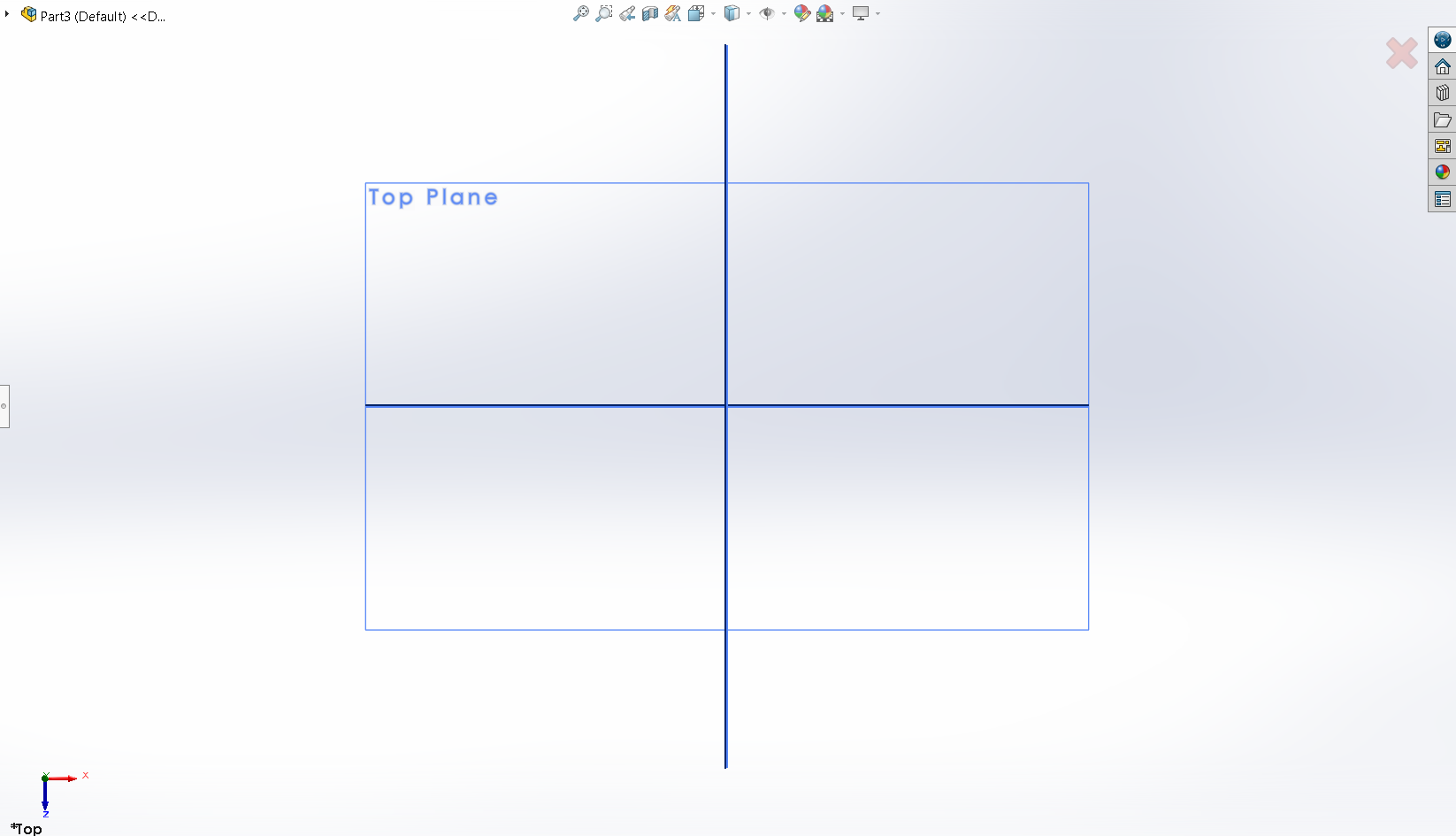
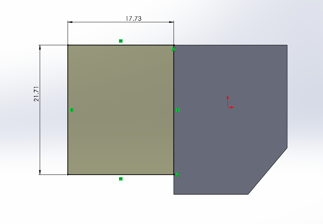
And with the tool “line” start drawing the piece you want to create.
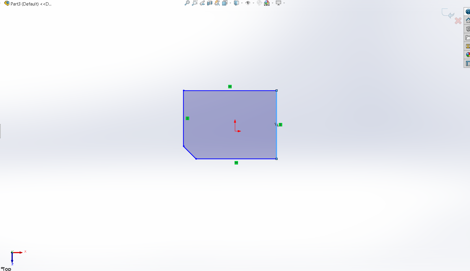
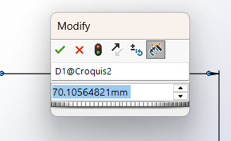
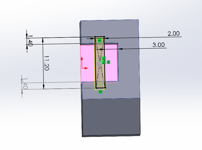
With the tool smart dimension, you can assign the value of the dimensions to the parts of the piece
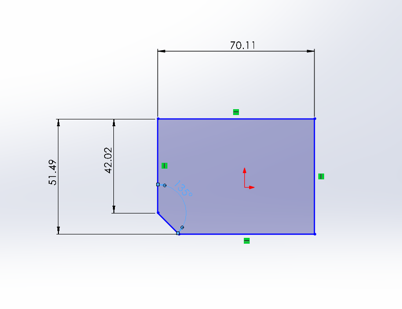
And double click on the measurements you can adjust it and give it a new value
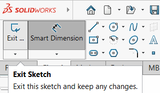
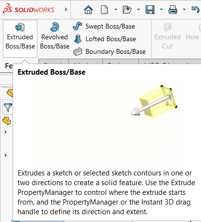
Now that we have our measurements correct, we exit the sketch and click on Extruded base
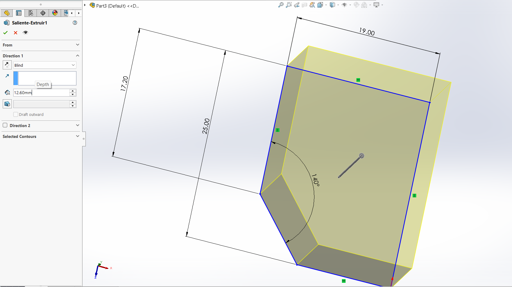
Now we have the first part of our design ready. Next, we need to make a rectangle and give it a 2.6mm extrusion
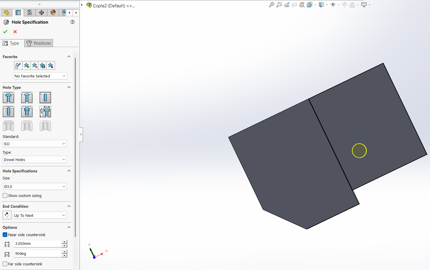
Then we need to place a hole on the new part so we can mount it with a M3 screw. We'll use the next tool to make the hole
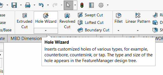
With this menu we can adjust the diameter and type of the hole.
Now with the tool extruded cut we'll make a cut on the piece as shown next.
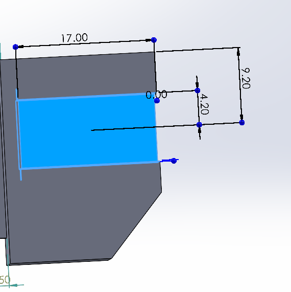
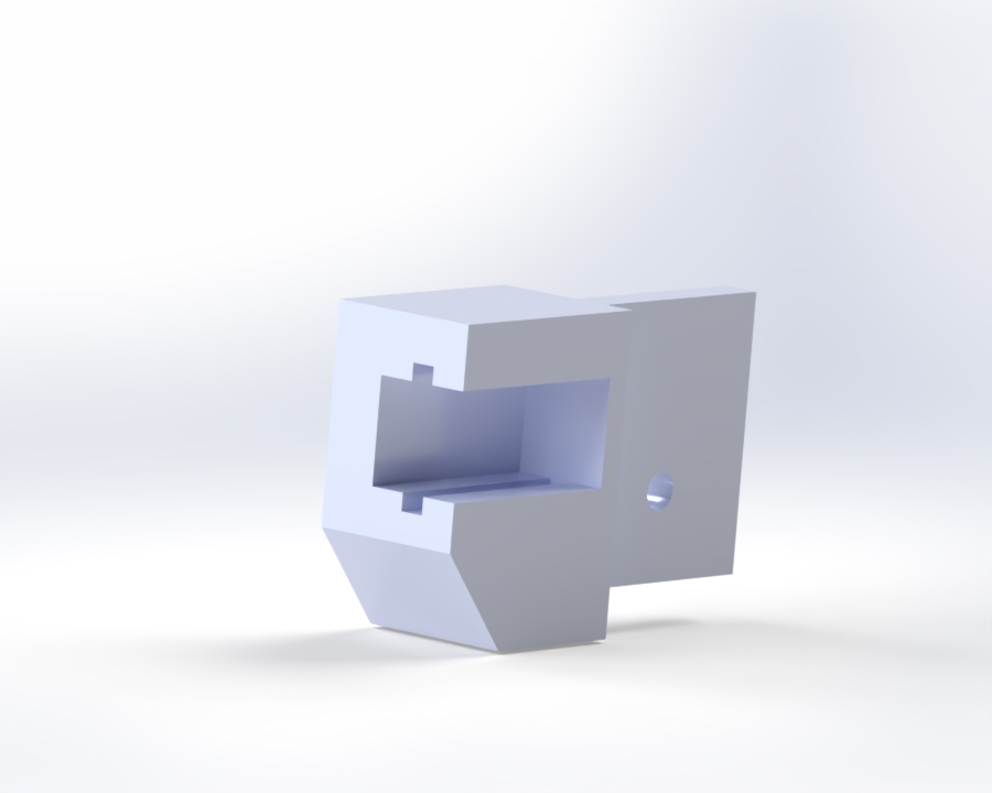
And now the firts piece is ready!
SolidWorks is not that different from Catia so if you're familiar with the software and the basics you won't have any problems using SolidWorks. In fact, the interface is more user friendly and easier to use.
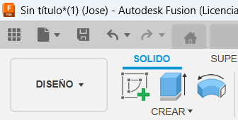
Fusion
I downloaded Fusion with my university credentials. Fusion is not that different from other 3D design software's so with the knowledge I acquired form SolidWorks and Catia I was able to easily use the software and design the base of my final project
I started as by opening a new project in Fusion
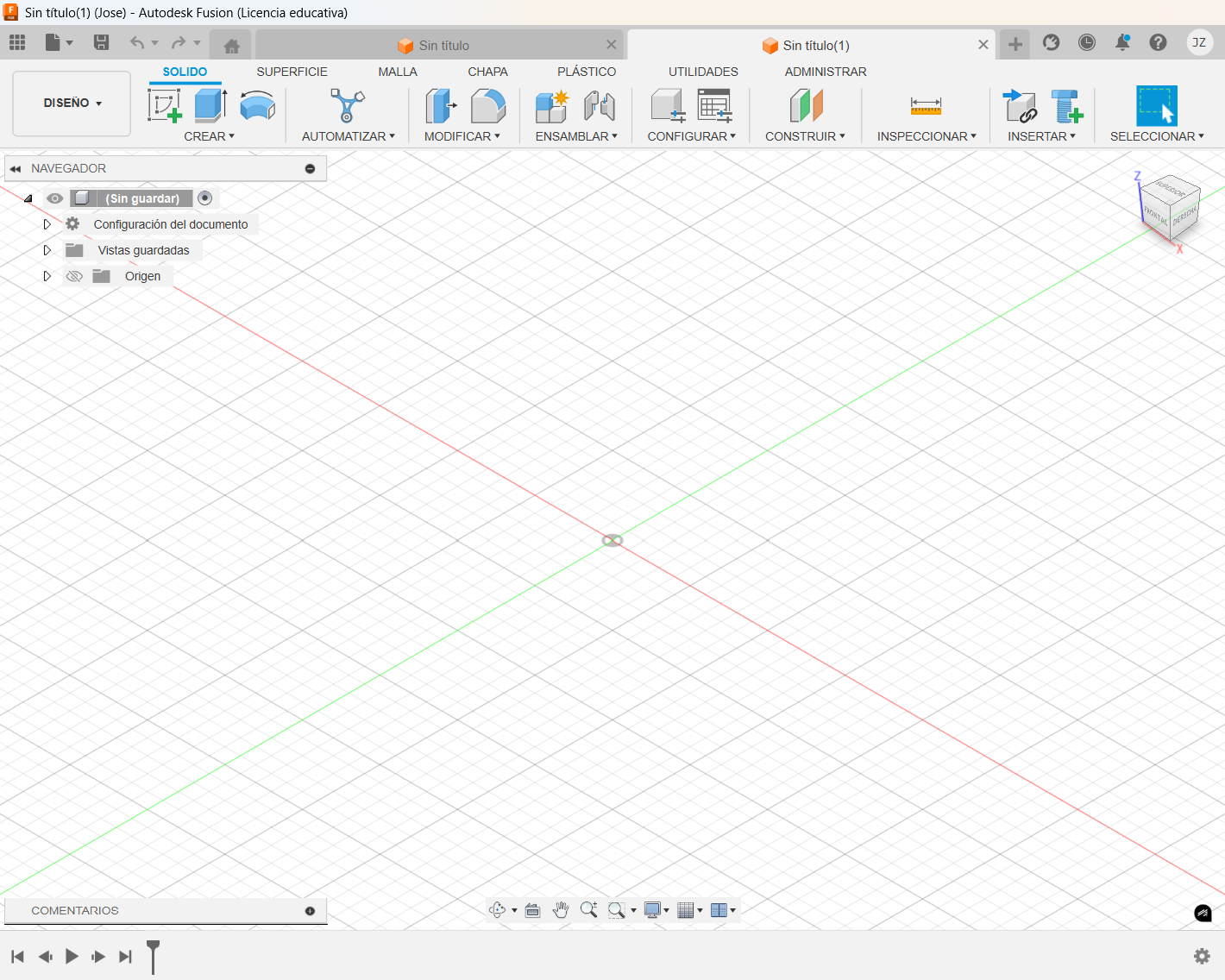
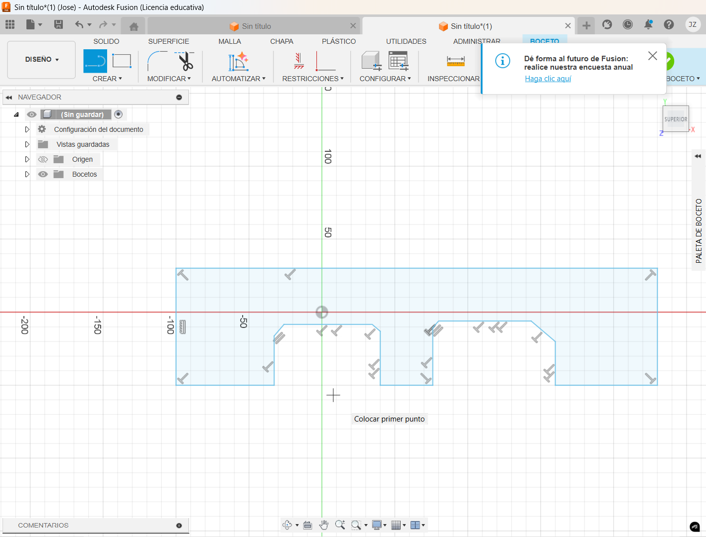
Create a new sketch
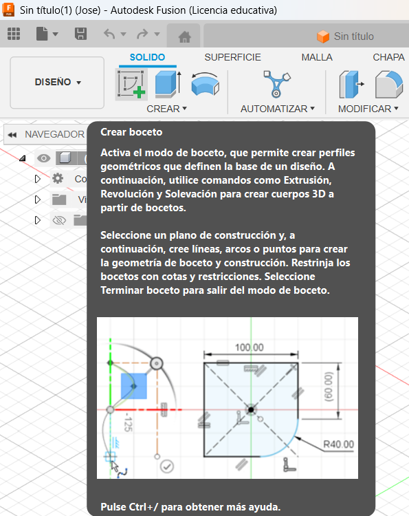
Locate the line tool and start the drawing
Once I had the drawing, I proceed to give it the correct dimensions. Right click on the line to measure and select the measurement option.
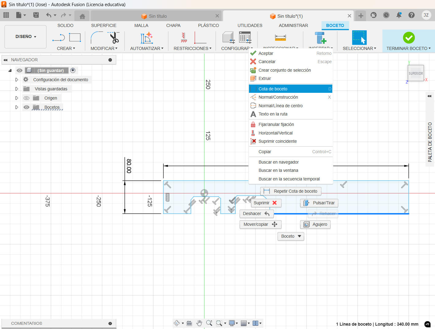
Once applied the measurement with double click you can adjust the distance or angle between each line.
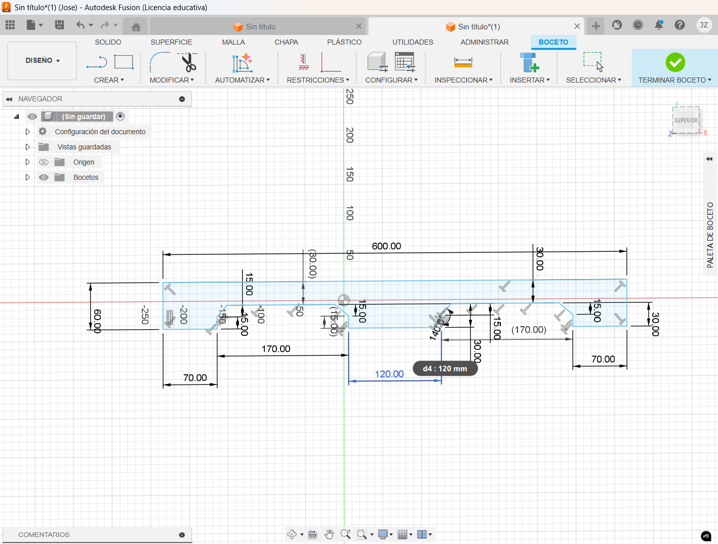
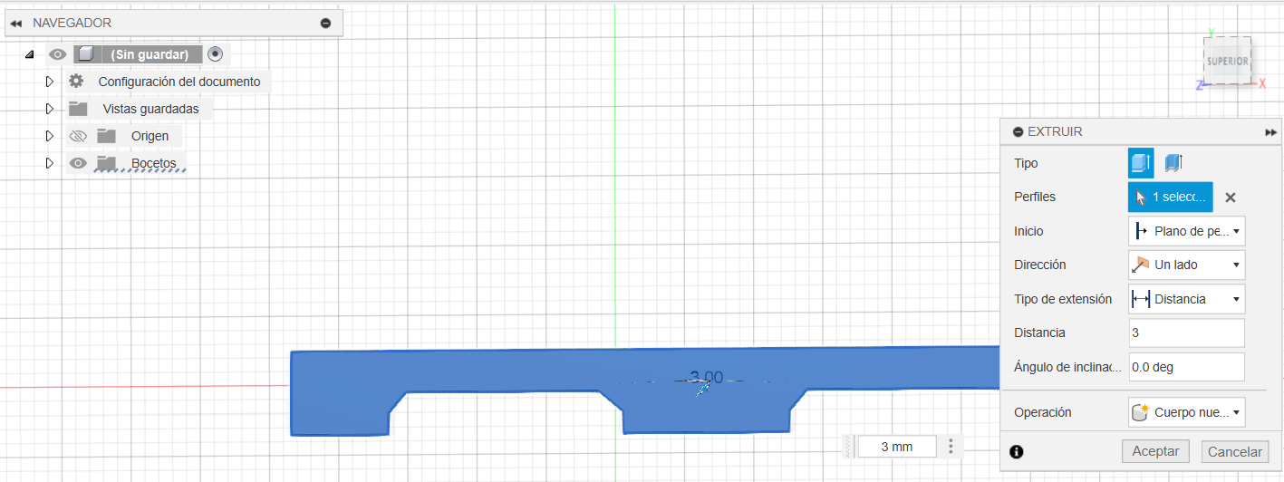
Once the correct measurements have been applied, we can extrude the piece.
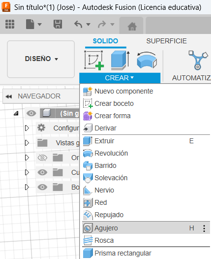
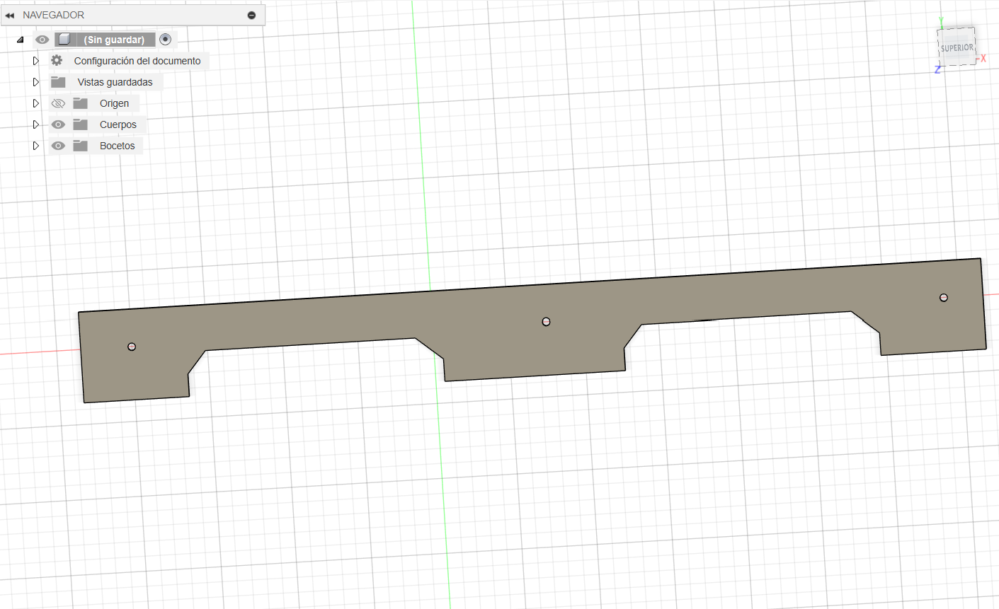
I need to make some holes for screws, so I used the hole tool. It's located on the solid toolbox in the create section.
Then locate where to put the hole in the sketch. The next menu will appear, in there I changed the diameter of the hole as well as the type that will be used.
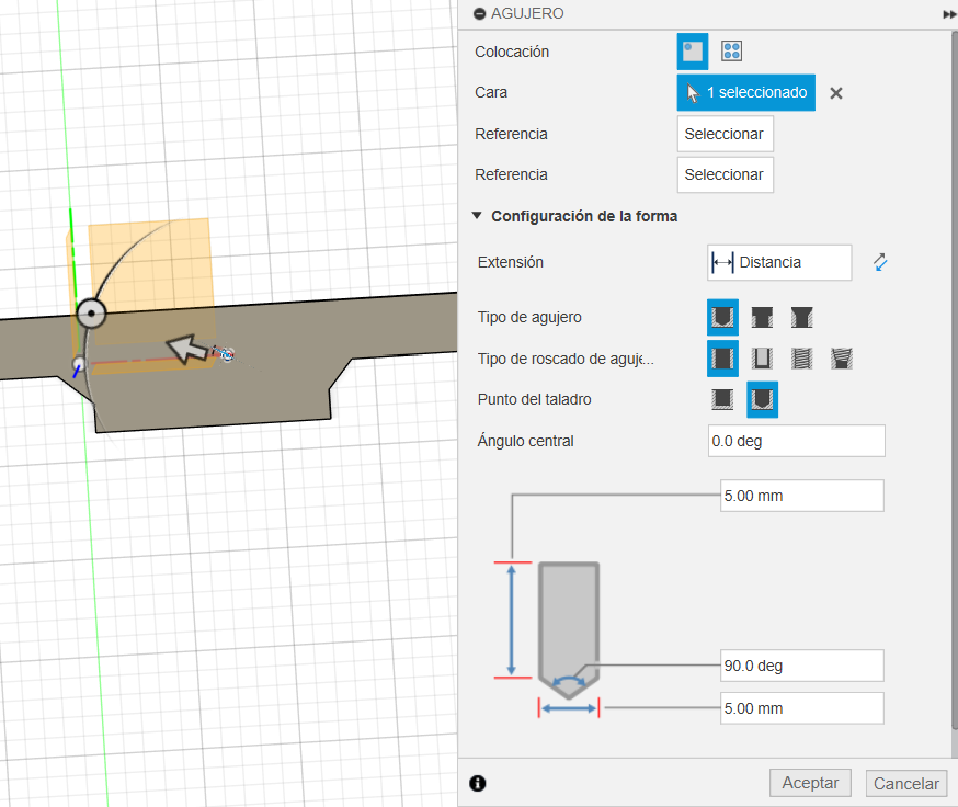
And now the piece is complete!