Week 9. Input devices
But first
Second of all
The xiao rp2040 can be either programed with arduino language or micropython, I decided to try both but starting with micropython.
To know how to get started with this microcontroller you con go straight to the Xiao rp2040 website There you will find
everything you need about this micro controller and some other of the same brand.
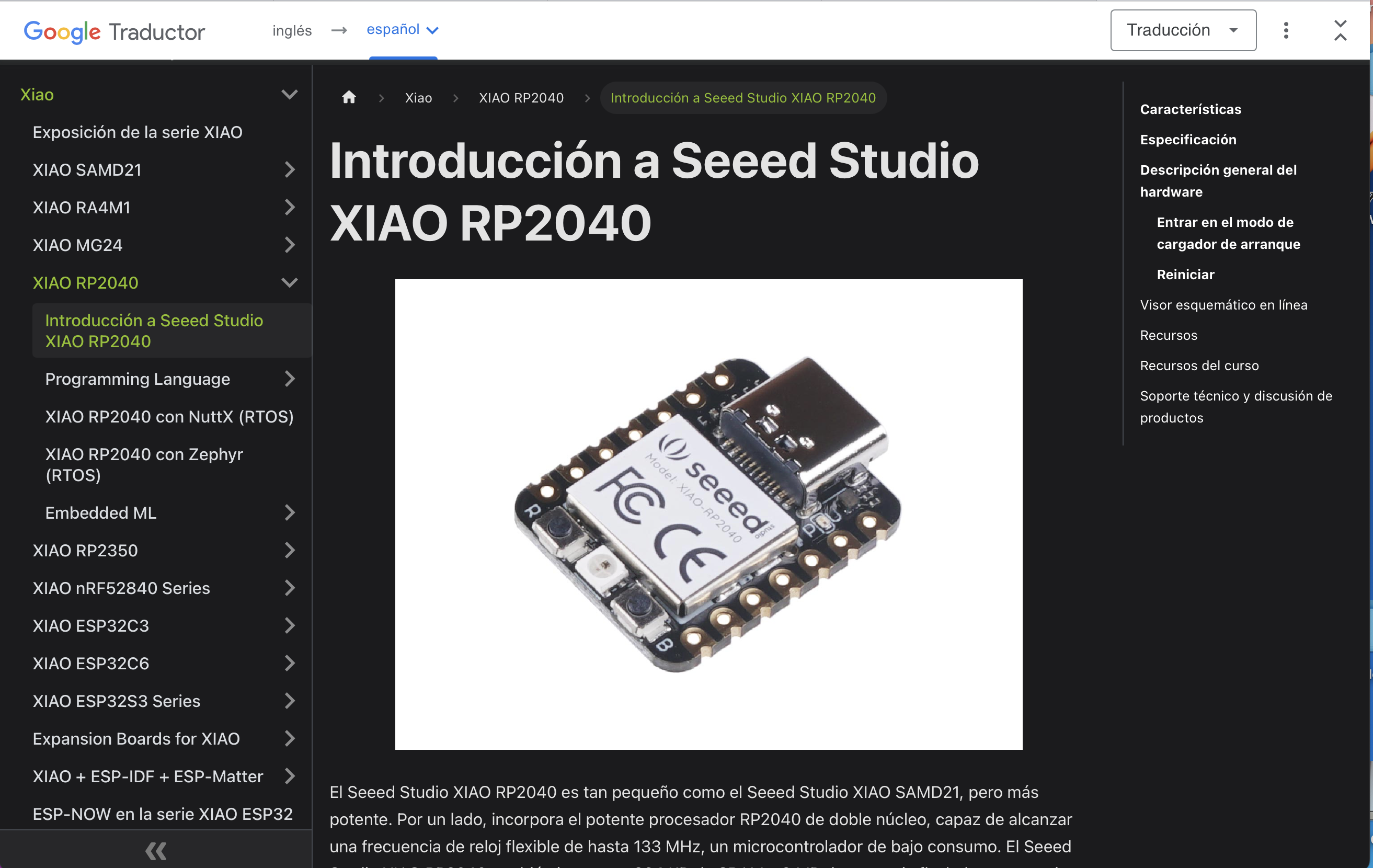
It looks like this, as you can see on the left side menu there are model of microcontrollers, and the rp2040 is on green, just bellow the selection there is a "Programming Language" button, click on it and it will display 3 options of languages, within those languages are arduino and micropython, I just clicked on micropython and the steps t follow will display on the center of the website. Just follow it.
Input means sensors, any kind of sensors, I made a ultrasonic distance sensor and and a joy stick.
It is important to say that this devices are sensors because they will tell the micro controller what's going on on the real world. This devices will also let us introduce
data to our micro controller. NOTE, this devices will always be written on the code with "INPUT" on the pin declaration.
HC-SR04 Ultrasonic distance sensor

This sensor uses sound and time to measure distances, one of the cylinders (trigger) sends a sound wave, the sound wave travels until it collides with something on it's way, then, the sounds goes back to the second cylinder (echo) and the measurement takes into account the sound speed and the time it took to the sound to travel from the trigger, to the object and back to the echo. So you have to do some maths to get the result in cm, mm, in or ft. So here is the PINOUT:
Pin out
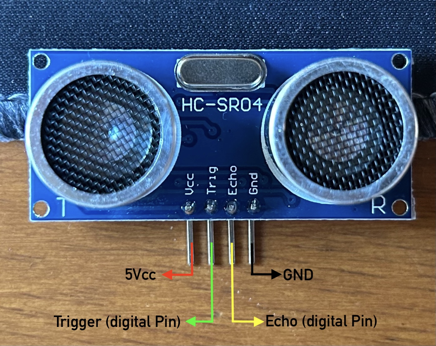
There is the same sensor with just 3 pines, so check twice which one are you using
Operation information
Here is the most relevant information about the dataset:
| Parameter | Value |
| Working voltage | DC 5V |
| Working current | 15mA |
| Working frequency | 40Hz |
| Max range | 4m |
| Min range | 2cm |
| Measuring angle | 15º |
| Trigger input signal | 10uS TTL pulse |
| Echo Output signal | Input TTL lever signal and the range in proportion |
| Dimension | 45*20*15mm |
NOTE I took the information from this data sheet where you can also se more Datasheet
Programming it
Now, I consider important to say that I tried connecting the sensor to my xiao rp2040 and to a Arduino UNO, because this kind of sensors work better with arduino. As I'm using the xiao rp2040 with micropython I had to look for a way of making the sensor work with this program but I figured out it's almost the same as programming it with arduino But here I had an advantage, I looked on the one who teaches you anything YouTube for a way of doing it and I found Gold, a video and a library that made me everything easy. So...
Ultrasonic distance sensor with micropython
First I looked this video , it is a tutorial of how to use this sensor with micropython. This video took me to to this library , this is basically the same as in arduino but you just have to install it in your microcontroller and call it in your code.
How to install a library on your micro controller using Thonny
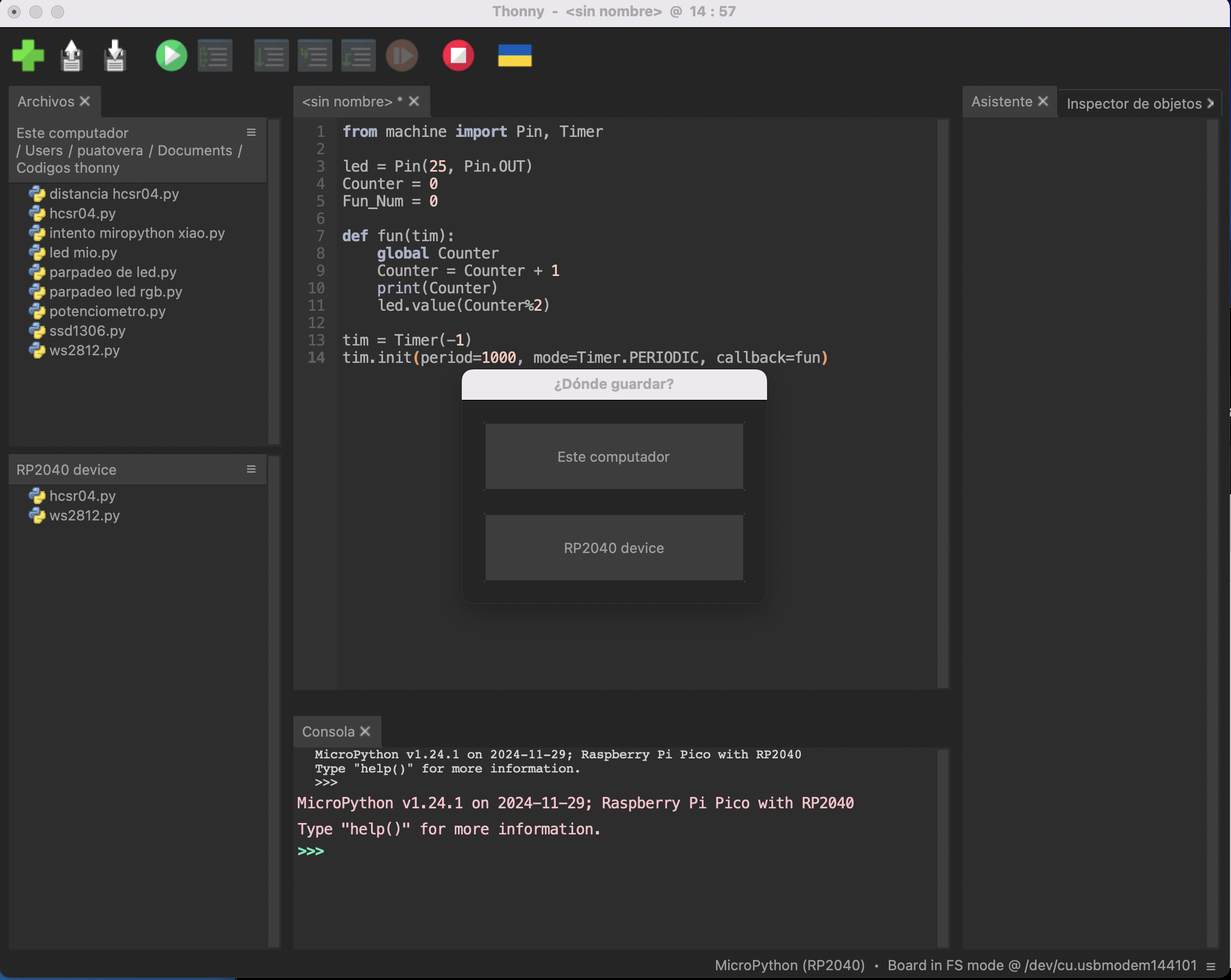
Open the .py file on Thonny like if you were going to writ a code, but just open it, don't modify it. One opened connect your microcontroller to the pc and make sure

This legend appears on the consol of Thonny, that means the microcontroller is connected to the interpreter. Now click on "saves as" immediately the interpreter will ask you ¿Where do you want to save the file? in your computer on in the rp2040 device?. You have to click on the "rp2040 device" option.
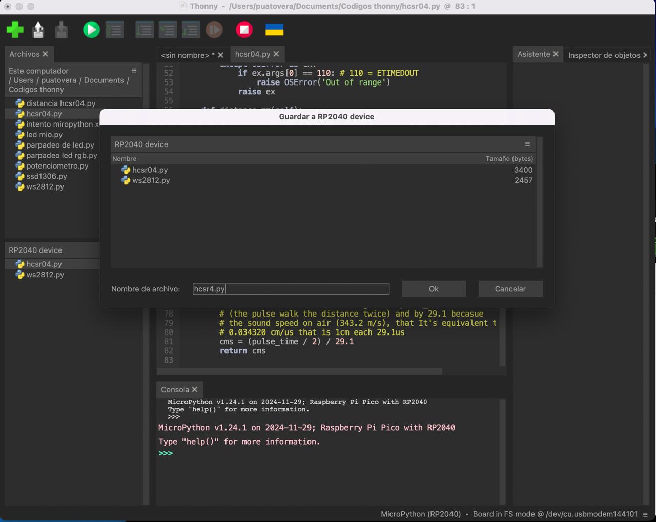
Just a help image. A new window will appear once clicked on the device option. Here you will have to give a name to the library, be careful with the name you write because this will be the one you will need to call on your program, so in my case I just named it as it was. "HCSR04.py". Don't forget to add the .py extension. Then click on ok and that's it, you have your library on your microcontroller.
Now, if you go to the upper menu of Thonny on view and activate the option "files" you will see the files on the micro controller.
Use the library
We have the library installed, we just have to connect the sensor to the plate like in the pinout image, remember the "trigger" and "echo" pin go to a digital pin. Connect the micro to the pc and make sure Thonny reads it. Then we can make our code.
from hcsr04 import HCSR04
import utime

while True:
  sensor = HCSR04(trigger_pin=28, echo_pin=29, echo_timeout_us=1000000)
  distance = sensor.distance_cm()
  print("Distance:", distance, "cm")
  utime.sleep(1)
Yep, that's all we would need using the library. Just so you know, the first value when calling the library is the pin of the trigger pin, the second one is the echo pin, and the last one is the time that echo will hear in microseconds. You can read the commentaries of the library for more information.
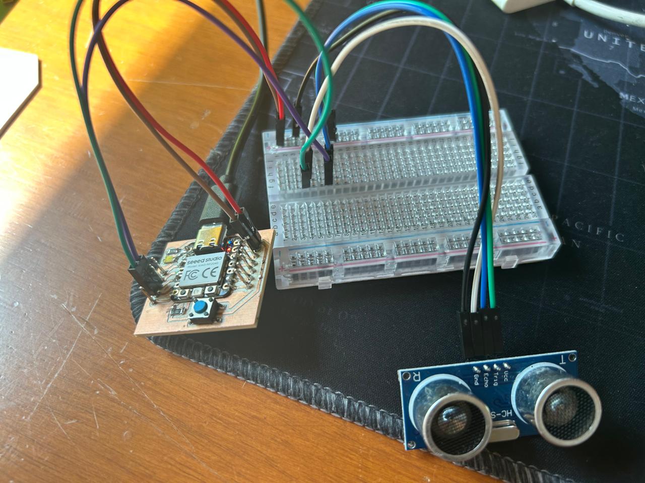
Note, I had to use a protoboard because the sensor has plugs, my plate has also plugs, and I don't have jack wires
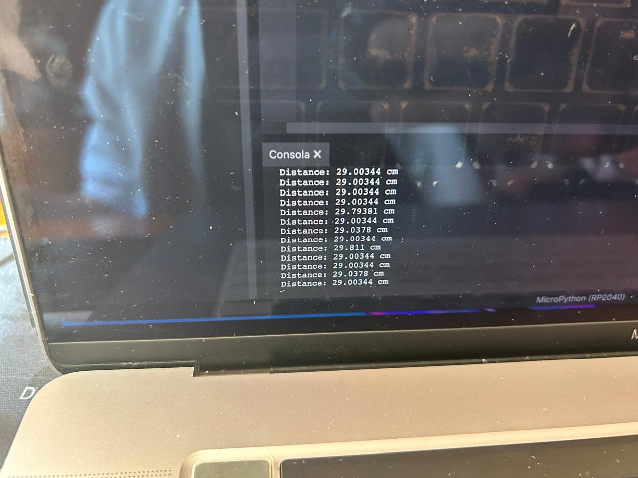
Measuring
Here is a demonstration of the code and the sensor works.
The files
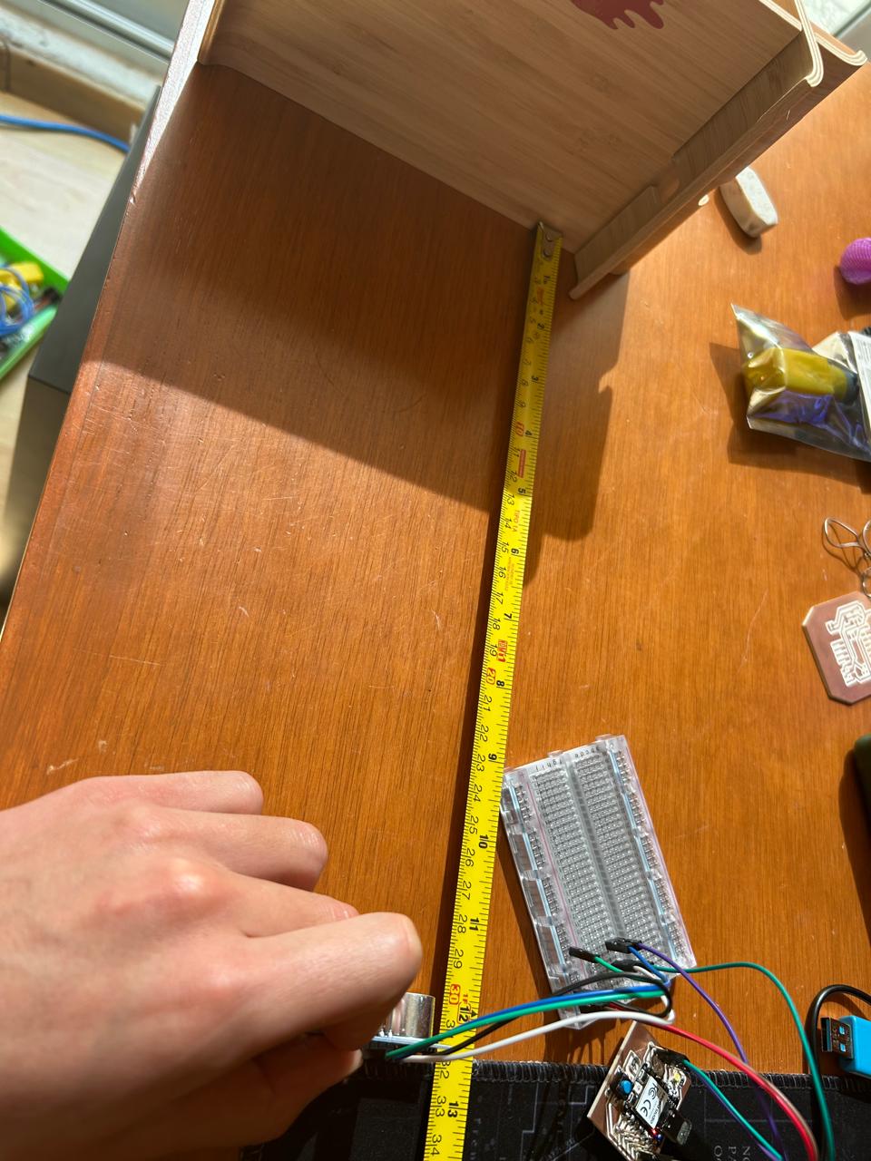
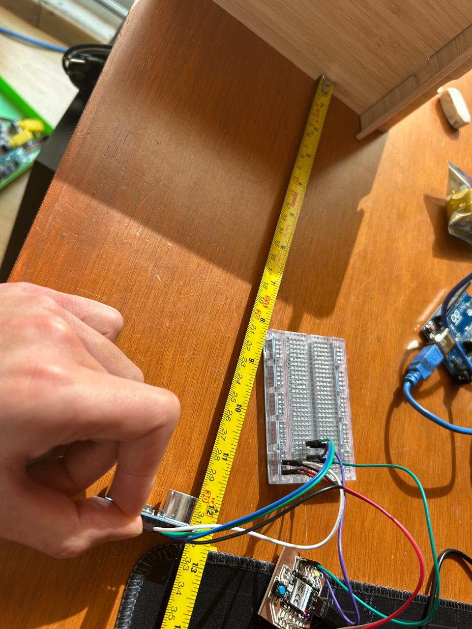
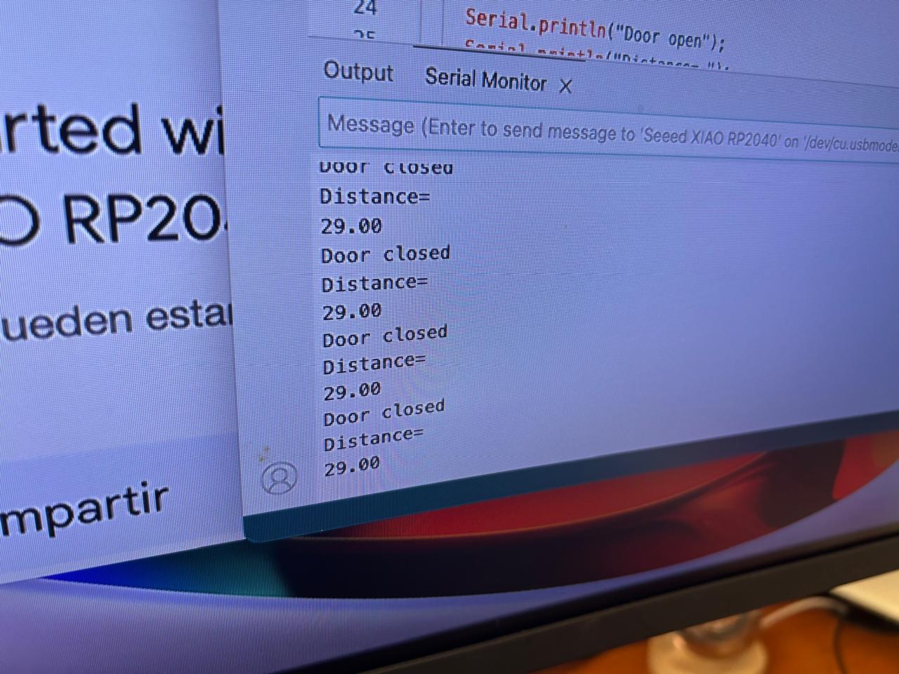
Checking the real measurements
The distance on the previous videos seems to be real, but how real is it, so I just measured it with a ruler. See it a judge your self. Just look how the end of the cylinders are on 30 cm and the code displays 29.00034 cm
Now with arduino
Arduino is almost the same thing, there is a tutorial on the
Xiao rp2040 website
that you can follow to run and program your rp 2040 with arduino.
The connections are the same on the arduino but the thing that do changes with arduino is the code, here we have to make from cero.
IMPORTANT NOTE, arduino is a little pickier than Thonny so, once everything is installed, you have to disconnect and connect again the micro controller to he pc, and while you are connecting it you have to keep pushed the "B" button of the xaio rp2040 a new disk will appear as if you connected a USB, then you can send the code to the micro controller and it will run, now on you can just connect the micro controller, select it on the arduino ide and run the programs.
Let's see the code
int trigger_pin = 6;
int echo_pin = 7;
float distance;

void setup()
{
  Serial.begin(9600);
  pinMode(trigger_pin, OUTPUT);
  pinMode(echo_pin,INPUT);
}

void loop()
{
  digitalWrite(trigger_pin, HIGH);
  delayMicroseconds(10);
  digitalWrite(trigger_pin, LOW);
  double time = pulseIn(echo_pin, HIGH);
  distance = (0.034 * time) /2;

  Serial.println("Distance= ");
  Serial.println(distance);
  Serial.print("cm");
  delay(100);
}
How does it work?
Let me explain it, the working procedure of this sensor (in a few words) is, send a sound wave, wait for 1o microseconds and turn it off then, take the time detected on the echo receptor and do the following maths: time * by the speed of the sound on cm/s (0.034) and then divide it by 2 because you have to contemplate the distance form the trigger and the back to the echo. So the formula is this one: (time * 0.034)/2 this is the distance in cm
The file
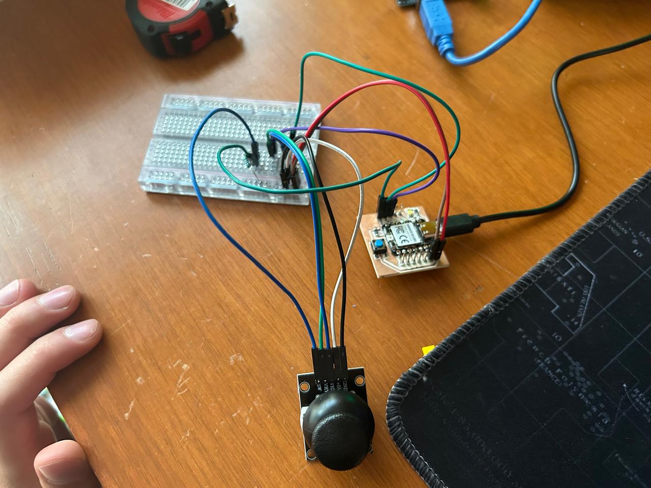
The Joystick
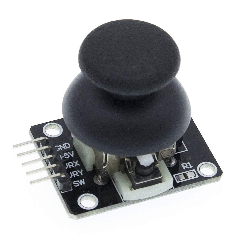
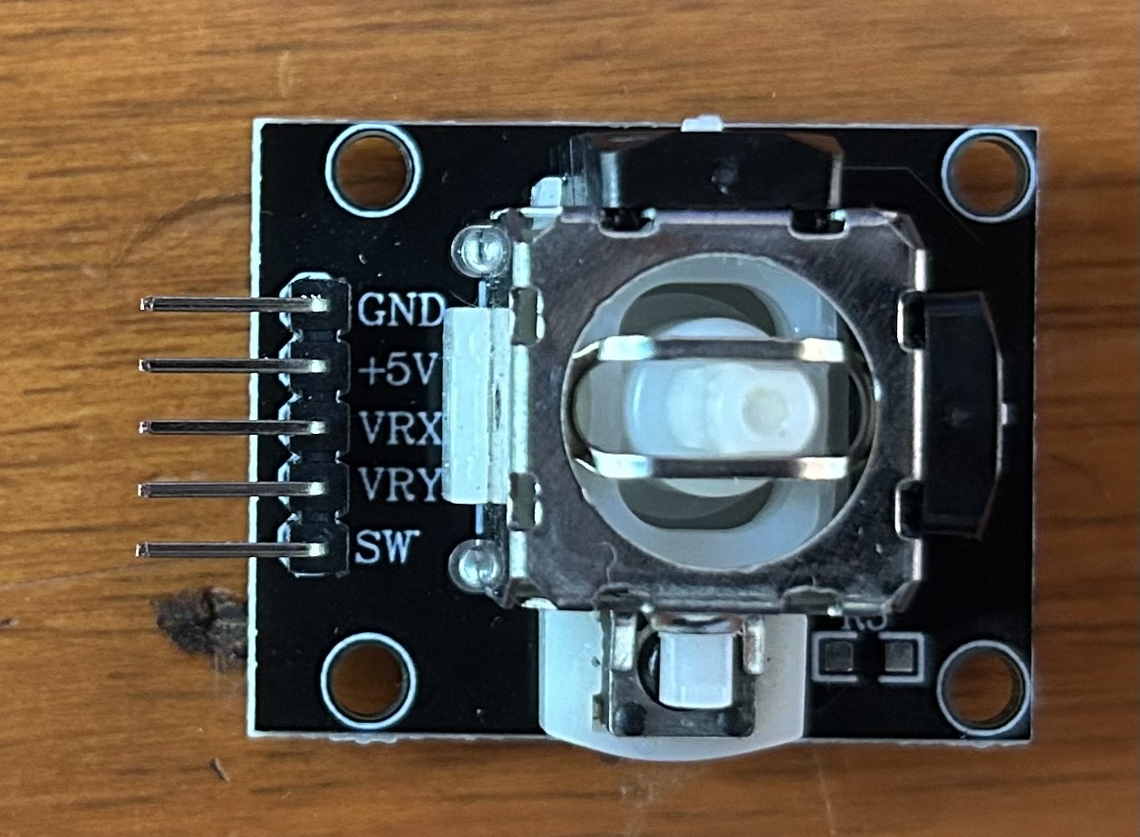
This joystick is the second sensor I used, it is basically 2 perpendicular but joined potentiometers, one for the movement on x axis and one for the movement on y axis, it also has a push button on pull up resistor. So this module has 5 pins
Pin out
-
Vcc
Input voltage -
GND
Output GND -
VRX
Output x axis -
VRY
Output y axis -
PW
Output pushbutton
IMPORTANT NOTE, as this joystick works with potentiometers, it's outputs will be analogic except for the push button, this will be digital.
Specifications
| Parameter | Value |
| Operating voltage | 5 V |
| Potentiometer resistor value | 10k |
| x and y axis output | Analogic |
| Push button output | Digital |
| Dimentions | 34x26x32 mm |
This information was recovered from the following Datasheet
How does it Work?
To use this module we also have to know how does this work, you see it as a cartesian plane, where your limits are 0 and 1023 (1023 is because we are converting voltages into binary values). Each potentiometer has it's 0 and it's 1023 so you will be working with coordinates. Let's take a look to the image of the datasheet:
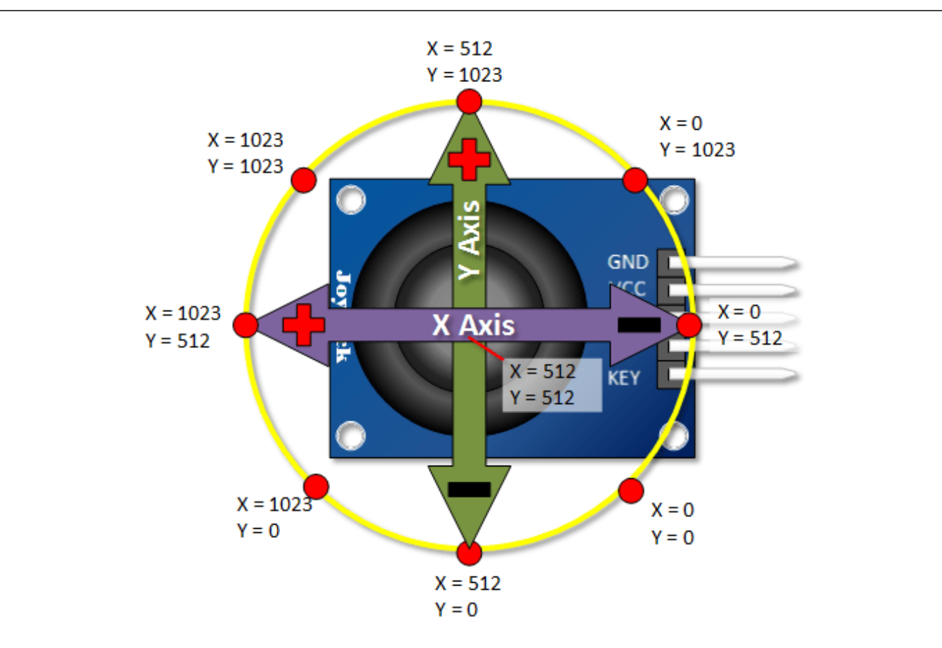
Yep, here yu can say the micro controller where the joystick is going. A quick example would be: if x axis and y axis are close to 512 or 512 don't do anything, but if x axis is 512 and y axis is 1023 go forward. And so on. Once again the push button is on PULL_UP resistor and I think that's the basic to configure it
The wiring
Just like on the datasheet but on a protoboard
Now let's program it with micropython
The code
import machine
import utime

xaxis = machine.ADC(3)
yaxis = machine.ADC(2)
push = machine.Pin(0, machine.Pin.IN, machine.Pin.PULL_UP)

while True:
  x = xaxis.read_u16()
  y = yaxis.read_u16()
  print("x: ", x)
  print("y: ", y)
  print(push.value())
  utime.sleep(.5)
As simple as this, this code just reads the values of the potentiometers an the push button and print them on the console.
Is important to mention that here in micropython, as the code just read in 16 bits the range for the potentiometers will be 0 - 65535.
And we are using a new function of machine "ADC" Analogic Digital Converter, so with this function you can write the number of the analogic pin on the micro controller instead of the general pin or the digital pin, also this will convert the microVolts values to a binary value with help of the .readu_16() command.
The file
The evidence
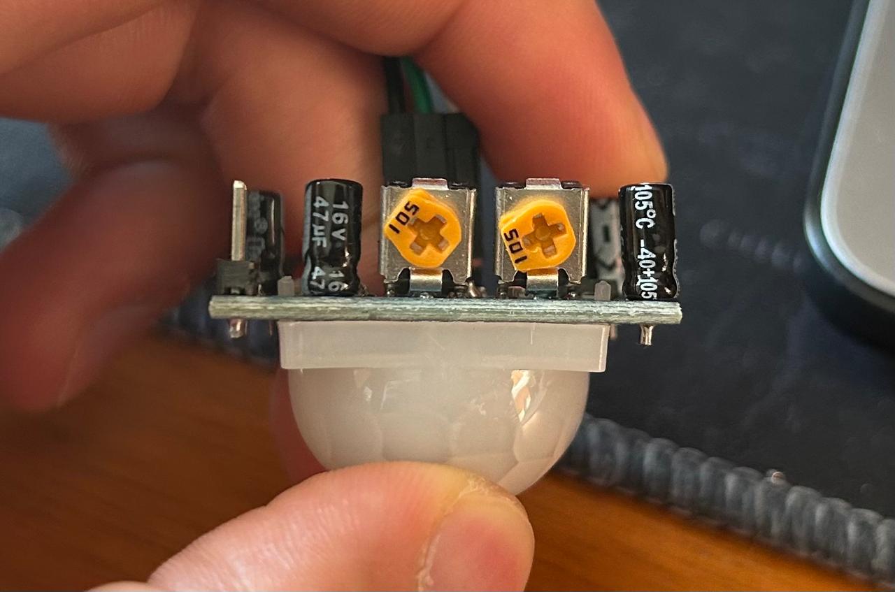
Infrared motion sensor (PIR/HC-SR501)
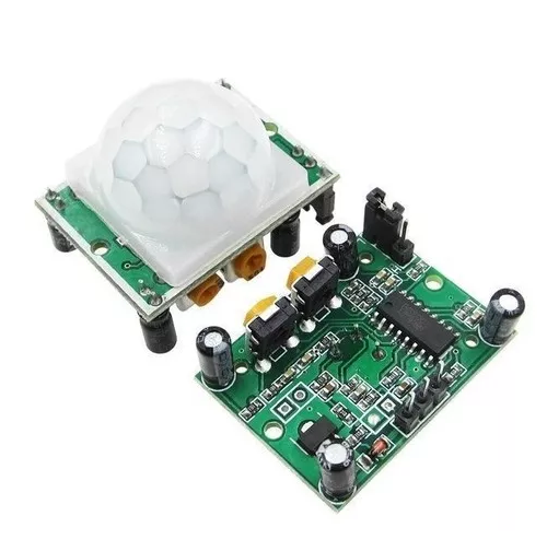
This sensor is what the name says, it detects movement, but specially the living creatures movement, because it works with infrared signals.
It is important no mention that this module has different modes of operation, and you can change the time and the range of response with the 2 potentiometer it has. It has only one output digital pin aaaaaaaand that's the quick "you need to know"
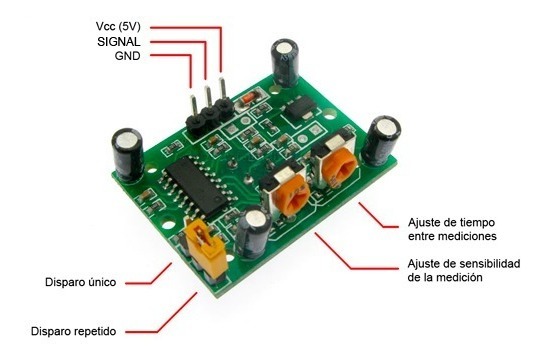
Remember the pinout, because on the plate there says nothing (excuse the spanish on the image but it is the perfect image ):
Pin out
Let's go with the specifications
| Parameter | Value |
| Operating voltage | 5 V |
| Consume current | less than a milliampere |
| Detection distance range | 3-7 m |
| Delay time of response | 3 sec - 5 min |
| Detection angle | 110º |
| Settings | Detection range potentiometer and response time potentiometer |
| Type of trigger output | Single shot and rettrigerable |
| Volt range output | 0-3.3 V |
| Initialization time | 1 min |
| Working temperature | 15º-70º |
| Dimentions | 3.2x2.4x1.8 cm |
You can see more on this manual
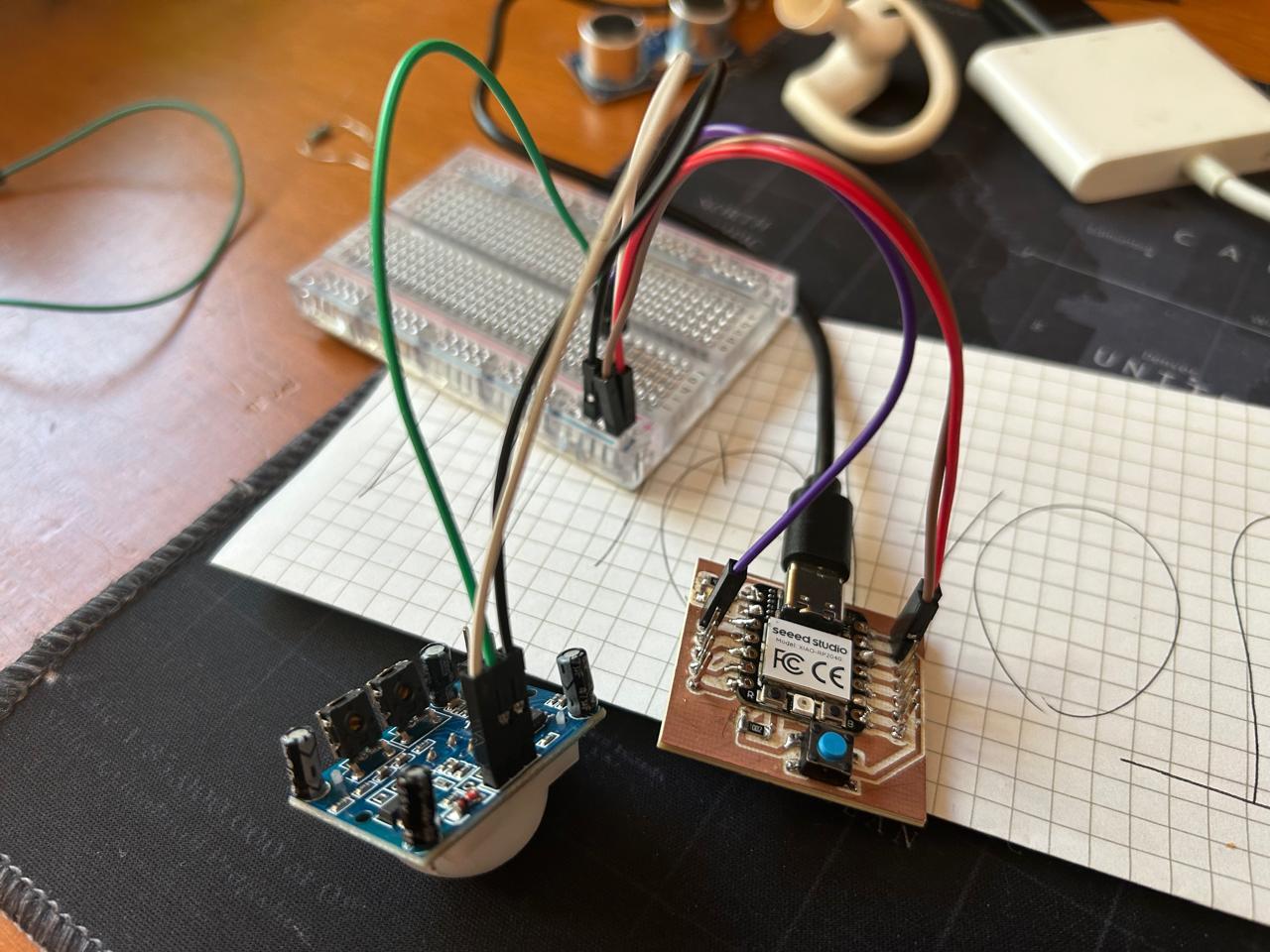
Configuring it
Alright, there are many ways to use this sensor, I'll go with the basic one, just connect the 3 main pins, set the lowest range (3m) and the fastest response (3) that's it, let's see the wiring and the potentiometer positions
The code
import machine
import utime

xaxis = machine.ADC(3)
yaxis = machine.ADC(2)
push = machine.Pin(0, machine.Pin.IN, machine.Pin.PULL_UP)

while True:
  x = xaxis.read_u16()
  y = yaxis.read_u16()
  print("x: ", x)
  print("y: ", y)
  print(push.value())
  utime.sleep(.5)
The file
The evidence
Learning outcome
Always check the datasheets of the sensors you are using they will tell you how to use them, connect them, how much voltage they consume, how many current they need, the kind of output. Basically everything about the sensor or the input device.