Week 8. Electronics production
But first
No introduction
I will just go straight to the documentation, electronic production, I understood this as creating the circuits physically. For this we need,
our pcb already made on kicad.
If everything went ok on the design week, we should be able to go straight to the production.
KiCad
Setting exportation dimensions
Let's open our design on the PCB editor and prepare some exporting parameters.
On the up menu, there are 3 buttons with kind of a printer.
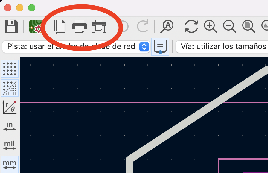
Yep, that image, the first button will open a window where we can edit the size of the page we want to export. Why is this? Because we have to export an image or SVG file of the tracks, holes and edges, and this parameters will help. Now, we have to measure the hole circuit to set the dimentions the file configuration, so, select the "Draw Orthogonal Dimentions" tool, and select th X and Y sizes of the edges of the circuit. It should be something like this
And set those measurements according to the following video:
NOTE, As the edge line is also important to export completely, I left a 1mm margin form the edges.
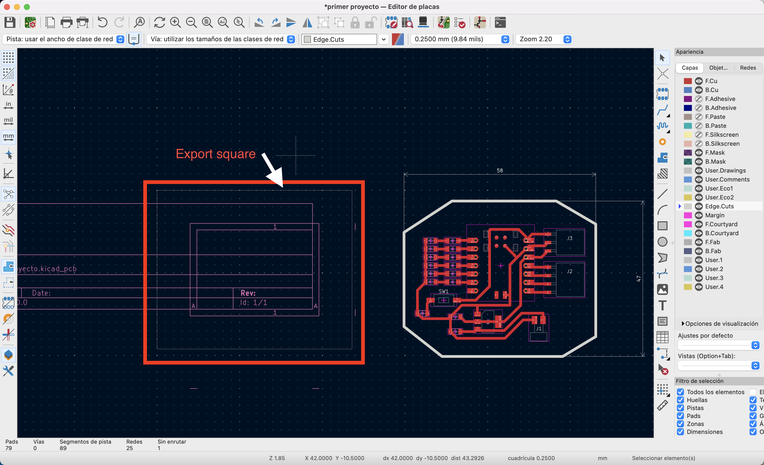
Click on the accept button and a square with the given dimentions will appear on the workspace this is the space that will be imported.
So we have to select everything and move into the square.
Just like on the image.
Export
Alright, we have the size of the file, and everything into the exporting square, time to export. Just follow the video.
In this window he have to make sure that the exporting file is SVG and just select the layers that we are using, in our case, F.Cu, edge.Cuts and user.1 Because it contains the tracks, edges and everything we could need.
Click on trace, and it will generate the amount of selected layers on SVG files. This files will be saved on the same folder as the project with the layers names.
This would be everything on KiCad.
Mods CE
Now we have to go to the wesite Mods CE This website creates the file that the machine reads to cut the cupper plate. Once in it looks something like this:

Creating a new sketch
We have to add/select the type of document we want to work with, for this, remember the "Roland/SRM-20-mill/mill2D PCB" and follow the next tutorial:
Right click anywhere on the website, the tiny blue square will appear, select, programs/open program and look the address I just wrote.
This will show you a flow chart with many things. Like in every program we have been using, we don't need to know everything on the flow chart except for the
important and basic things and those are the ones on the red circles of the following picture:
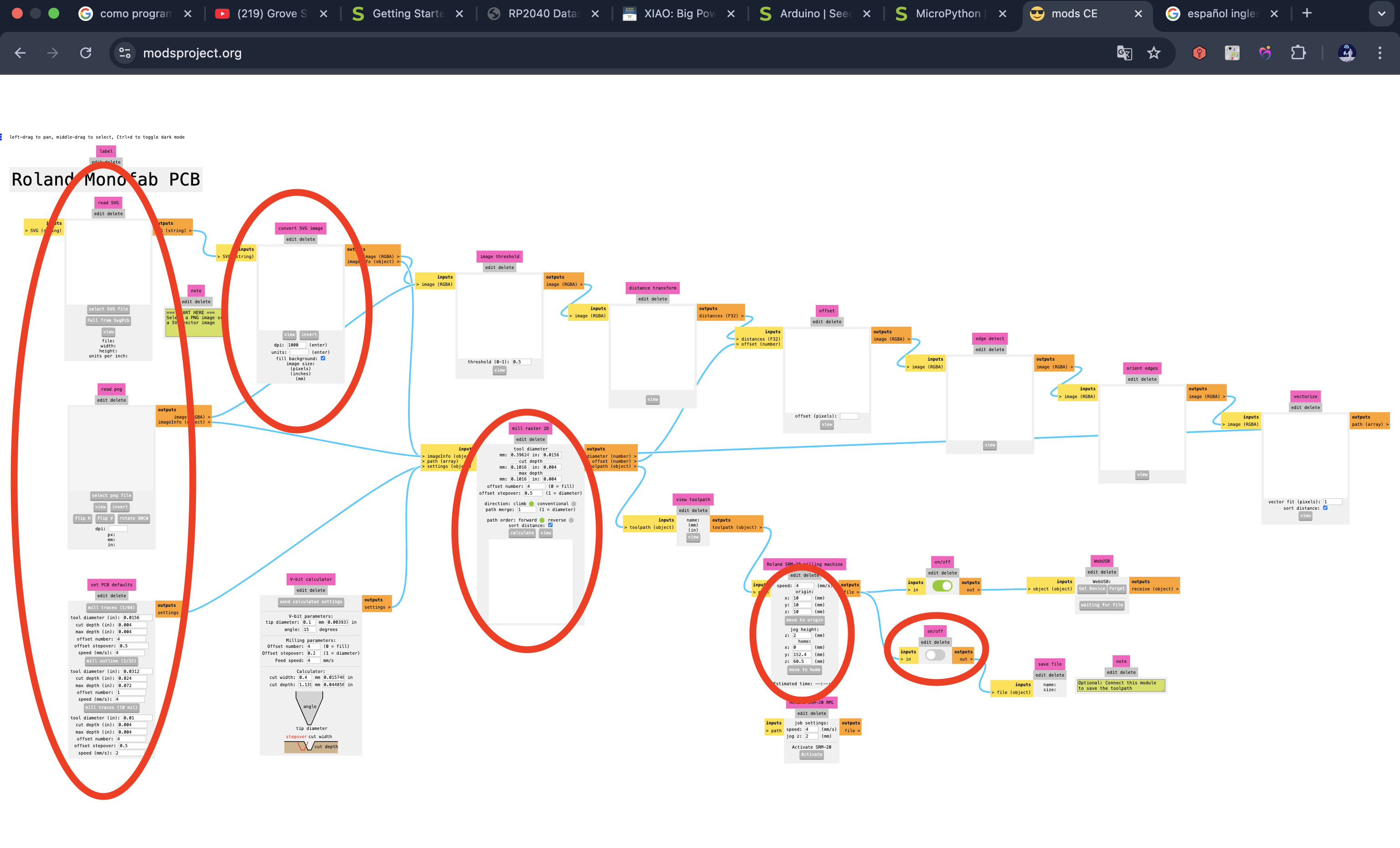
Let's go from up left to down right
The first rectangle
This one is to open the SVG documents just click on the button "Select SVG File" and look for your file on your documents.
NOTE, There are 2 points to take into account here, The first one: start with the holes, in case you have them, them you can go with the tracks and the last thing you have to cut is the edges.
The second thing
To take into account are the colors of the file, the will always cut the black color, and will ignore the white color. So, in case of the holes the infill has to be black. For the traces, the infill has to be black and for the edges the line of the edge has to be black.
Having said that we can go to the next block, "Image converter". The file will export in just two colors, but sometimes they are the opposite way, and we have to invert the colors, just click on the "invert" button just like on the following video:
That would be everything on this row
The block right under the "Select SVG File"
It is the same but for PNG, we are not using that one in this time. But the one right under this one, we are using that one.
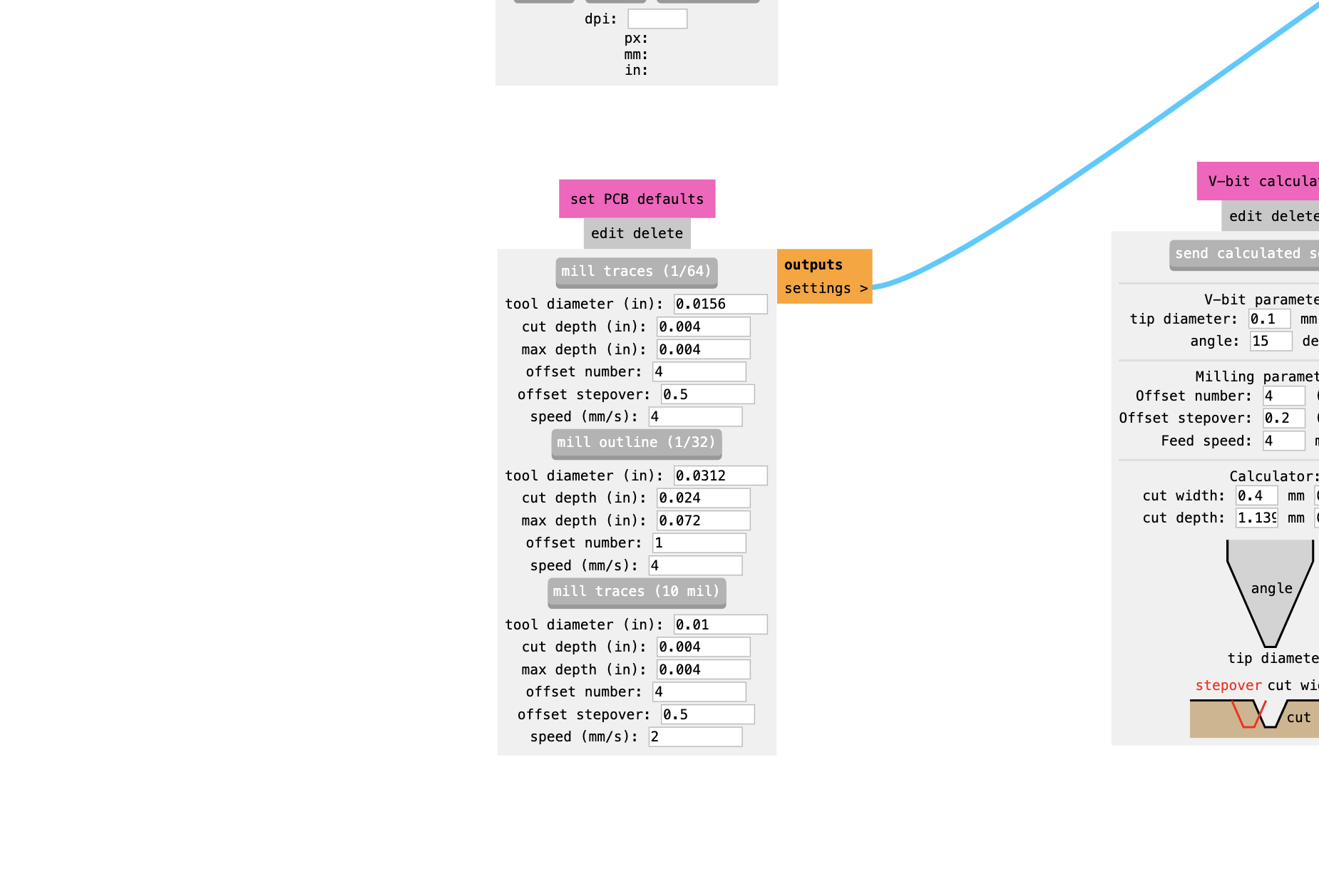
PCB defaults
This block set the dimentions of the tool we are using, but after explaining that, as you can see on the image it has like 3 sections:
-
mill traces (1/64)
The grey thing is a button if you click it the file will do traces, this means the tool will go just a little deep on the material, enough to cut the copper but not the entire plate. the tool diameter is in inches, and we had to convert from mm to in, however this kind of tools are usually standard so we can leave that number as it is, and the other ones have to stay as they are. -
mill outline (1/32)
This one will cut through the hole plate, in this case I do had to convert the mm to in becaus the drills we had where from 0.5mm and 1.2 mm. That's the only value we have to change -
mill traces (10 mill)
This one I didn't used it
We are done with the parameters of the tool and image, let's move to the
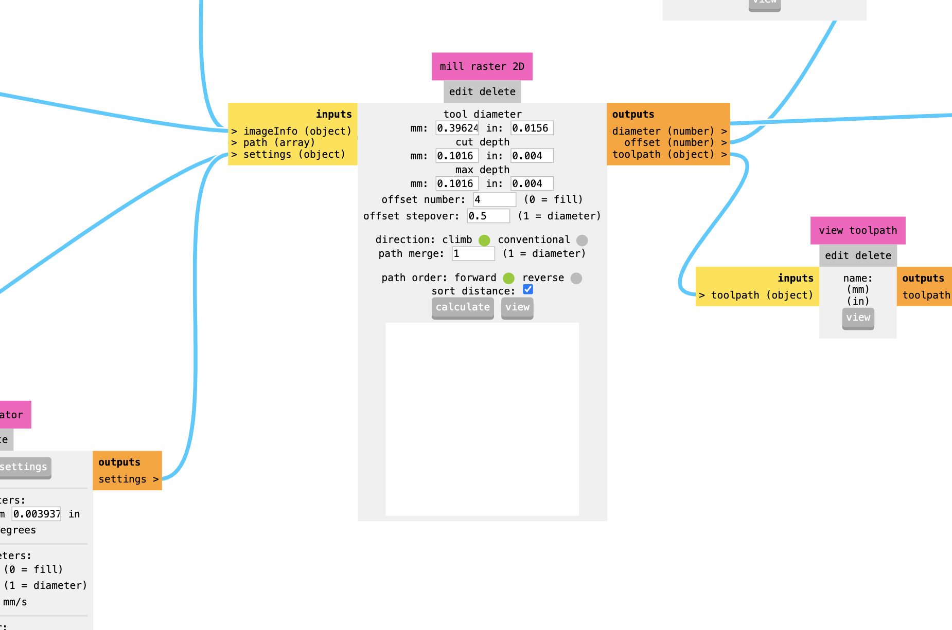
Central block
Here do not move the sizes of the tool, but here we can change the "offset number" and that's it, this means the number of offset traces that the machine will do, like the space from the traces to the rest of the copper and the other traces,
4 is a good number, and 0 is not cutting anything as I understood.
On this same block are the "Calculate" and "View" buttons, and we could push them
to create our file, and to preview it but there are two more that we have to look for.
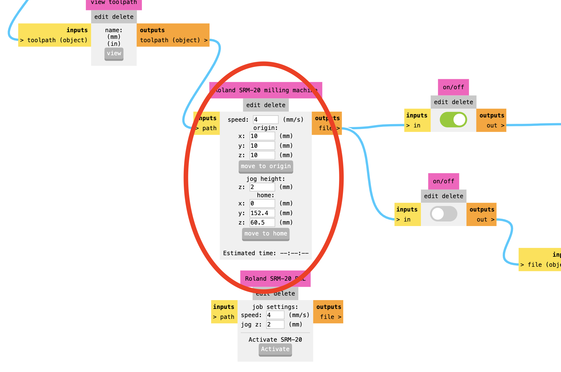
Origin and speed
The origin and the speed, the default parameters are not bad but we have to change them, starting with the origin, we have to place our origin on 0, 0, 0 so there is no issue when cutting and the machine starts on the same origin of the machine. Now the speed, 4 is a good number but it is better to put it between 0.8 and 2, the lowest for processes with very thin drills and 2 for processes with thicker drills.
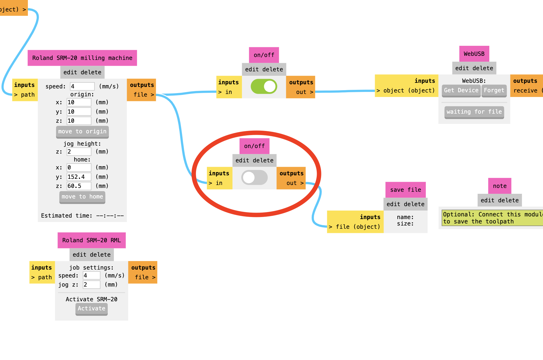
Save
The last block we have to check is the "save" block, you will turn that switch on and off depending on if you want to save the file or not.
Calculating the file
Just click on te button, check everything is as we need and click on calculate, a few seconds later a new page will automatically open to preview the process. Confirm it makes sense with what you want and there tou go.
You can turn on the save button and click once again on "calculate" to save the file, it will automatically save a file with the name "image SVG.rml" just change the name to the process name (holes, traces, edges) and hols on so I explain the machine part.
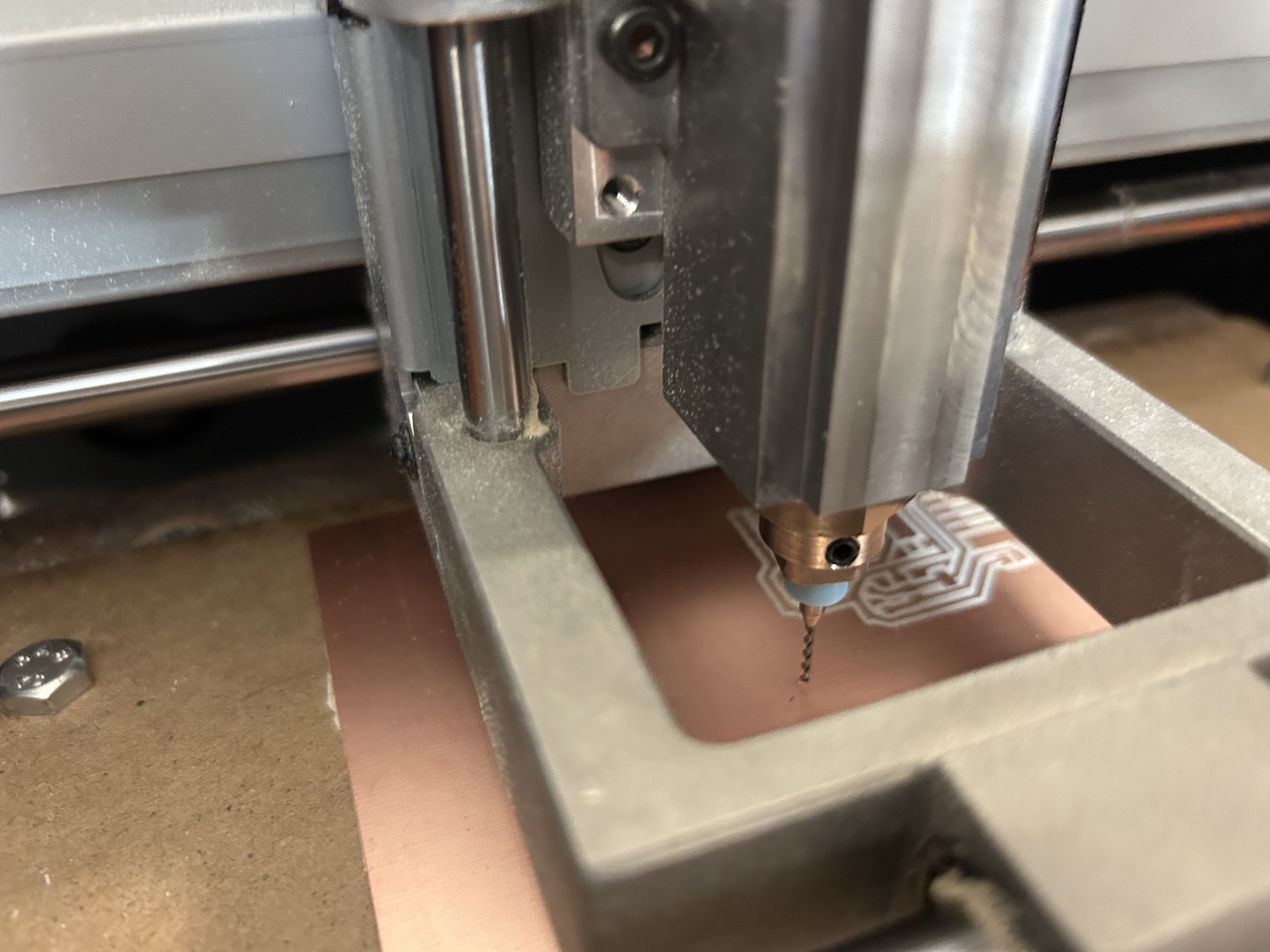
Let's go to the machine
The software and firmware
The machine we have here in Puebla is a mono fab RSM-20 and it is basically like a mini CNC
And before we start using the machine we have to download a program and a firmware
This is the firmware for the PC
This is the interface of the machine
So just we have to open the firmware folder and look for the "SETUP64.EXE" file, open it and the installer will open. It will ask you what you want to do (install, uninstall) and some question that has to be on USB. Then follow the process until it is installed. Once installed, we can open the second folder which has a single file, open it, install it, and a new ICON on your Desktop will open, it will have the image of the monofab.
NOTE, This program and firmware only work on windows, if you have mac like me, go get a windows.
NOTE, the program will only open as long as the machine is connected by USB to the computer, So before using the machine install the 2 programs, and while using it, keep it connected.
Fixing the plate to the bed
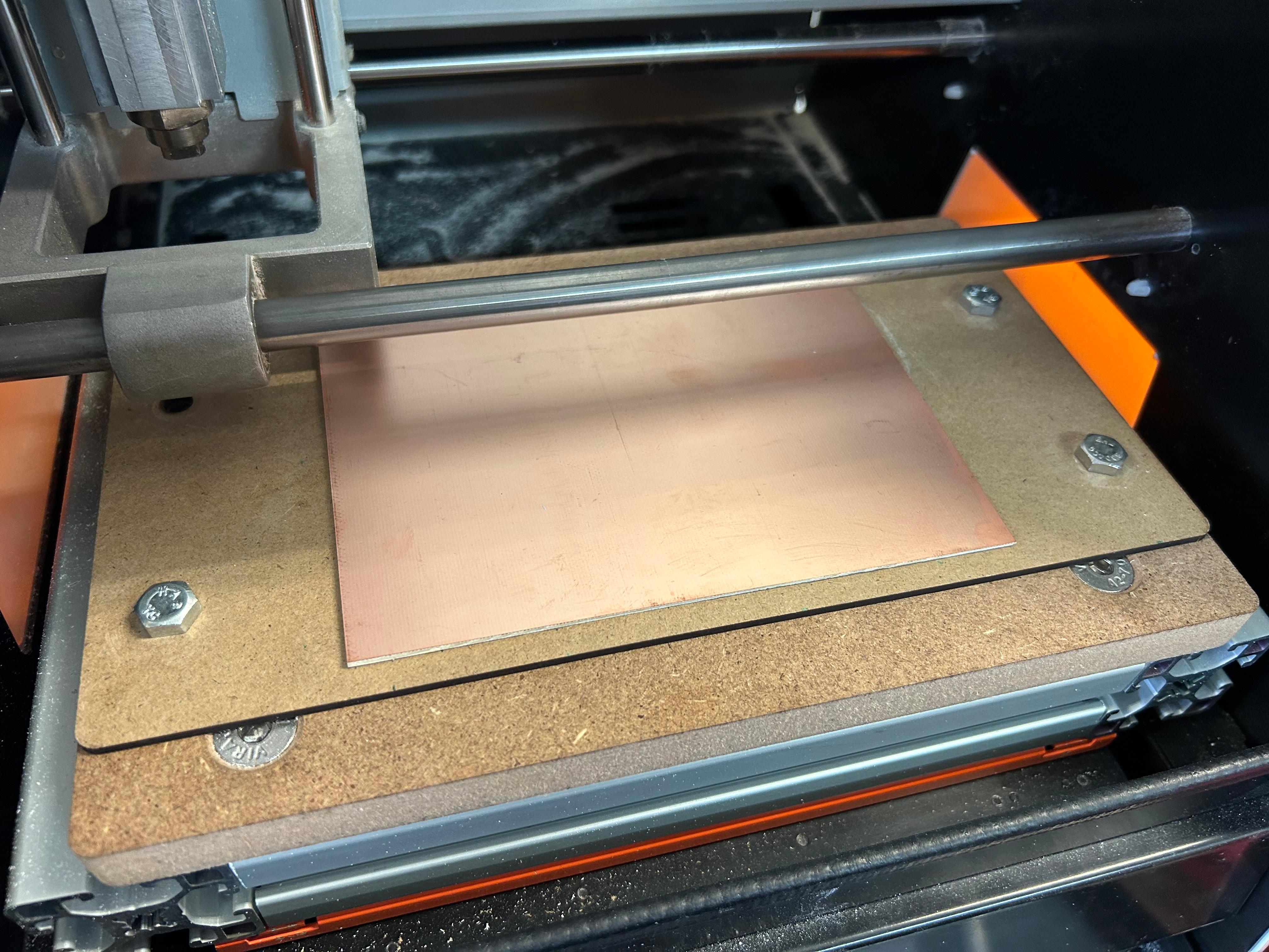
Before getting started with the machine process we have to make, a plate to fix the copper plate to the bed of the machine.
(In this case a classmate helped us cutting plates on MDF with the laser cut), make sure to fill the back side of the copper plate with double sided tape, and paste it on the MDF plate, them screw the MDF plate to the bed of the machine and we have fixed our plate.
It should be something like this:
Set the drill
Now we have our files and the machine connected before starting the cut we have to out the correct drill and set the machine origin.
As I mentioned the hole process will take different drills, the holes, depending on the diameter will use a tool, the traces will use a different tool, and the edges can use the same drill as the holes, or you can use a different one.
So the holes drill I used was a 0.5 diameter drill and it looks like this:
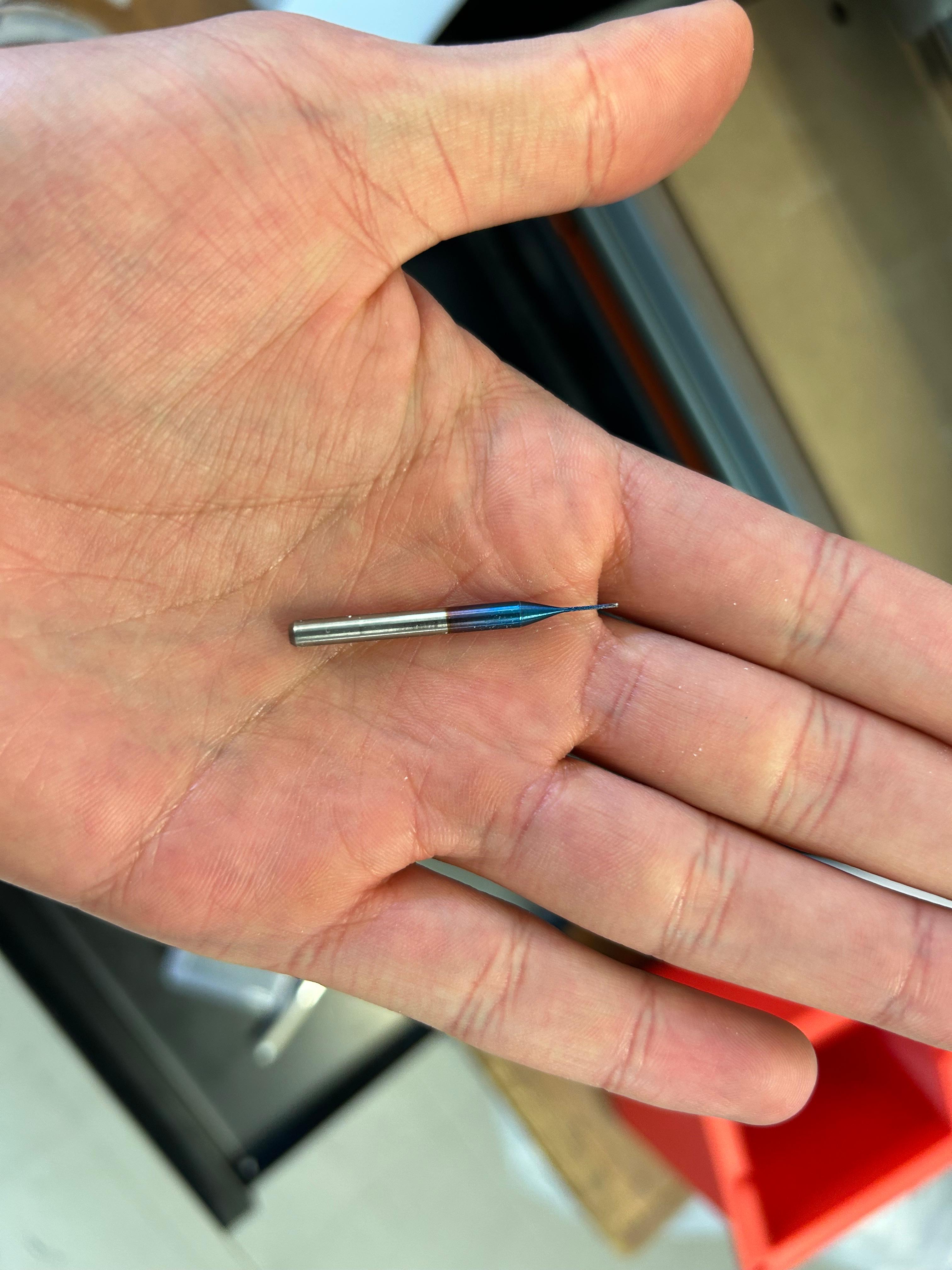
To put it on the machine, there is a tiny screw on the head of the machine, un screw it, introduce the drill on the head from bottom to top, and fix the screw when the drill is at a reasonable position.
Setting the origin
Now with the drill placed, we can set the origin of the machine. For this let's get familiar with the interface of the machine.
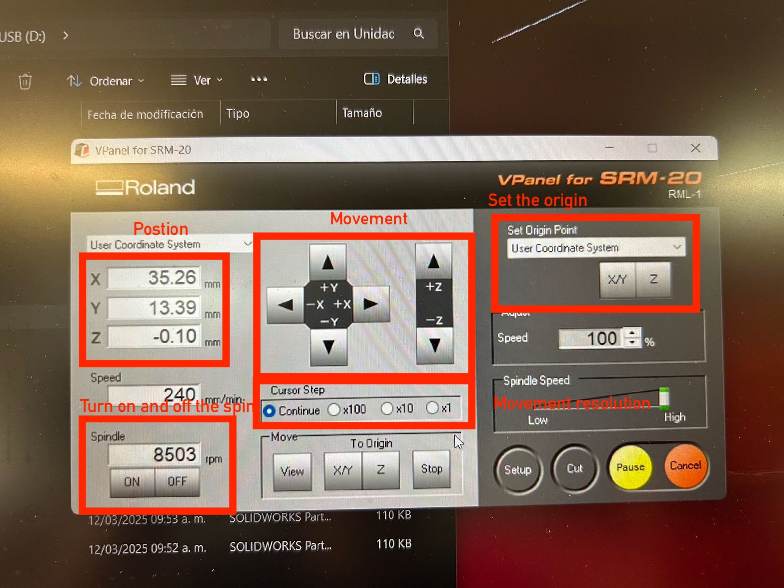
For this process we will use the movement buttons, cursor steps/movement resolution and set the origin. Remember, the file will start on the left down corner and will work to the right up corner. So, as this machine does not have fix plates on the sides we can go set the origin
on the very left and bottom of the copper plate. Using the move buttons on the interface, move the head to the position, you can lower the drill so you can have a better look of where the head is.
You can also use the movement resolution to move on slower steps:
-
Continue
This will move the axis as longs as the button is pushed, I don't recommend to use this option for the z axis because the drills can be very fragile and the axis moves quite fast. -
x100
Moves the axis millimeter by millimeter -
x10
Moves the axis in a lower resolution, so it is more precise. - And so on...
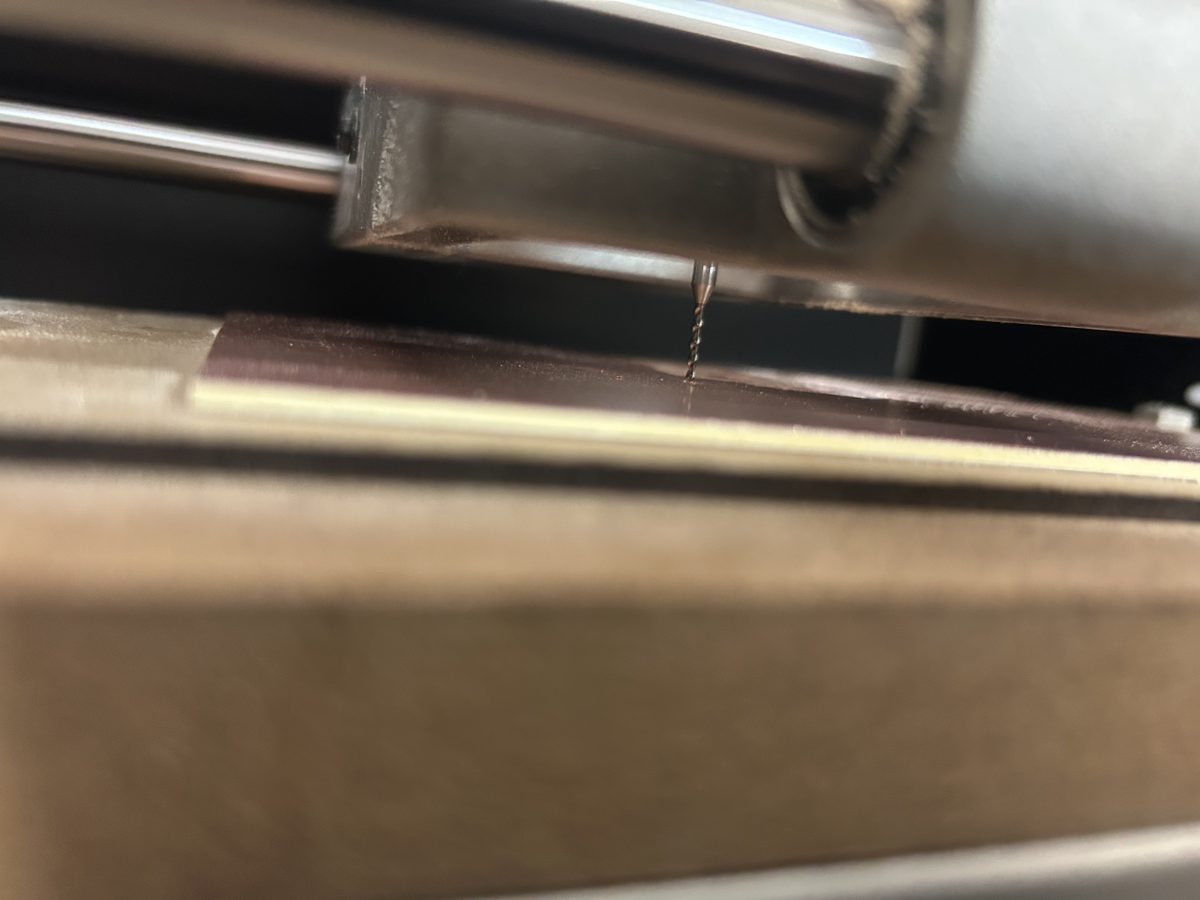
The head is on position to save the origin just click on the "x/y" button on the origin section, a popup alert will showup asking if you are sure, just click on yes and there you go. you had set you x/y origin. Now for the z before setting the z origin I recommend to run the edges to make sure everything is alright and the program does what yu want to do. Check further to know to run a file.
Now the z origin, is highly recommended to turn on the spin so you can hear when the drill touches the plate. So, turn on the drill and move on small steps the z axis as closer as you get to the plate, go to a smaller step down to 1 step.
keep moving the axis until you notice a change on the sound or material start coming off the plate, once the sound changed, you can go up 1 step, and click on the z button of the "set origin" section.
Alright we have both origins, we are ready to run the program. NOTE, in this machine and for safety reasons you have to close the front door to move the machine.
Run a file on the machine
This might sound funny but click on the round button "run" jajajaja and watch the following video
NOTE, I recommend to erase all the files on the software memory and leave just the one you want to run.
NOTE, the machine will automatically start doing the process once you run the file, so at this point everything should be ready to start. Besides that just keep and eye on the machine for anything that could happened and remember, first the holes, then the tracks and for lat the edges.
Once ended the process
Once ended the process of the first file, the machine will go to a home position, you can run the next file, but I recommend clean the plate, because it will make a lot fo dust. You can either clean it with a vacuum cleaner or a mini broom and then run the next file.
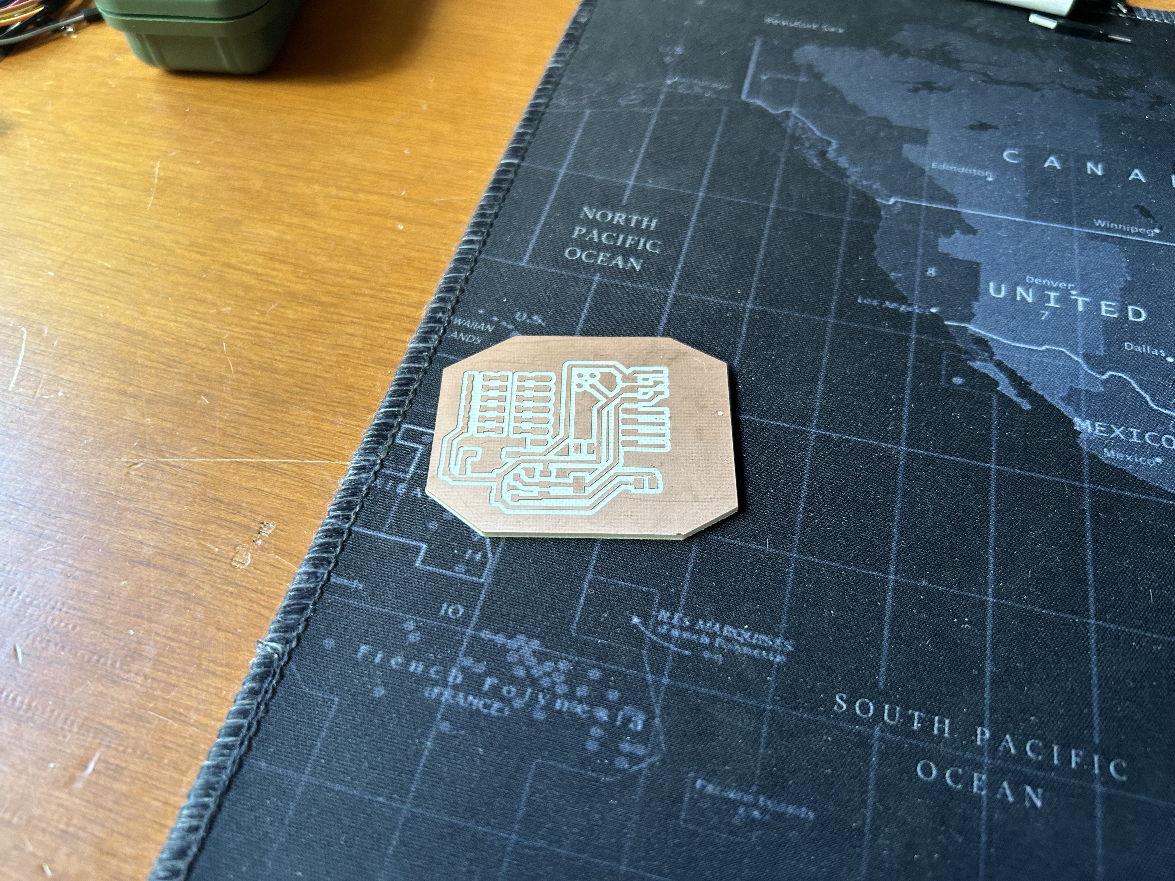
The plate is ready
Once the plate is ready you can take it out of the bed of the machine, and the next step is solder the components, make sure you have all of them before making the plate (read further).
I soldered them with solder iron and solder paste, first I had no idea of how to do it, bu I asked a classmate and he told me, first add some tin onn the plate track, then melt that tin again and add the component.
There you have a pin soldered, then just add some tin to the other side and make sure to make contact between the component and the track, and that's it.
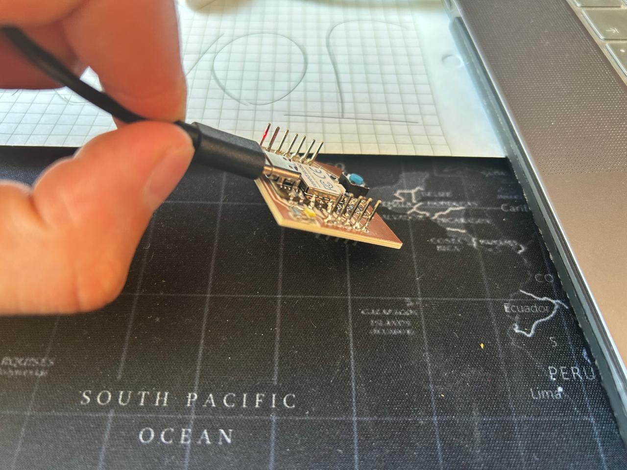
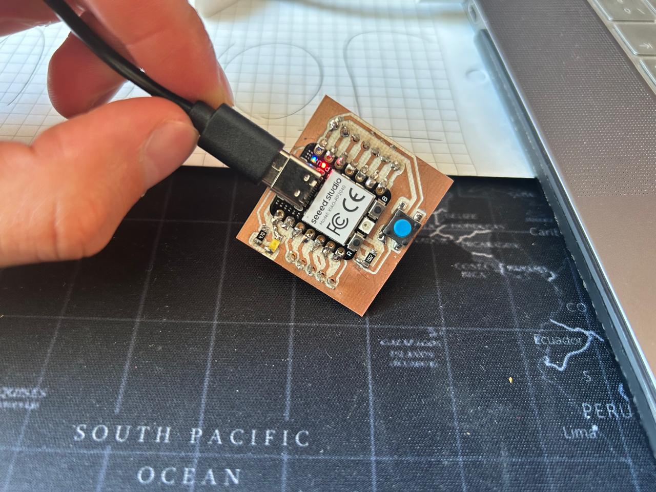
The final product
The final product is just a xiao rp2040 with a led, a push button and pins, so I can connect anything I want and make the everyday program of the button and the led.
The files
Special considerations and Print the SVG and check the components
Modification of the circuit design
I had to modify the entire circuit because I made it without checking which components do we had, and I even added a component that I wasn't even going to use, so everything wrong. I had to recycle the first plate.
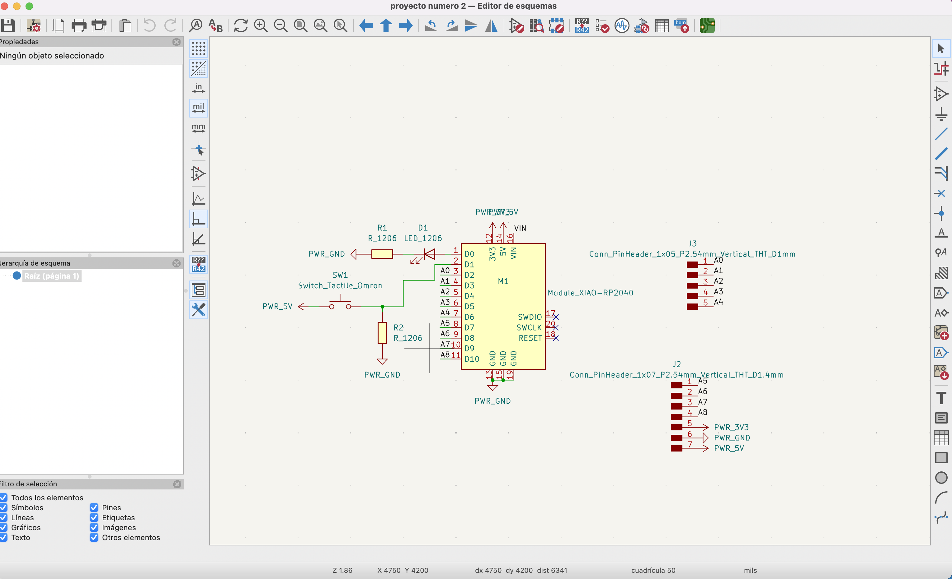
And a classmate told me that I have to check the footprints of the components so everything fits perfectly, so I redesigned the plate and this was the result:
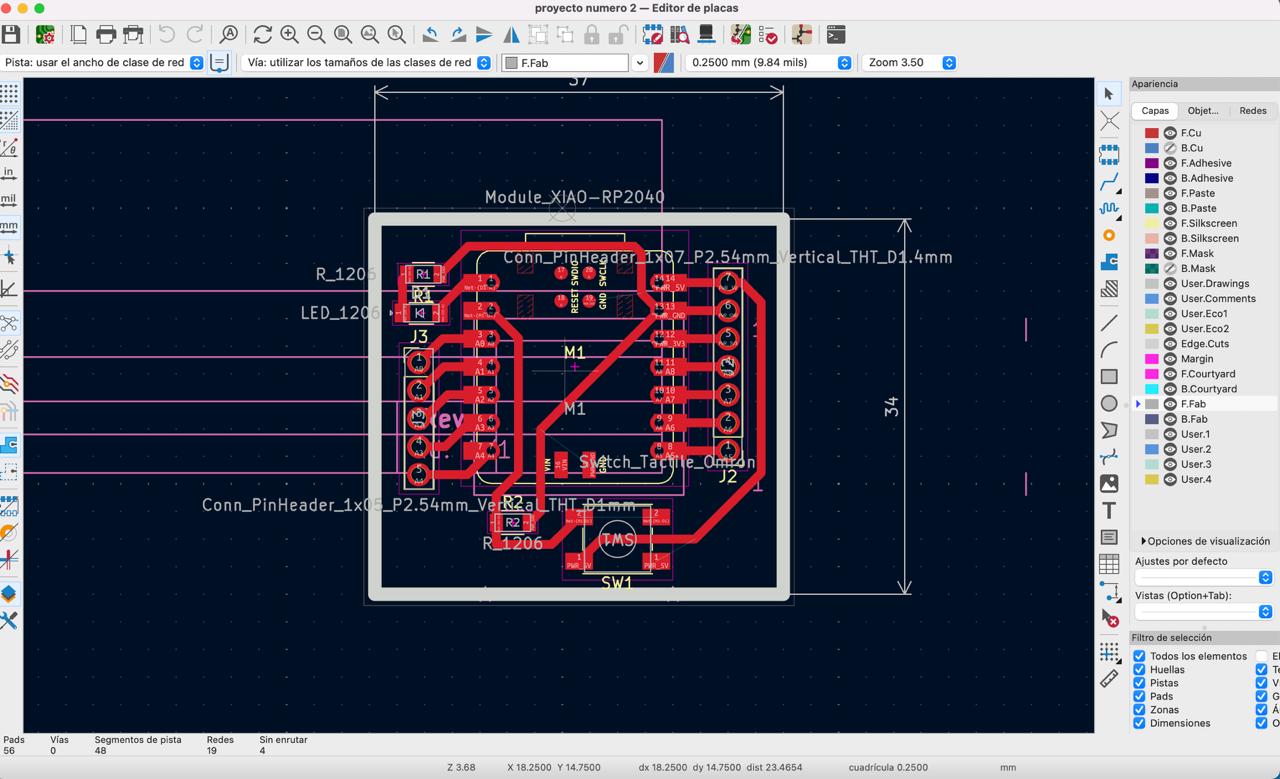
In this new plate I just added a led, a button and pins to connect the sensors of the following weeks, the micro processor is a xiao rp 2040 and the button has a PULL DOWN resistor.
Then I followed my classmate advice and printed the new circuit on a paper, to do this I just clock on the print icon on the upper menu (the icon between the button to set the dimentions of the SVG file and the export button). The circuit printed in a real scale, so I went to the fablab and looked for the components I needed and placed them where there were going to be, this gave me a green light to make the process once again and create the final circuit.
Footprint modification
While I was making my new plate I needed a 5 pin 1.54 mm holes and there was just a 1mm foot print, so I opened the footprint editor, looked for the component I wanted to edit and opened it. I had no idea of how to edit this footprints so I just read the option, double clicked on some others and found hout to edit the size of the circles. I didn't had the sizes of the holes I needed so I opened other footprint with the sizes I needed and copy them on the one I needed. It was easier that I thought.
The next question was: ¿how in this world do I upload the new dimentions on my pcb editor?, easy. I saved the footprint and went to the schematic editor, there I deleted the old component and added the new one with the new sizes. Then I just uploaded the pcb editor and voalia. The sizes I needed.
Z axis extra load error
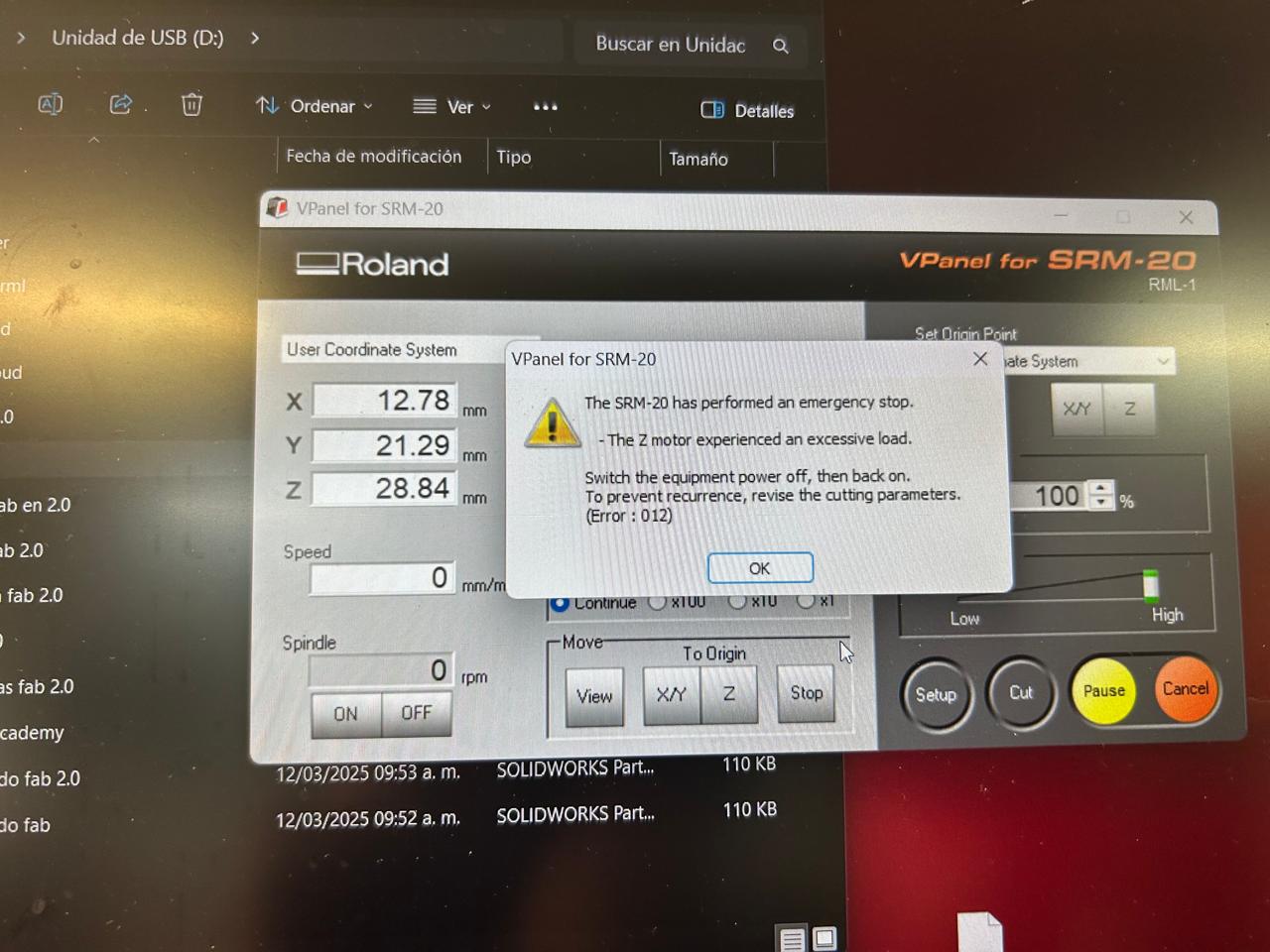
When I was doing my first plate this error came out, saying that there was to much effort on the z axis, so the teacher told me to lower the speed on the MODS CE file. And I recalibrated my z axis just a little upper. and voila, problem solved.
Unknown process error
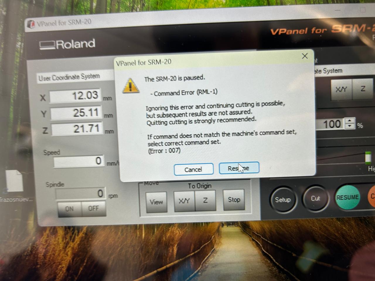
This one gave me a lot of trouble because I has no idea of what in this world could be making that error. The error gave me the option of keep going with a possible fail on the design but it just restarted the process and
stopped on the same fluffy part, I remade the file on MODS CE, I edited some tracks on the circuit and still the same error.
I spent like 3 hours trying and trying different things to solve the friendly error but nothing. Until god touched me and illuminated my head and a classmate told me "I like to set the offset at 2".
THE OFFSET, it has to be the offset, thank you classmate. I changed the offset from 4 to 2 on MODS CE and god thank you it finally worked, then I could start soldering the components and finally get to the final result
The final final result
Will it work?
I figured out 2 ways of knowing if my plate will work or not. The first one is with the multimeter, it has a function that creates a sound when there is a electric connection between two pins or objects you touch with the wires.
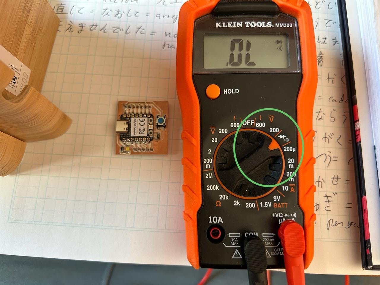
With this configuration we just have trough every connection/pin on the circuit and if it sounds or give anything but 0, then we are alright. Just watch this video:
The second way I know is connecting something and see if it is working. In my case I connected a led and turn it on with the push button. But to make it we have to first install the programming language on the micro controller. See next part
How do I install the programming language?
This micro controller has 3 possible languages to program it, the first two we are interested in are arduino, and micropython. I decided to do micropython, because it's easier to type it. So, how do I install it, just look for it on internet
"How to install micropython on a xiao rp2040", and This link will appear on the first option, it is the official page
of seeed studio, and it explains everything, step by step how to do it, but here is a quick review.
Fist, you have to install the latest version of Thonny
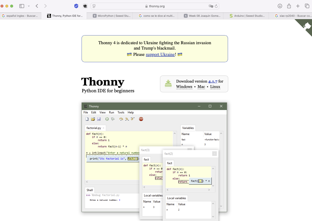
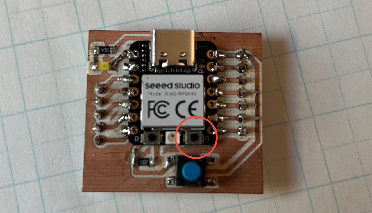
Then open it, go to tools/options on the new window, go to the "Interpreter" option and there select "MicropPython (Raspberry Pi Pico)" and leave the, "detect automatically" option. Leave the process there and take your xiao rp 2040 and press the "B" button while connecting the micro controller to the pc.
If everything went right, on your pc should appear a "RPI-RP2" disk, like if you connected a USB, that is the menu to upload the language.
Go back to Thonny to the window you left it and click on the lowest option that says "Install or update Micropython". A new window will appear with four lines, the first ine has to say the name of the disk that appear on the computer, the second one you can't edit it.
The third one has to say "Raspberry Pi * Pico / Pico H" and the last one the option with the higher number. Click install, wait until it is done and clothe thw windows. IF everything went right, there should appear a message that contains the words "Raspberry Pi /Pico H",
"Rp2040" and "Help()".
Programming it
Now we can start programming with Thonny. The same page of this tutorial has some example code to use the rgb led on the microcontroller, so we ae going to use those codes to see everything is connected. Let's see the code
from machine import Pin, Timer

led = Pin(25, Pin.OUT)
Counter = 0
Fun_Num = 0

def fun(tim):
    global Counter
    Counter = Counter + 1
    print(Counter)
    led.value(Counter%2)

    tim = Timer(-1)
    tim.init(period=1000, mode=Timer.PERIODIC, callback=fun)
Now we can modify it to work with the push button, and the use this same code, with every other pin.
The final files
SVG track files final
SVG edge files final
rml holes file final
rml track file final
rml edge file final
NOTE, I should have specified this on the design week already, but here is it again, I'm using a seeed xiao rp 2024, which uses a raspberry 2040 micro controller
Learning outcome
Be curios and click on everything if you don't know how to do it, or ask but do it.
Read the errors
And don't leave everything to the last, I don't believe my self anymore in this one, I said it on the beginning of the course and still doing it so...
I'm done :( I want to cry of happiness
The last issue
I found out that the led I put on the final product wasn't working properly. First I thought it was broke, then I checked my diagram to see everything is correct, I double checked the code to make sure y typed the right pin,
the output and everything, I quit a few days and tried to solder a new led, but before putting a new one I thought, what if I connect a normal led to the same pin and voilà, this happened
Everything was working right, and then I thought, how do I connected the led? baaaaaaaaaaaah that ssssthing has polarity, and then I searched "smd led polarity" and this image came out:
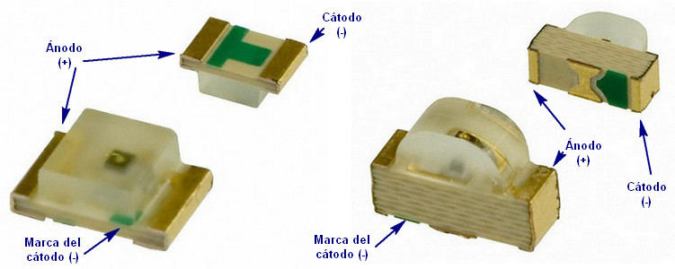
Now we know that the green thing on the upper side of the led is the negative. I soldered it the right way and god made light.
So, always check the polarity of the components