8. ELECTRONICS PRODUCTION
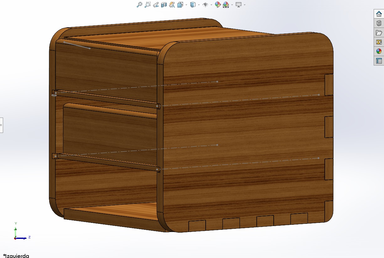
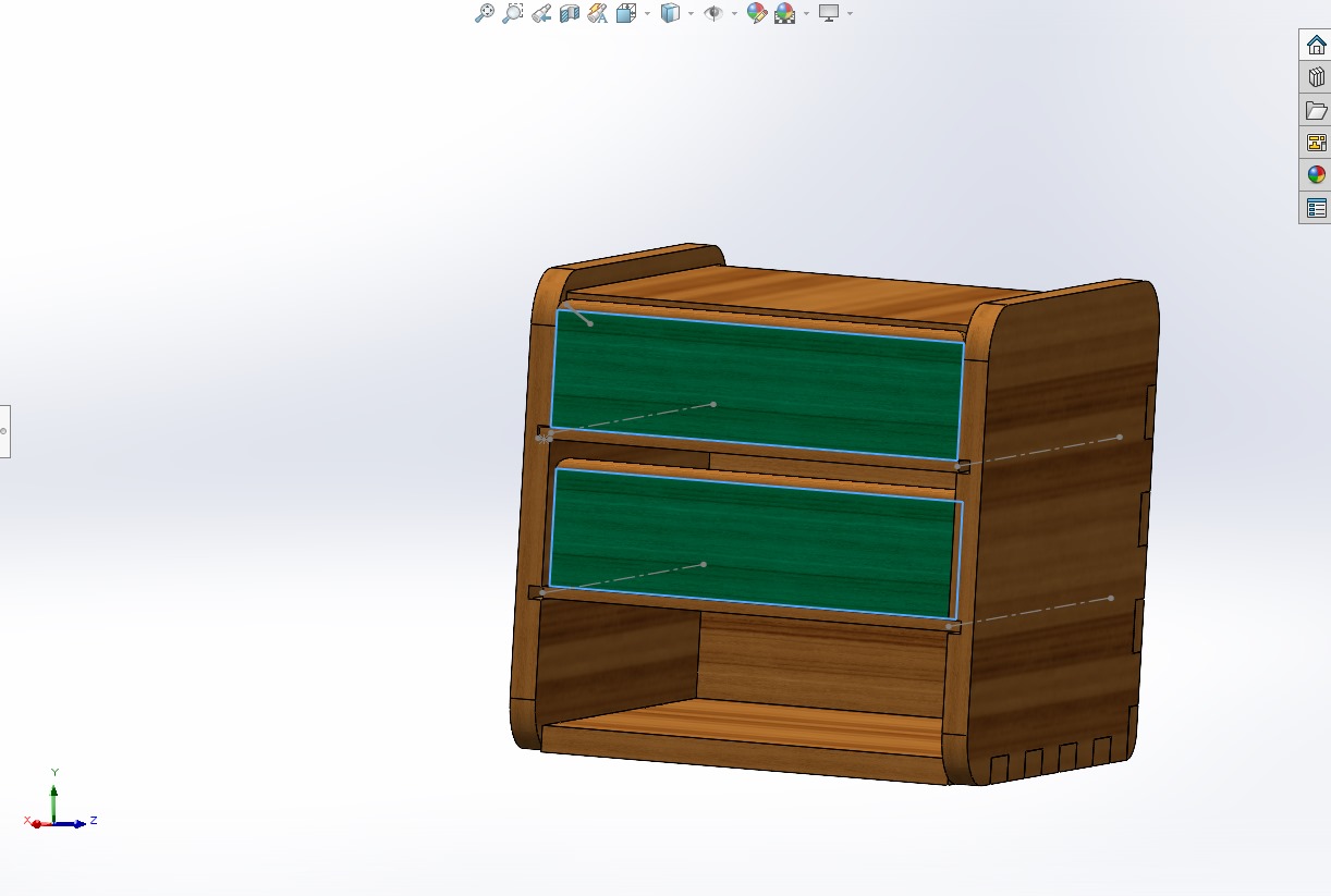
- This week the evaluators asked us to create something large (scale: 1m²), with any CAD program. In my case it will be Design + Mill + Assemble = Furniture. I will try not to use fasteners or glue, I will use finger joints to connect the sides and I will include curved surfaces.
- DESIGNING A FURNITURE IN SOLIDWORKS -
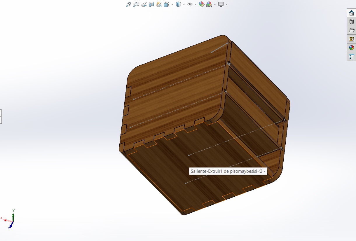
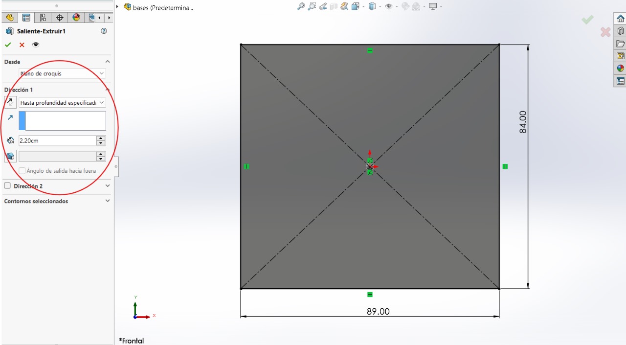
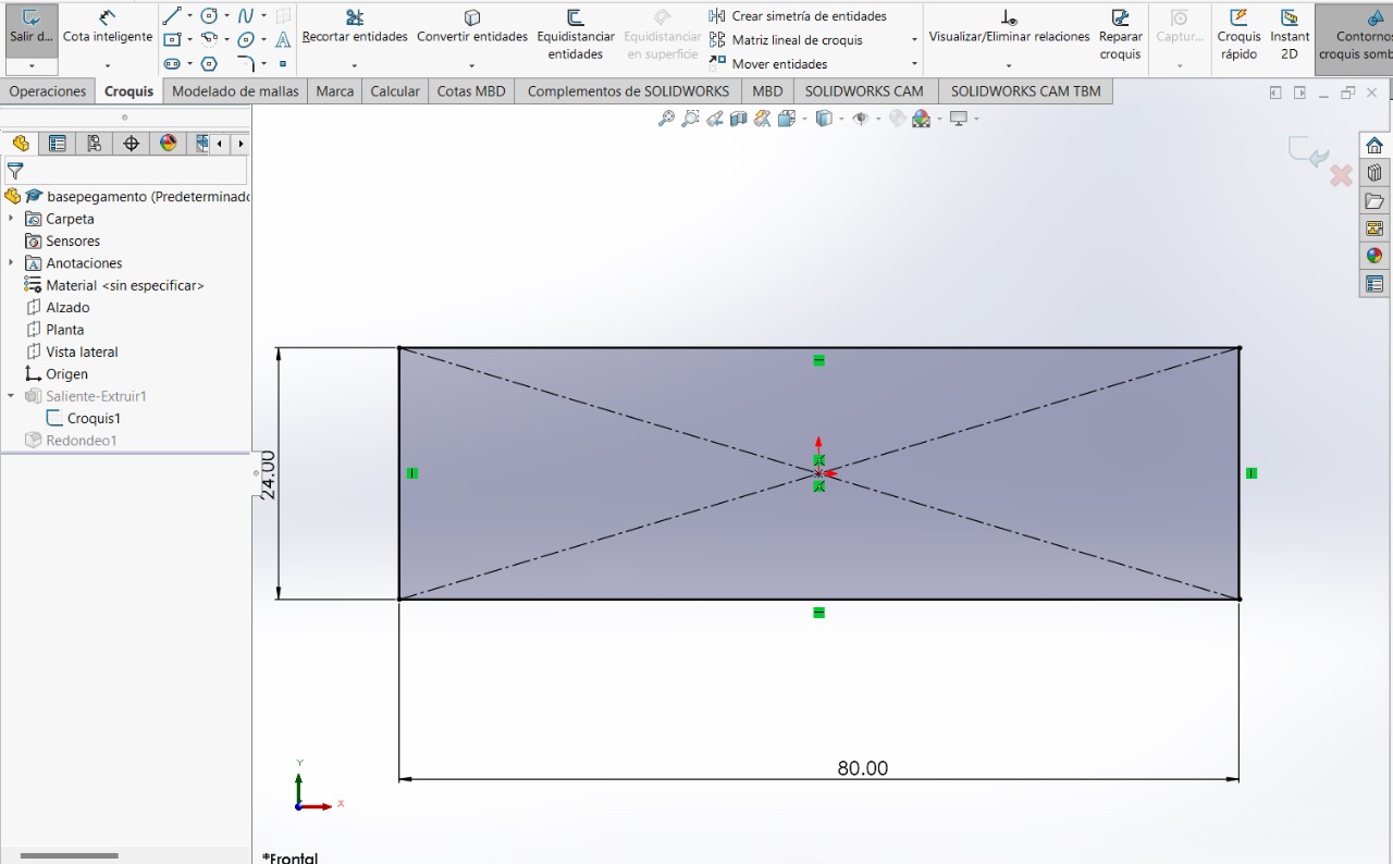
BACK PART
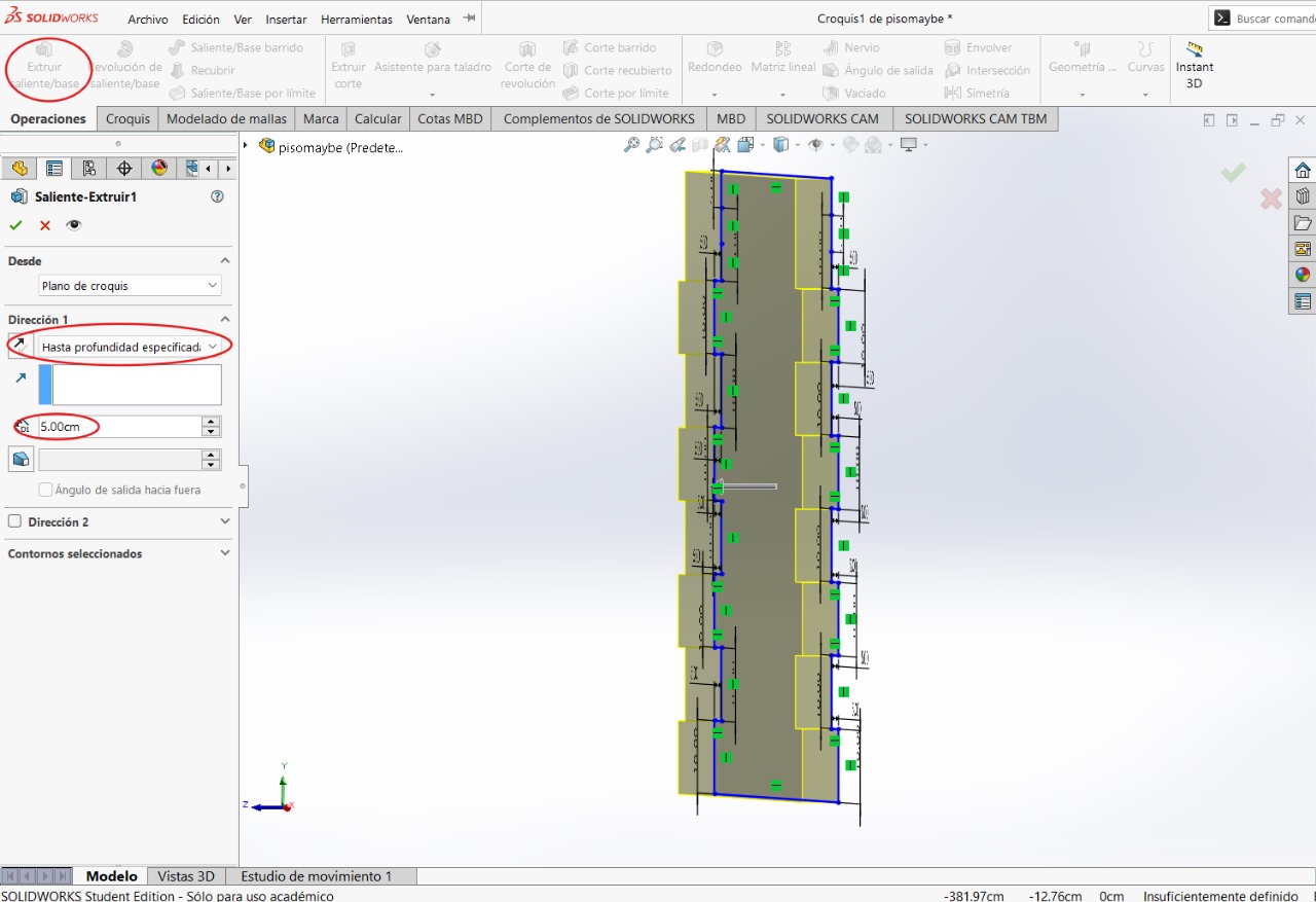
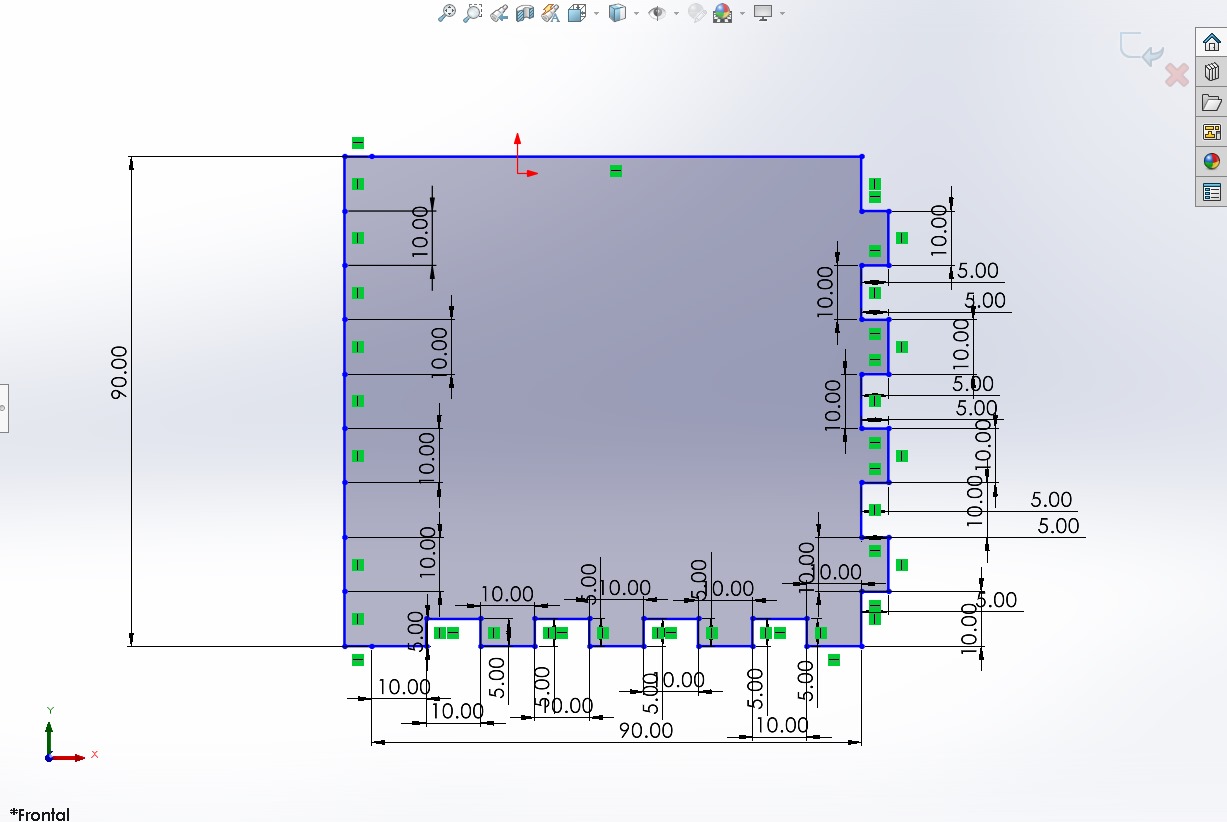
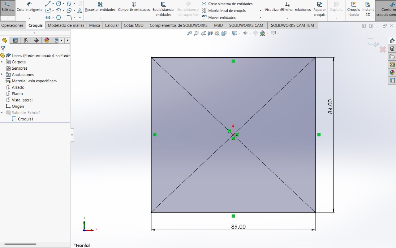
To be able to make the furniture, we'll start with the back part of the figure to establish values for the total size of the figure. It's worth considering that it would have been better to create the figures parametrically to avoid certain errors within the figure and improve time efficiency when creating the figure. However, I was able to make them this way with almost no problems. In the next figure, you'll notice that the furniture is in the same file. At the end, I'll explain how to join each of the figures. For now, you'll have to create each of the parts in different files.
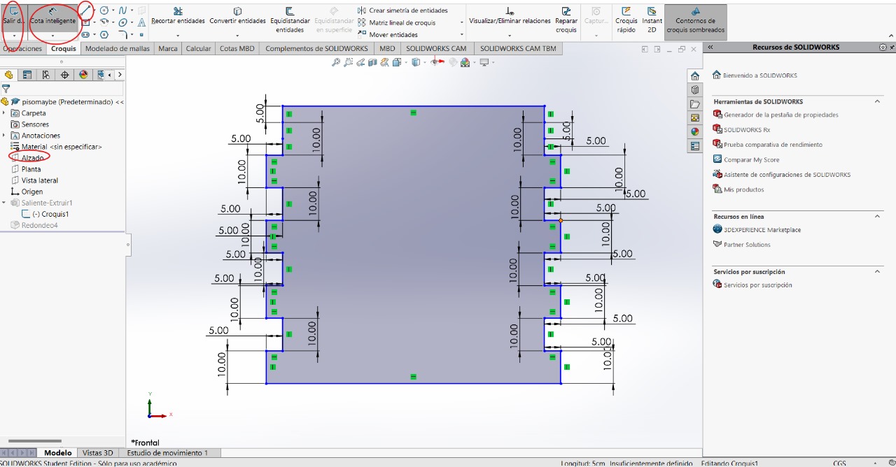
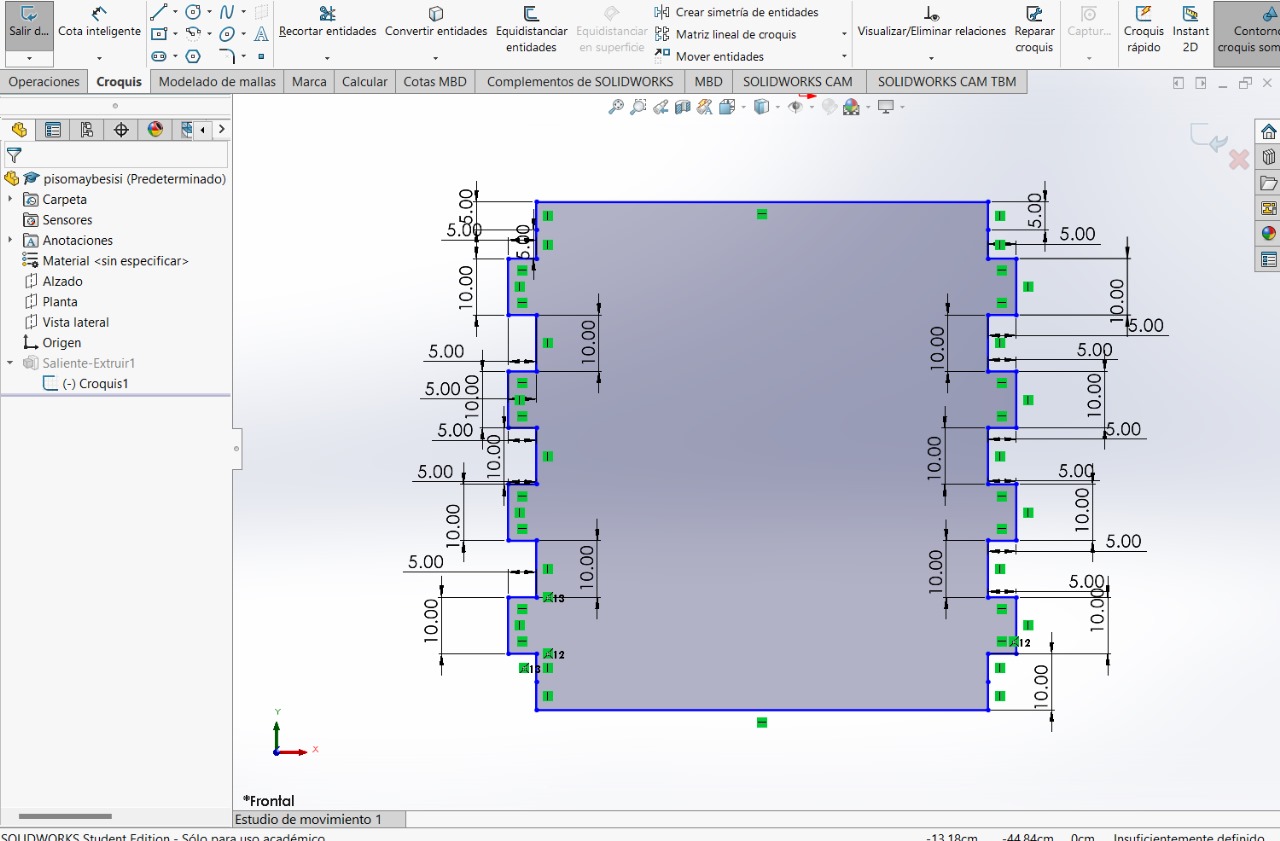
The next step will be repeated on all occasions: creating a sketch in "Front view", making lines and creating dimensions to give values to the sides
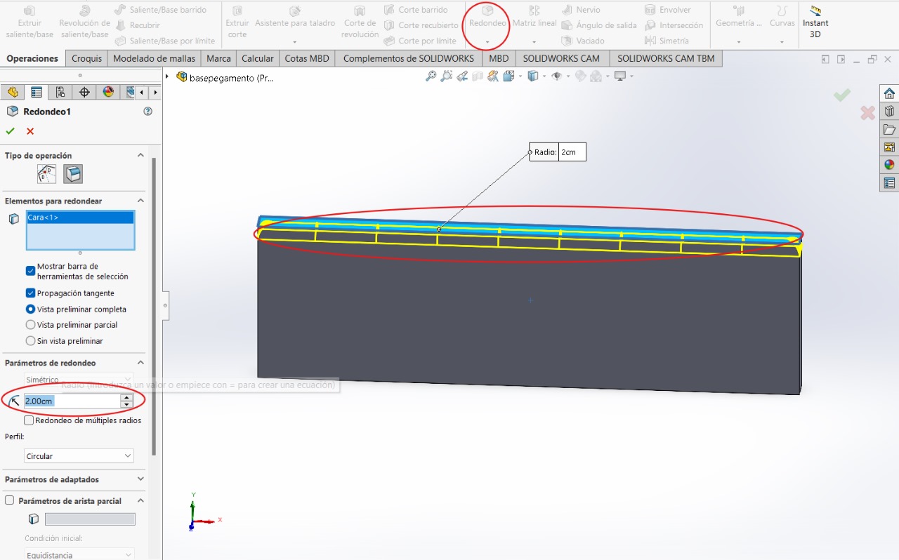
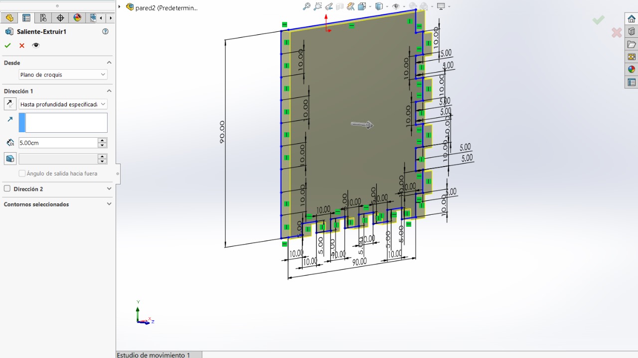
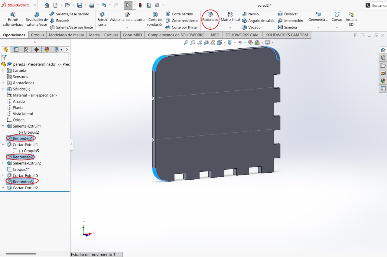
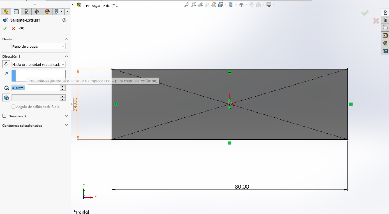
This step might ruin things when joining all the parts together, but if something doesn't fit, we can just go back. We can add some design to the figure with the "fillet" tool
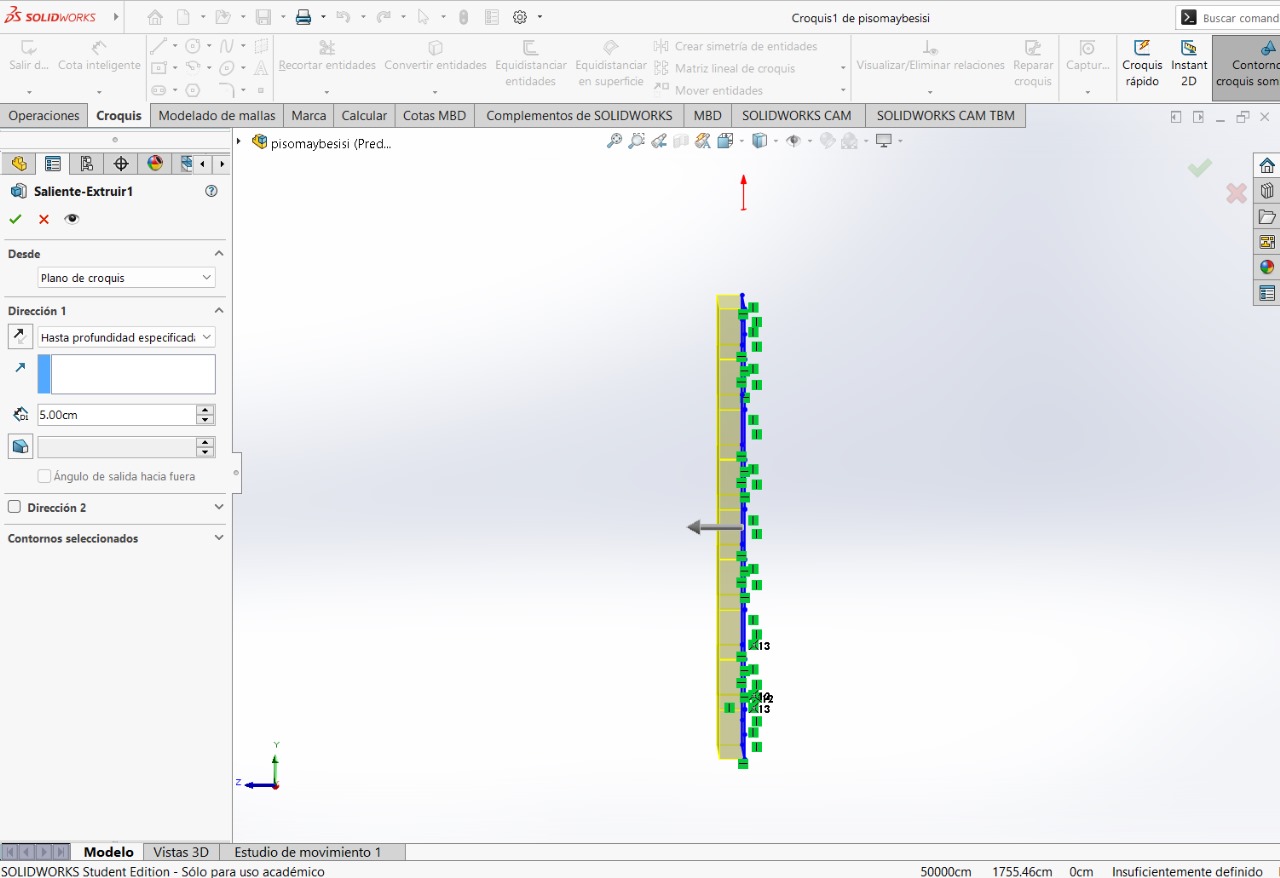
Without leaving the sketch, we can make the figure wider by entering the following values. This would be the final step for this figure. We save it with a name referencing where it will be placed or which part of the furniture it is, and then create a new file
BOTTOM PART
Repeated steps
Repeated steps
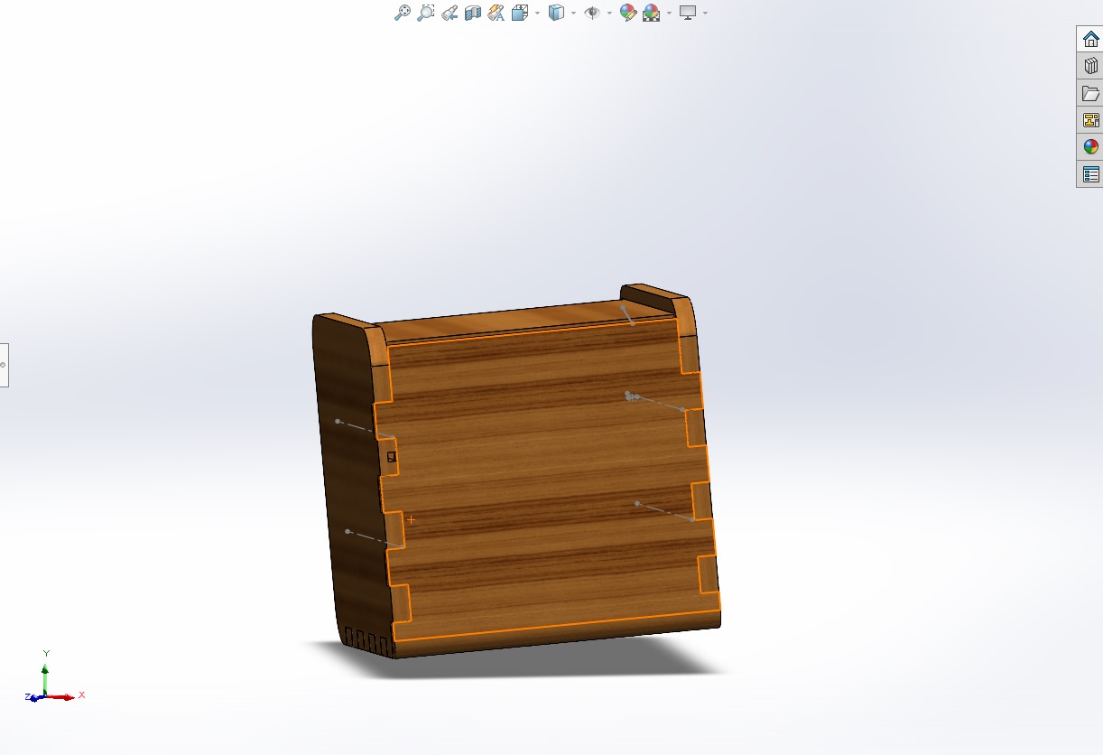
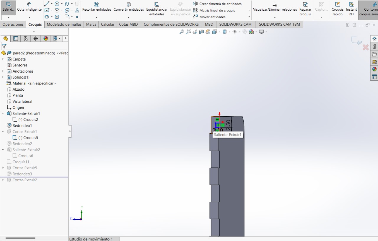
LEFT SIDE AND RIGHT SIDE
For the two parts, they will be the same, just create the cuts on the internal side of the figure.
Repeated steps
Repeated steps
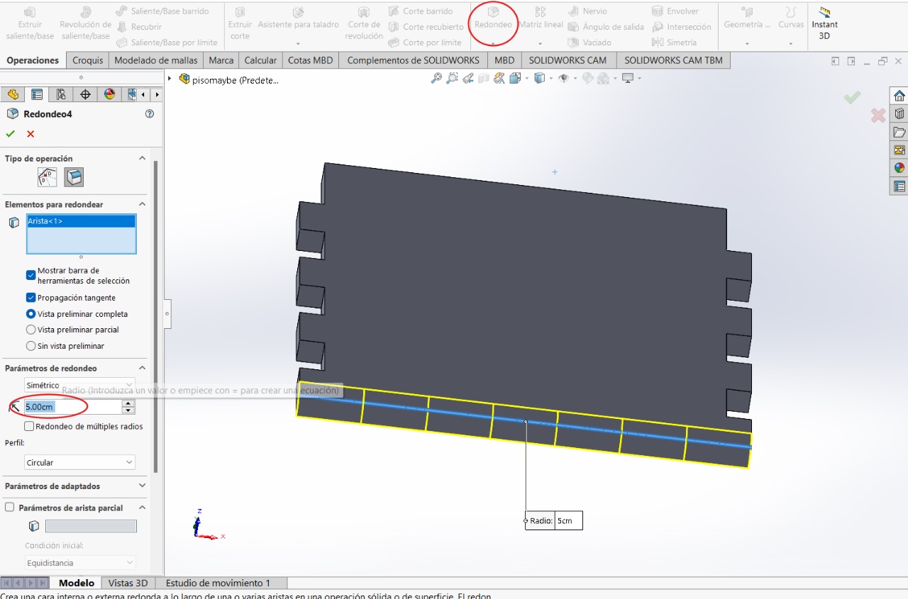
We will use "fillet" tool
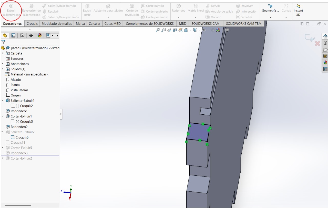
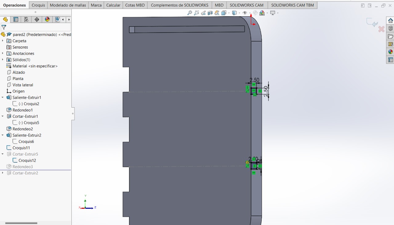
We will create a sketch on the side of the 'finger prints' to be able to create this square
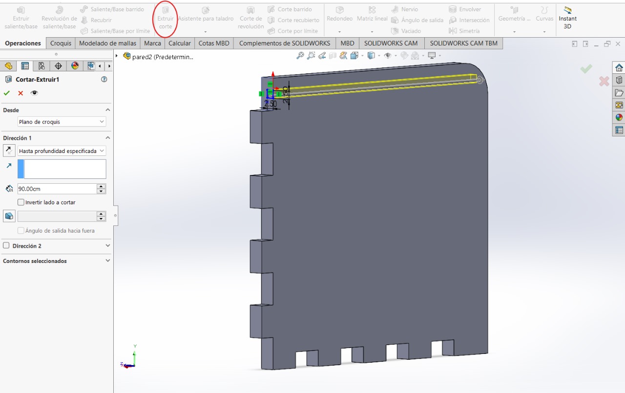
Without leaving the sketch, we will use the 'Extrude/Cut' tool
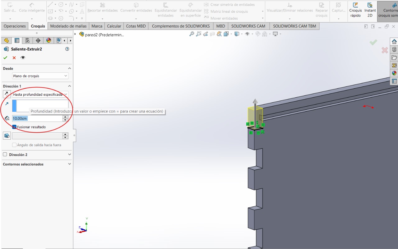
To fix this error in the first sketch, we will create a sketch in the indicated upper part and use the 'Extrude Boss/Base' tool.
For the next step we will need to create two construction lines, these will serve as guides to be able to complete the next step
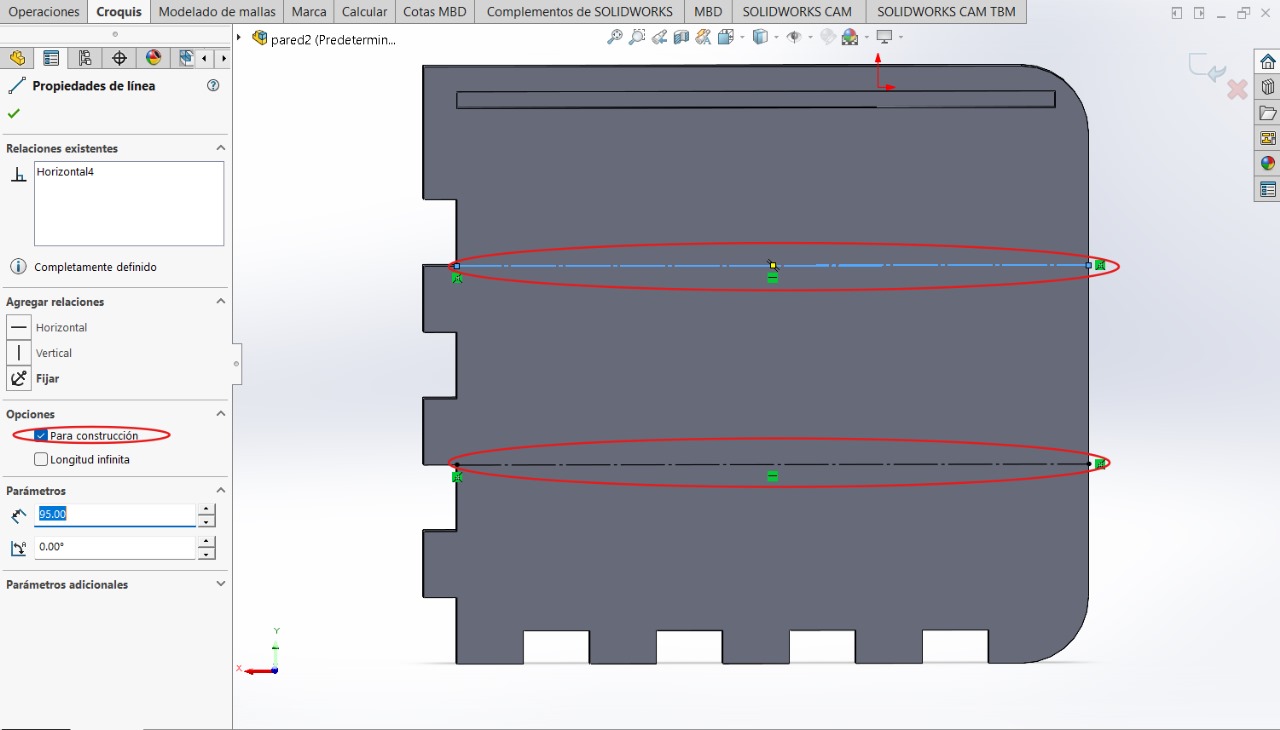
We will create these two squares and, just like with the previous steps, we will use the 'Extrude Cut' tool on both sketches
TOP BASE
This figure will be the top part of the furniture
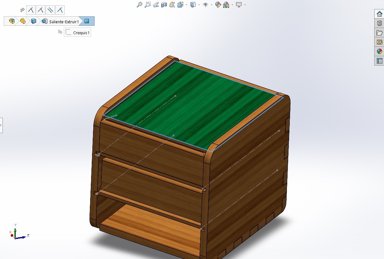
Sketch and Extrude Boss/Base
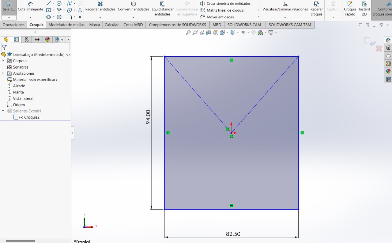
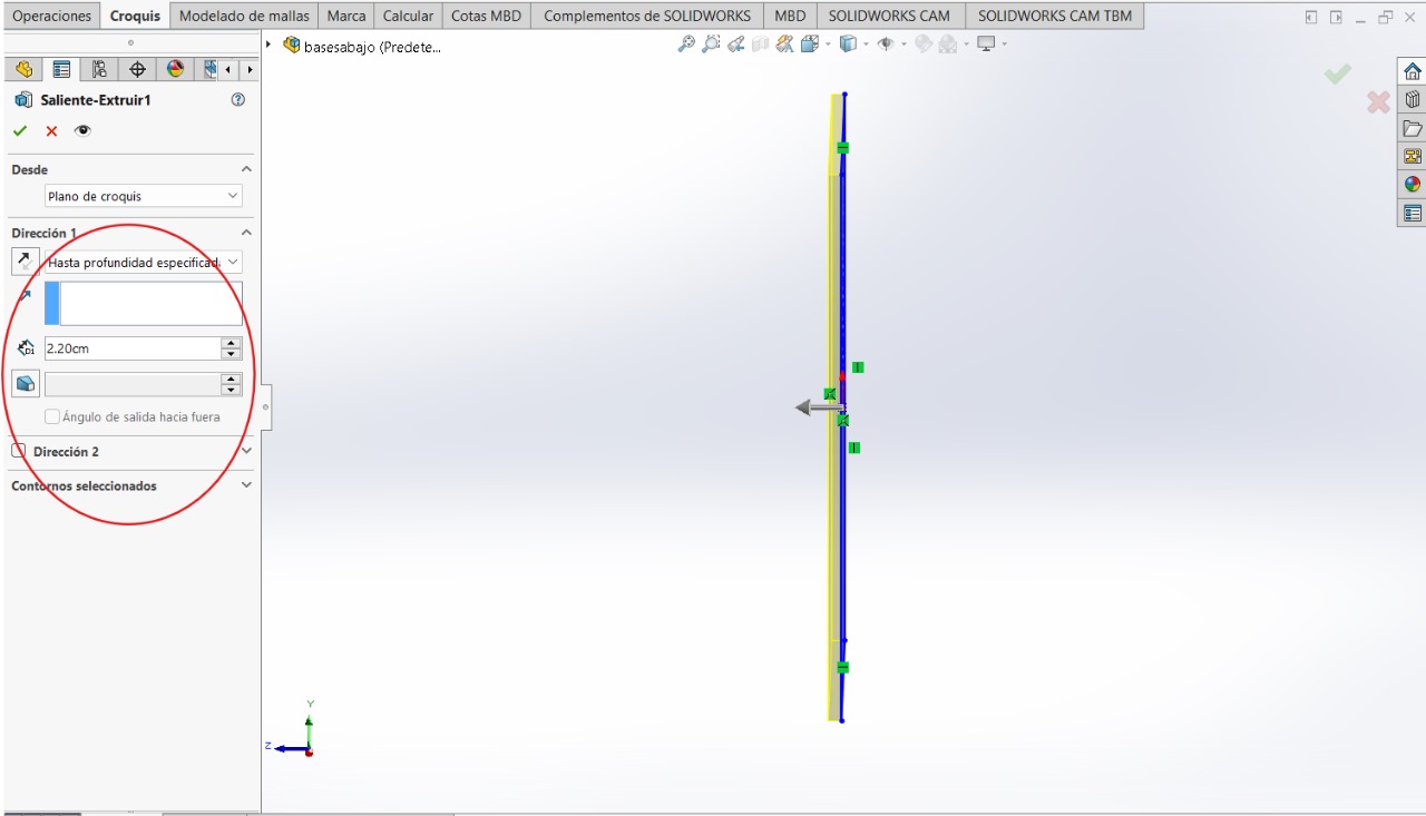
MIDDLE BASES
These parts will be the other two bases of the furniture
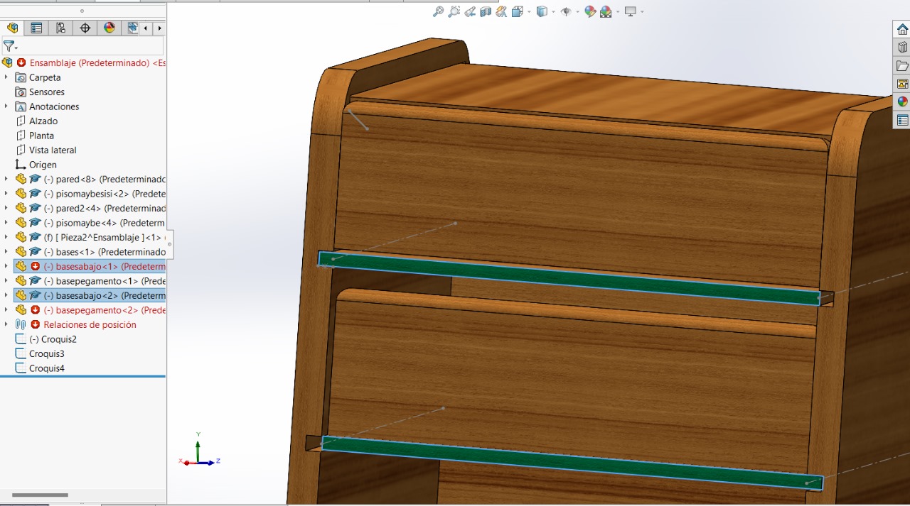
Sketch and Extrude Boss/Base
COVERS
These covers will be for moving the bases
Sketch and Extrude Boss/Base
Sketch and Extrude Boss/Base