7. COMPUTER CONTROLLED MACHINING
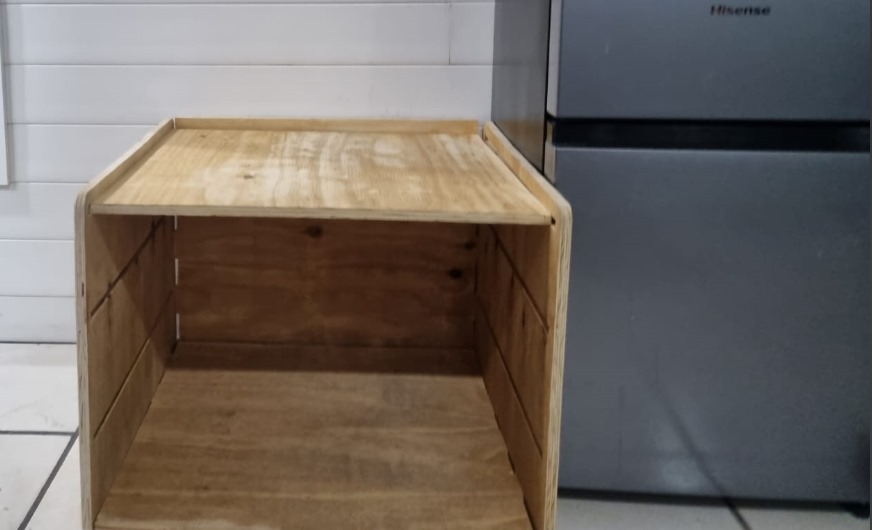
- This week the evaluators asked us to create something large (scale: 1m²), with any CAD program. In my case it will be Design + Mill + Assemble = Furniture. I will try not to use fasteners or glue, I will use finger joints to connect the sides and I will include curved surfaces.
- DESIGNING A FURNITURE IN SOLIDWORKS -
BACK PART
To be able to make the furniture, we'll start with the back part of the figure to establish values for the total size of the figure. It's worth considering that it would have been better to create the figures parametrically to avoid certain errors within the figure and improve time efficiency when creating the figure. However, I was able to make them this way with almost no problems. In the next figure, you'll notice that the furniture is in the same file. At the end, I'll explain how to join each of the figures. For now, you'll have to create each of the parts in different files.
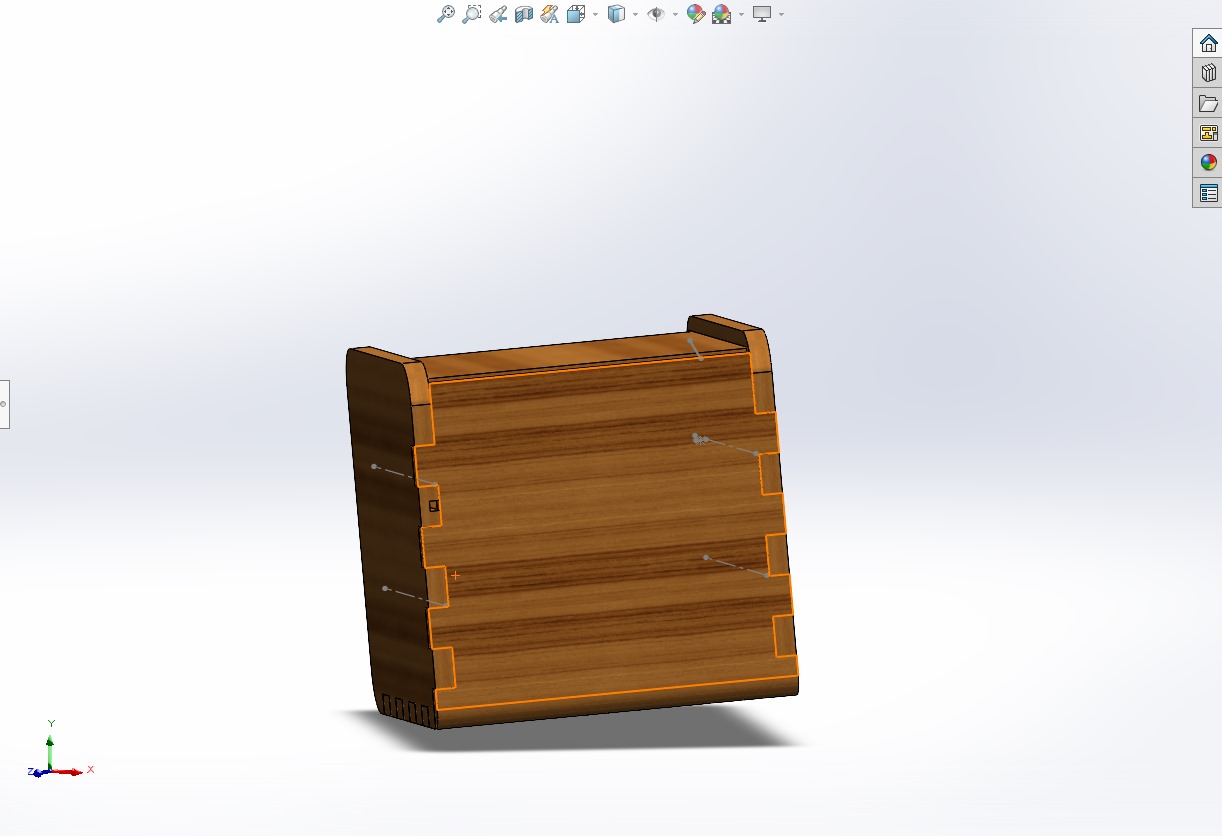
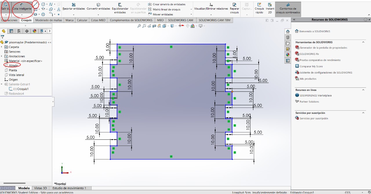
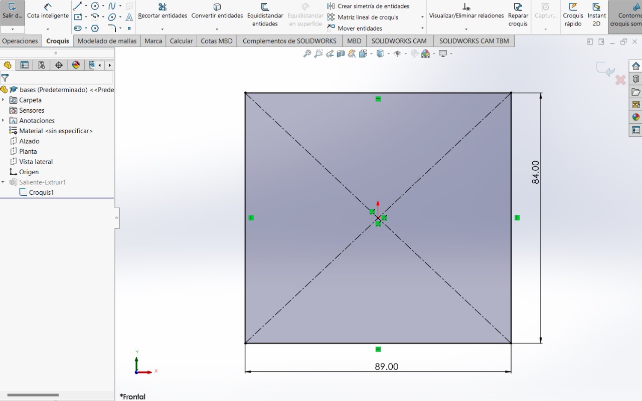
The next step will be repeated on all occasions: creating a sketch in "Front view", making lines and creating dimensions to give values to the sides
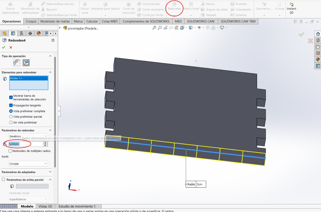
This step might ruin things when joining all the parts together, but if something doesn't fit, we can just go back. We can add some design to the figure with the "fillet" tool
Without leaving the sketch, we can make the figure wider by entering the following values. This would be the final step for this figure. We save it with a name referencing where it will be placed or which part of the furniture it is, and then create a new file
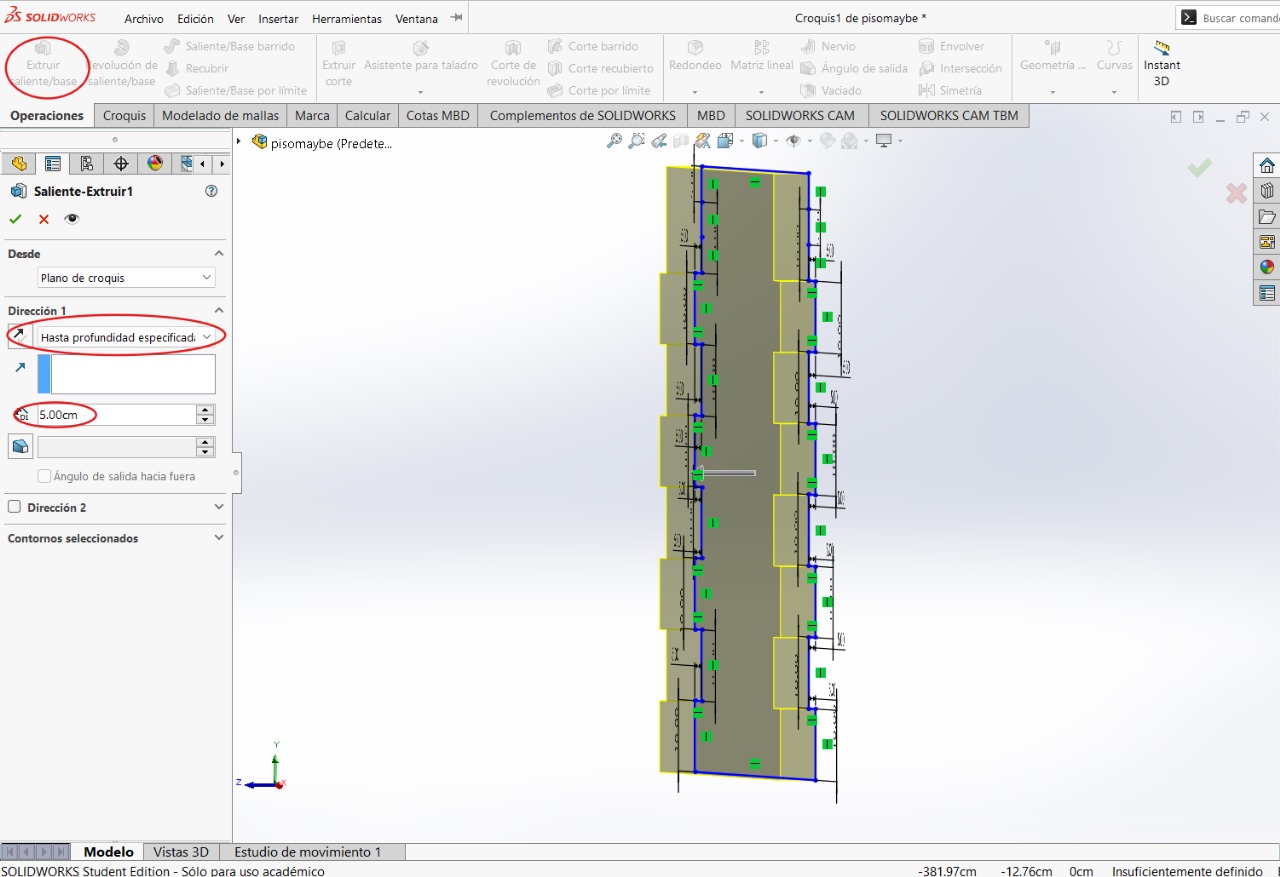
BOTTOM PART
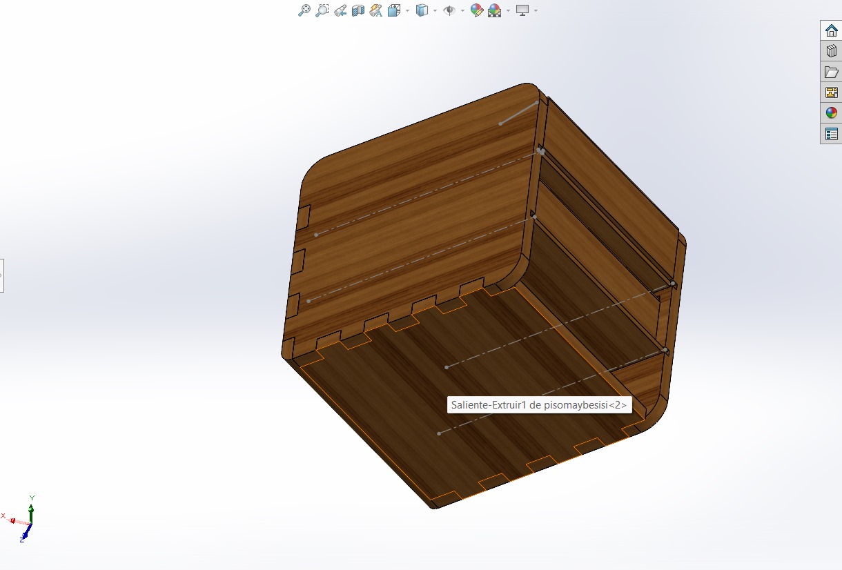
Repeated steps
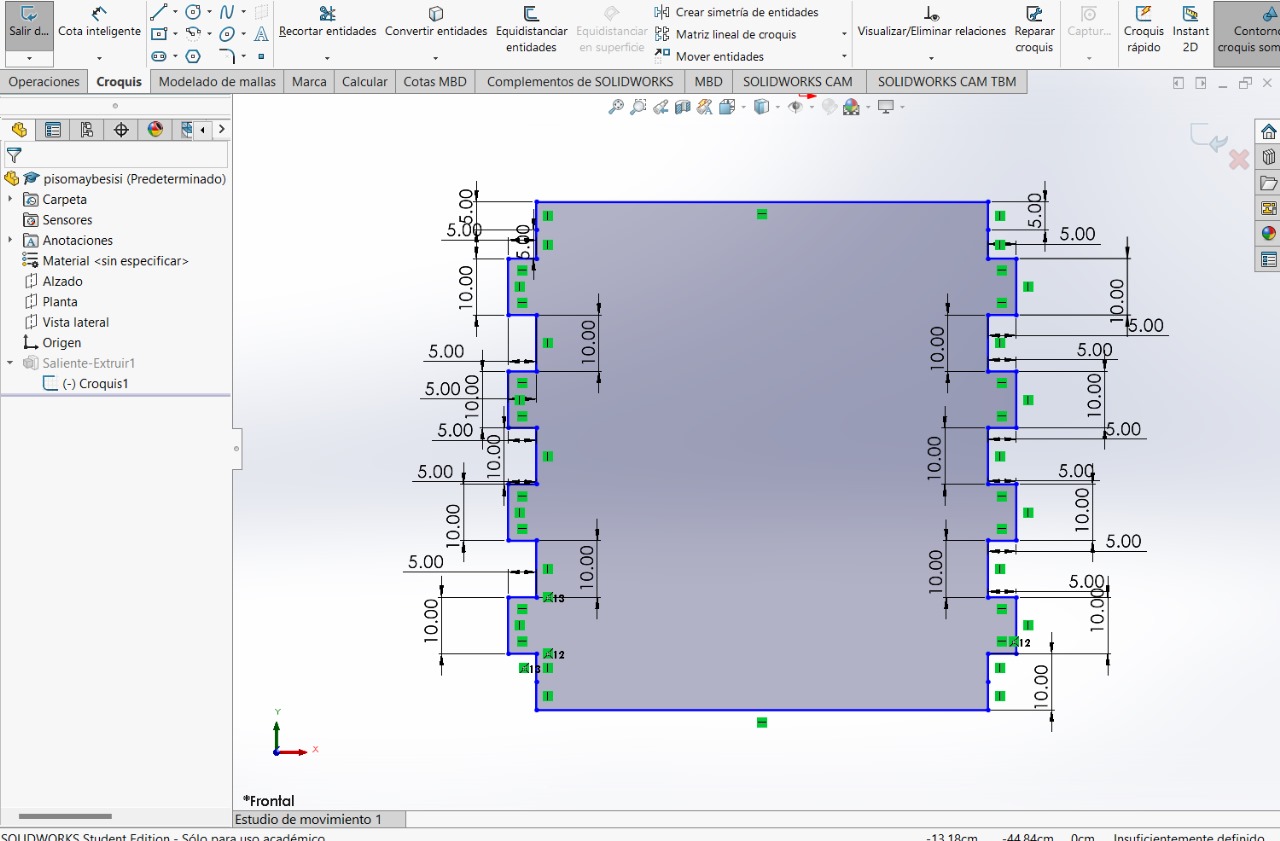
Repeated steps
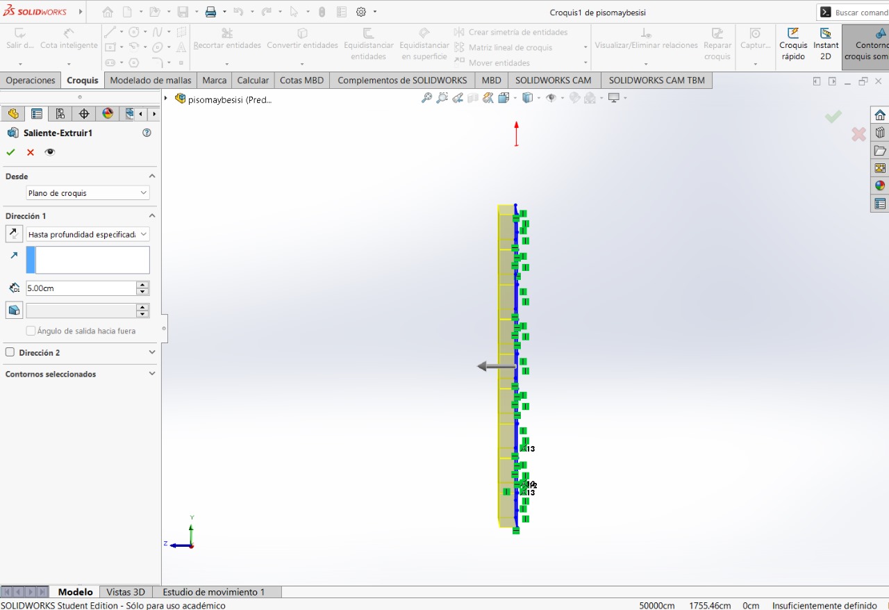
LEFT SIDE AND RIGHT SIDE
For the two parts, they will be the same, just create the cuts on the internal side of the figure.
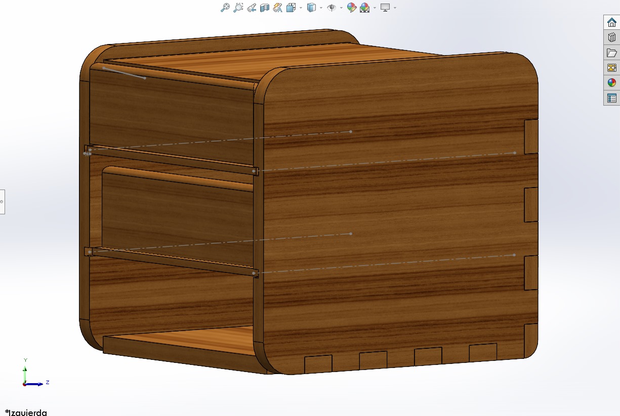
Repeated steps
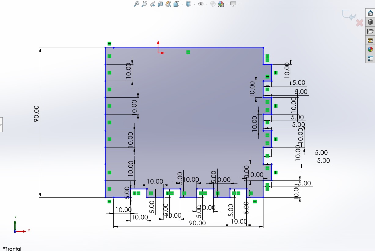
Repeated steps
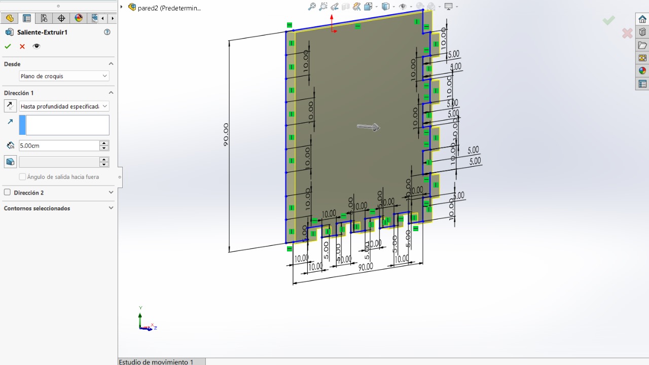
We will use "fillet" tool
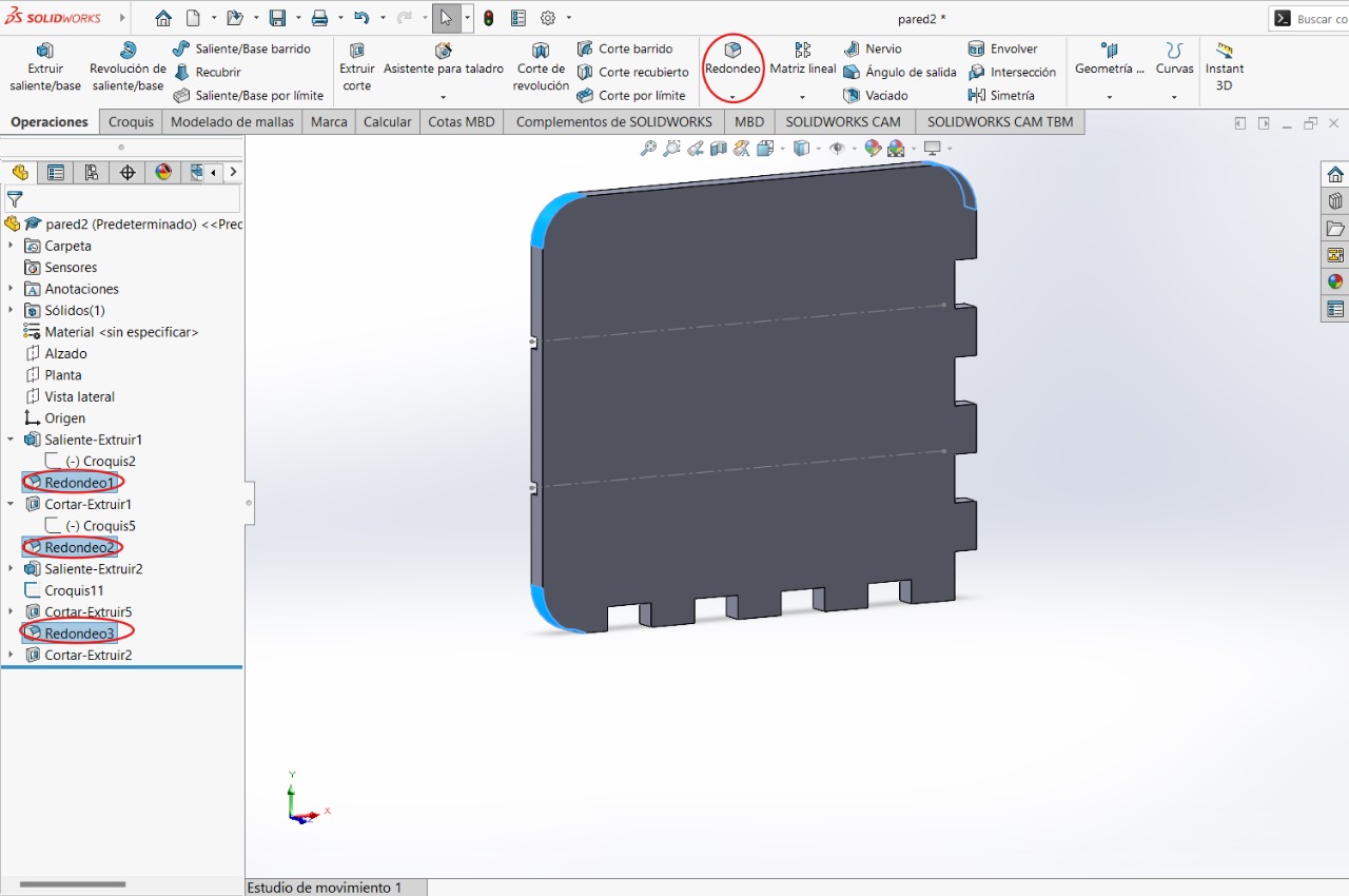
We will create a sketch on the side of the 'finger prints' to be able to create this square
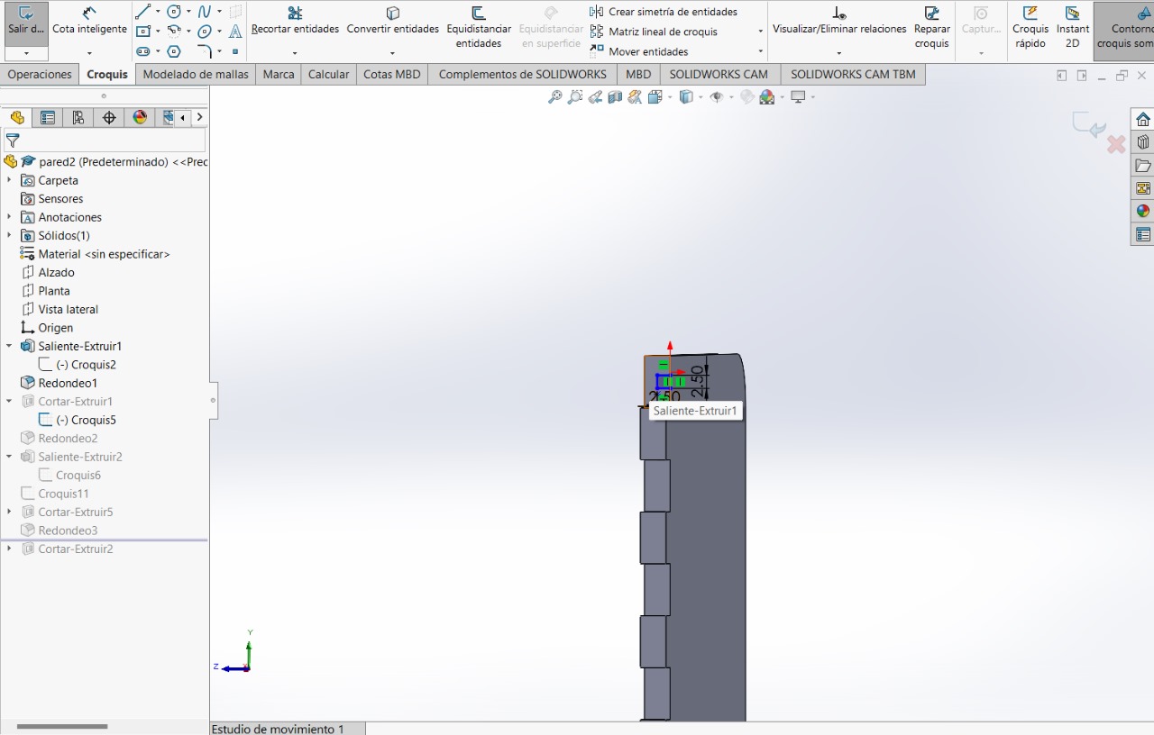
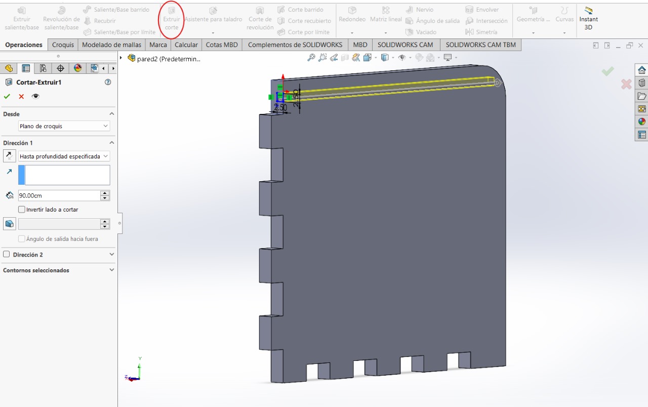
Without leaving the sketch, we will use the 'Extrude/Cut' tool
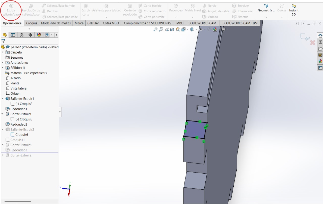
To fix this error in the first sketch, we will create a sketch in the indicated upper part and use the 'Extrude Boss/Base' tool.
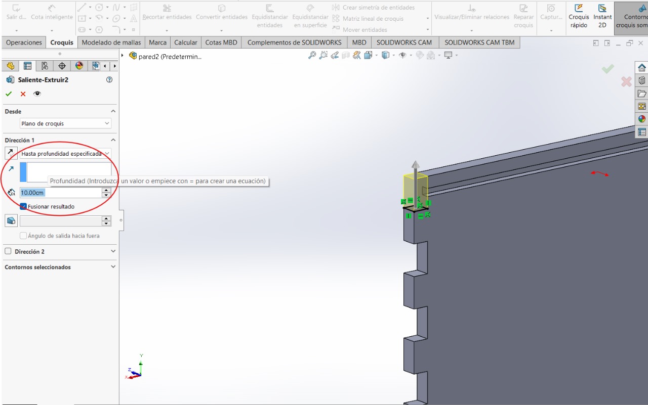
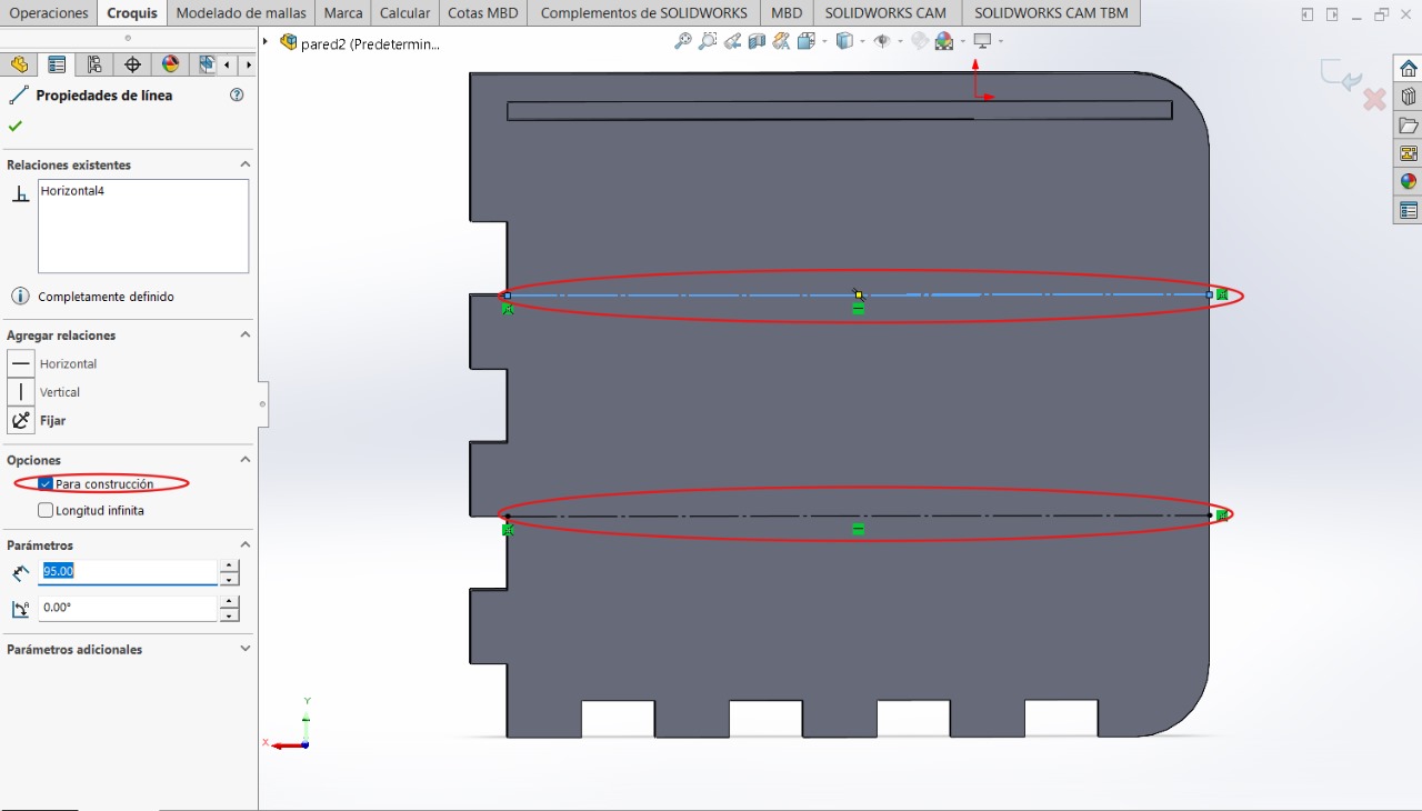
For the next step we will need to create two construction lines, these will serve as guides to be able to complete the next step
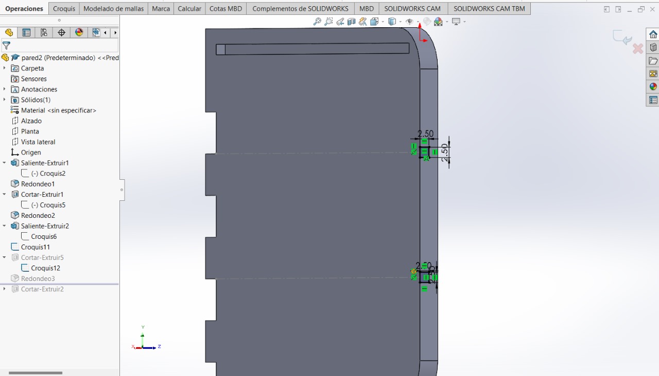
We will create these two squares and, just like with the previous steps, we will use the 'Extrude Cut' tool on both sketches
TOP BASE
This figure will be the top part of the furniture
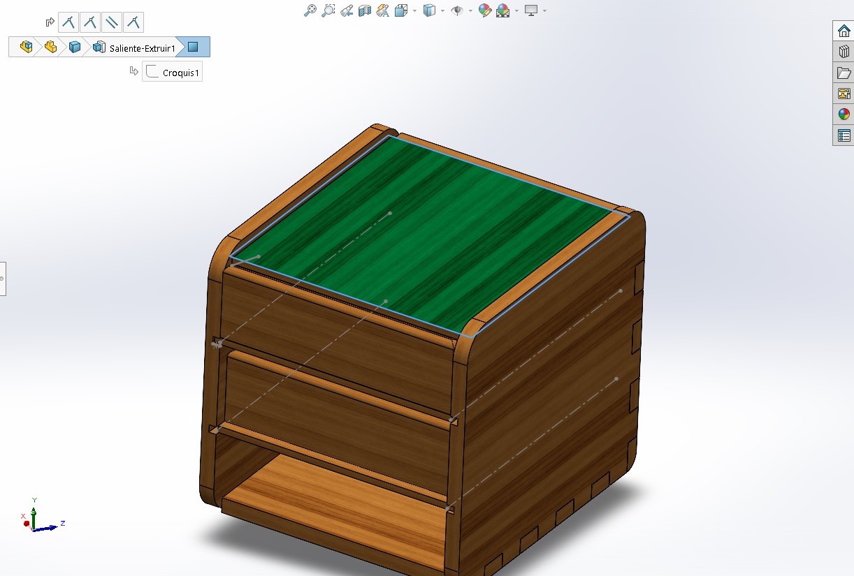
Sketch and Extrude Boss/Base
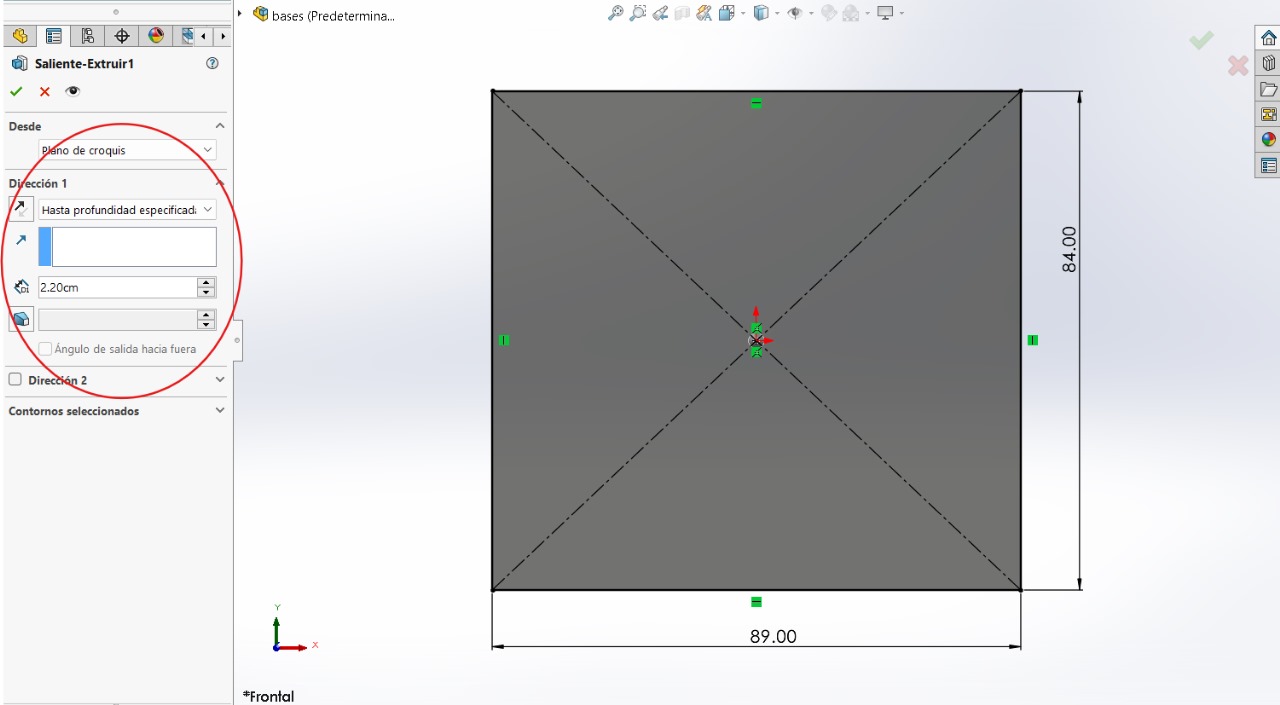
MIDDLE BASES
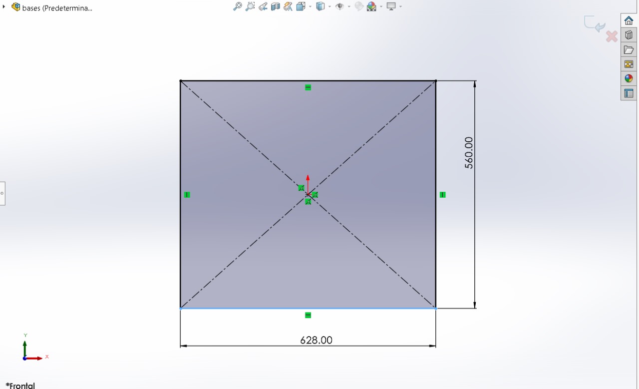
These parts will be the other two bases of the furniture
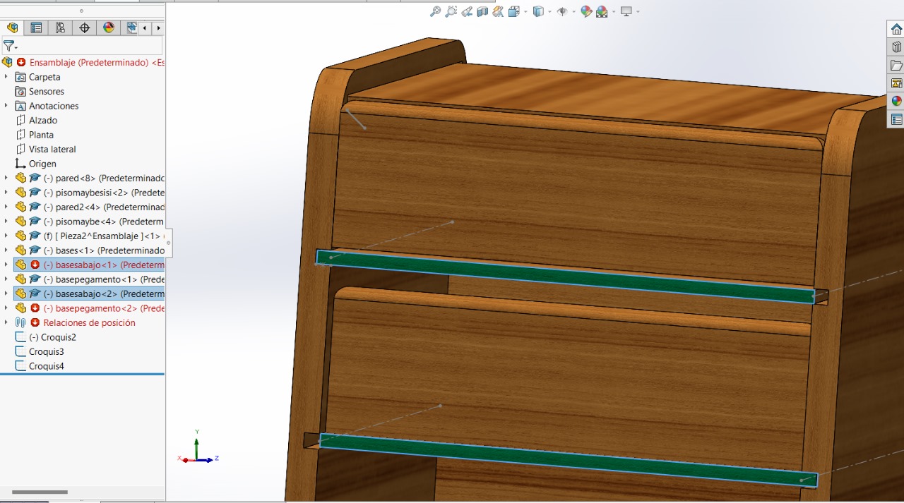
Sketch and Extrude Boss/Base
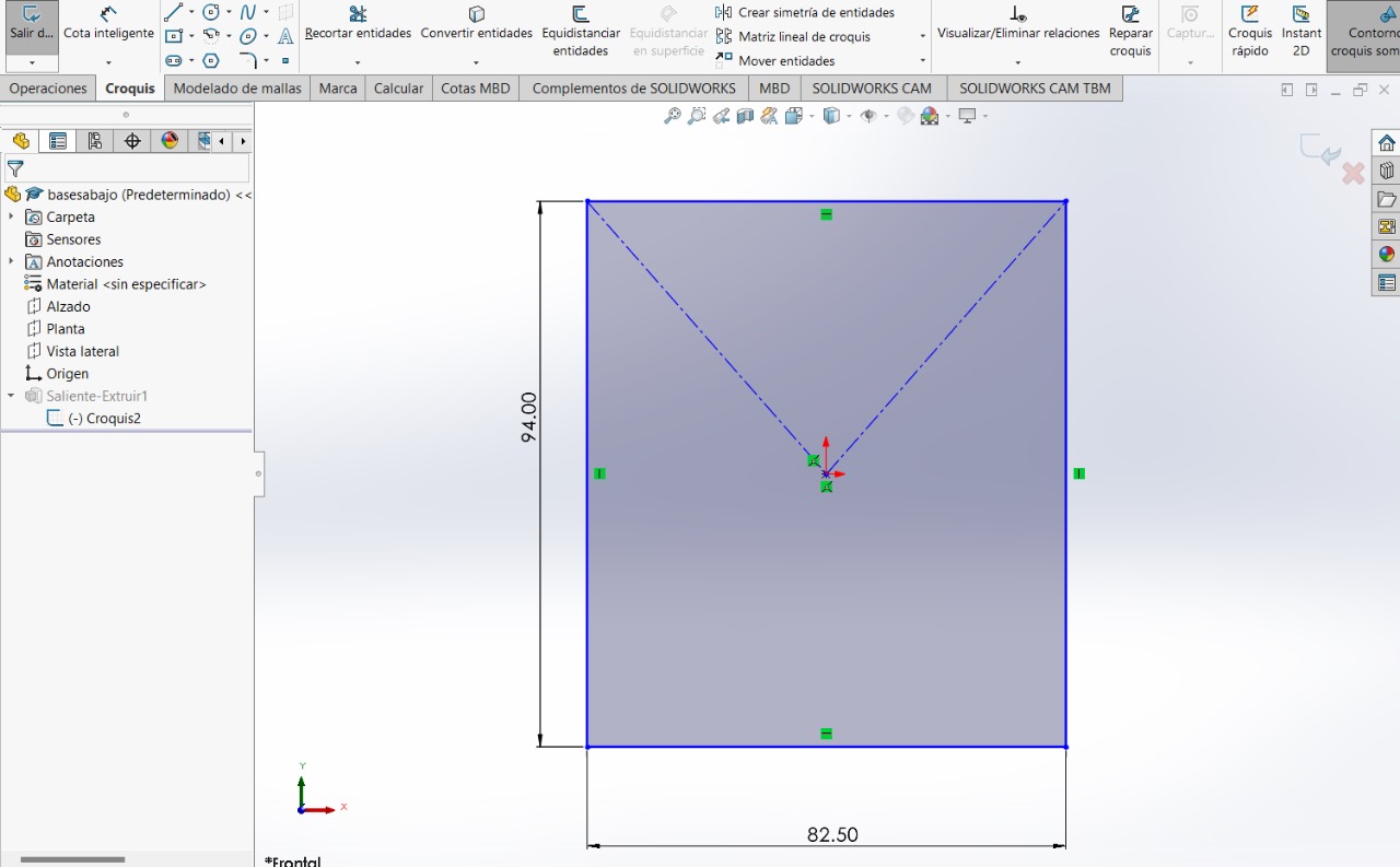
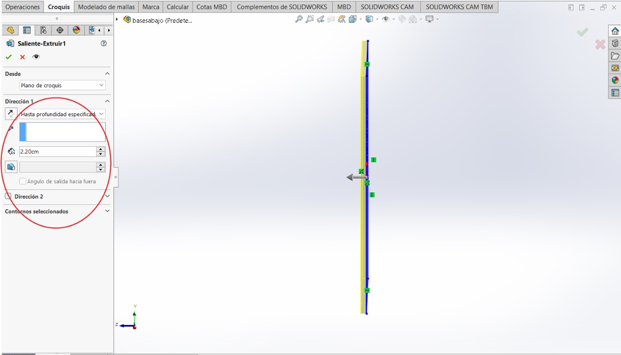
COVERS
These covers will be for moving the bases
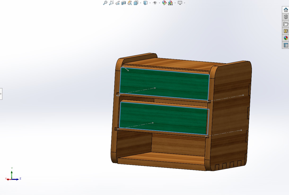
Sketch and Extrude Boss/Base
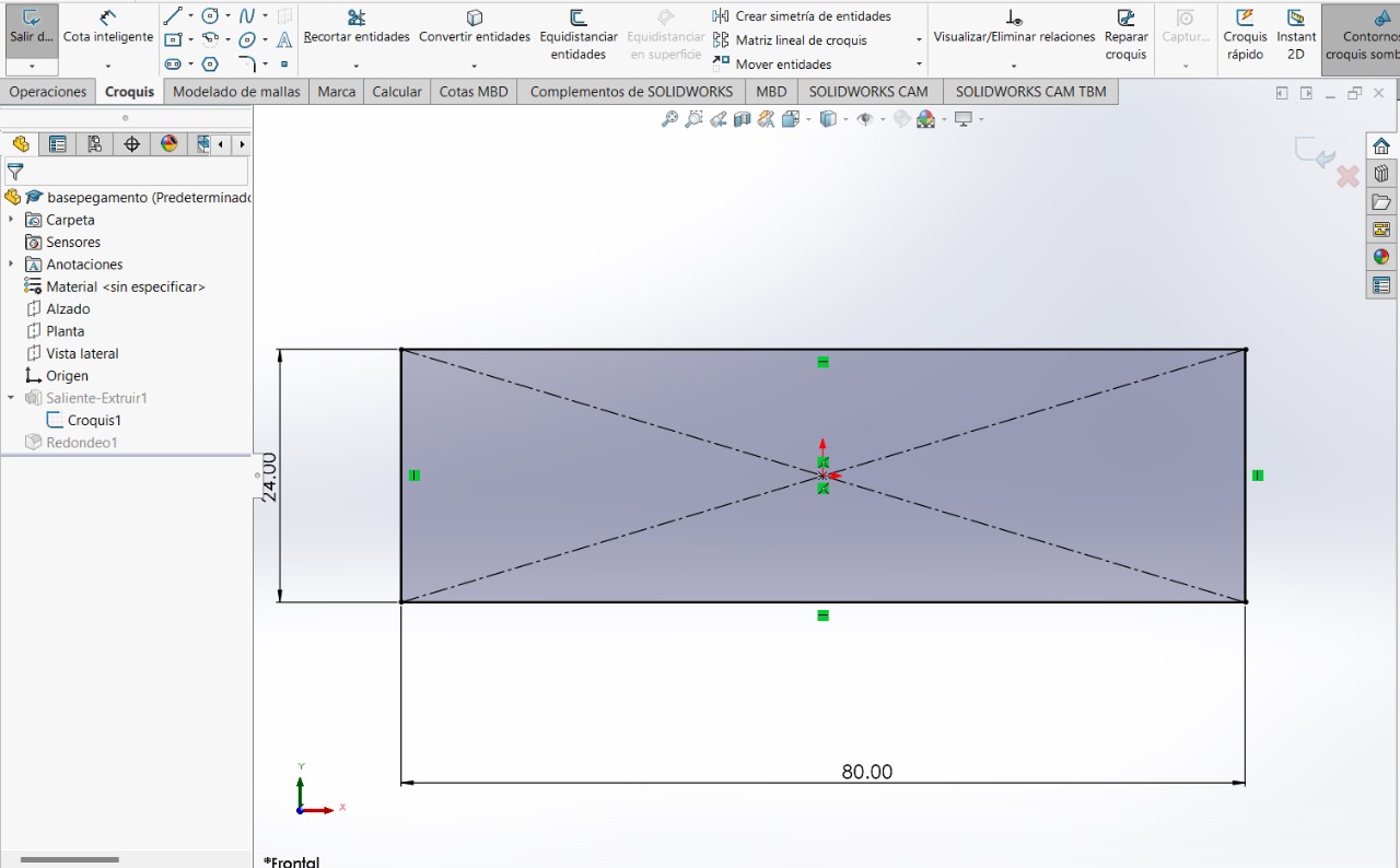
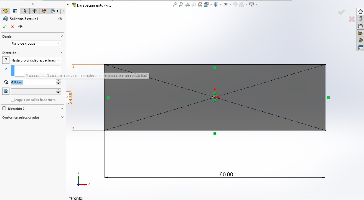
Sketch and Extrude Boss/Base
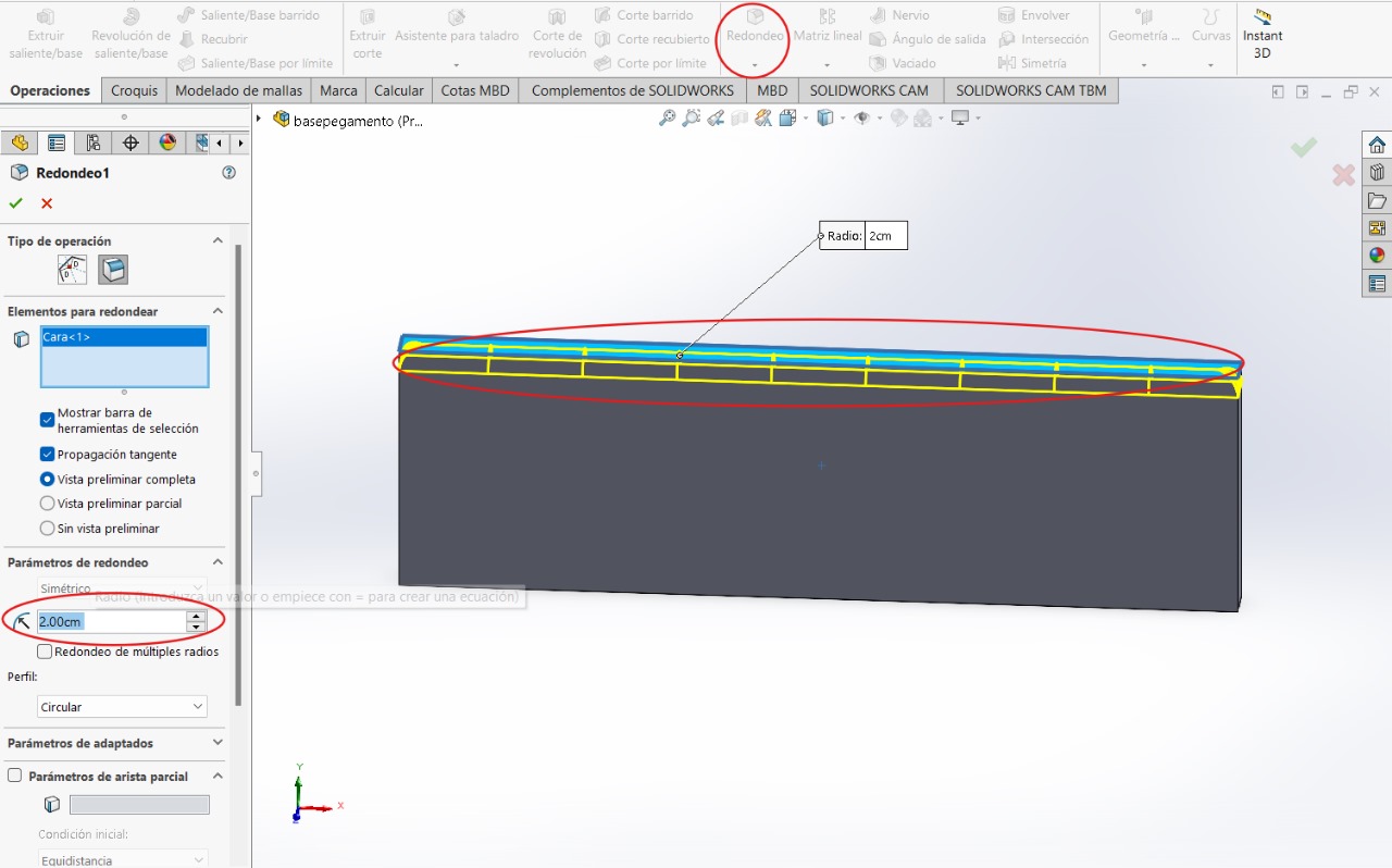
ERRORS FROM PARTS
I had to repeat most of the parts because Alberto Blanco - local evaluator from Puebla explained to me how joining the pieces would work. The same thing happened to me as in the 'laser cutter' week because I was creating parts with dimensions larger than the width of the material to be used. Also, when trying to change the dimensions of my pieces, it wasn't possible because they became distorted as they weren't parametric (without equations). I had to repeat them this way and with those dimensions


CORRECTIONS
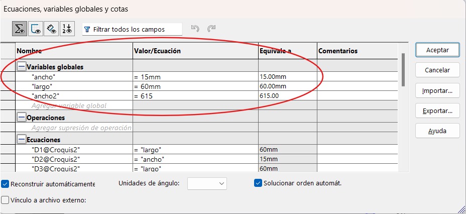
To start the corrections of the pieces, we will first start by creating the pieces and making them parametric. We will use equations. To create them, follow the following steps: "Alt - Tools - Equations - create names and values"
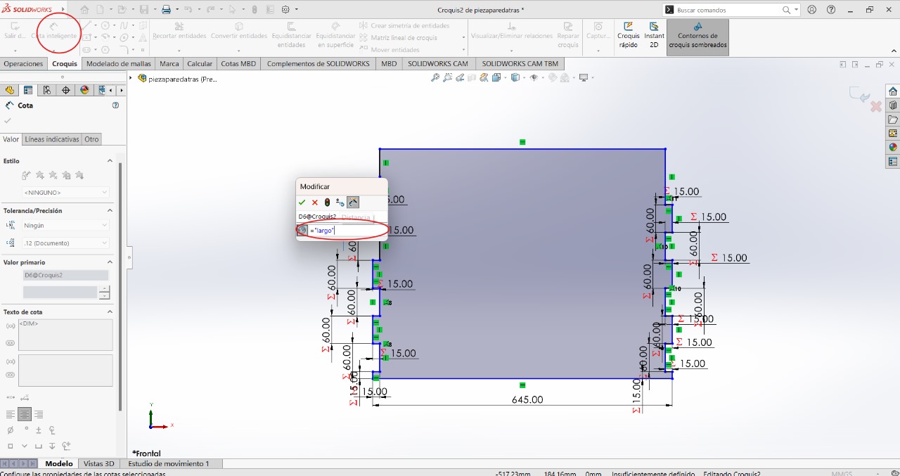
BACK PART
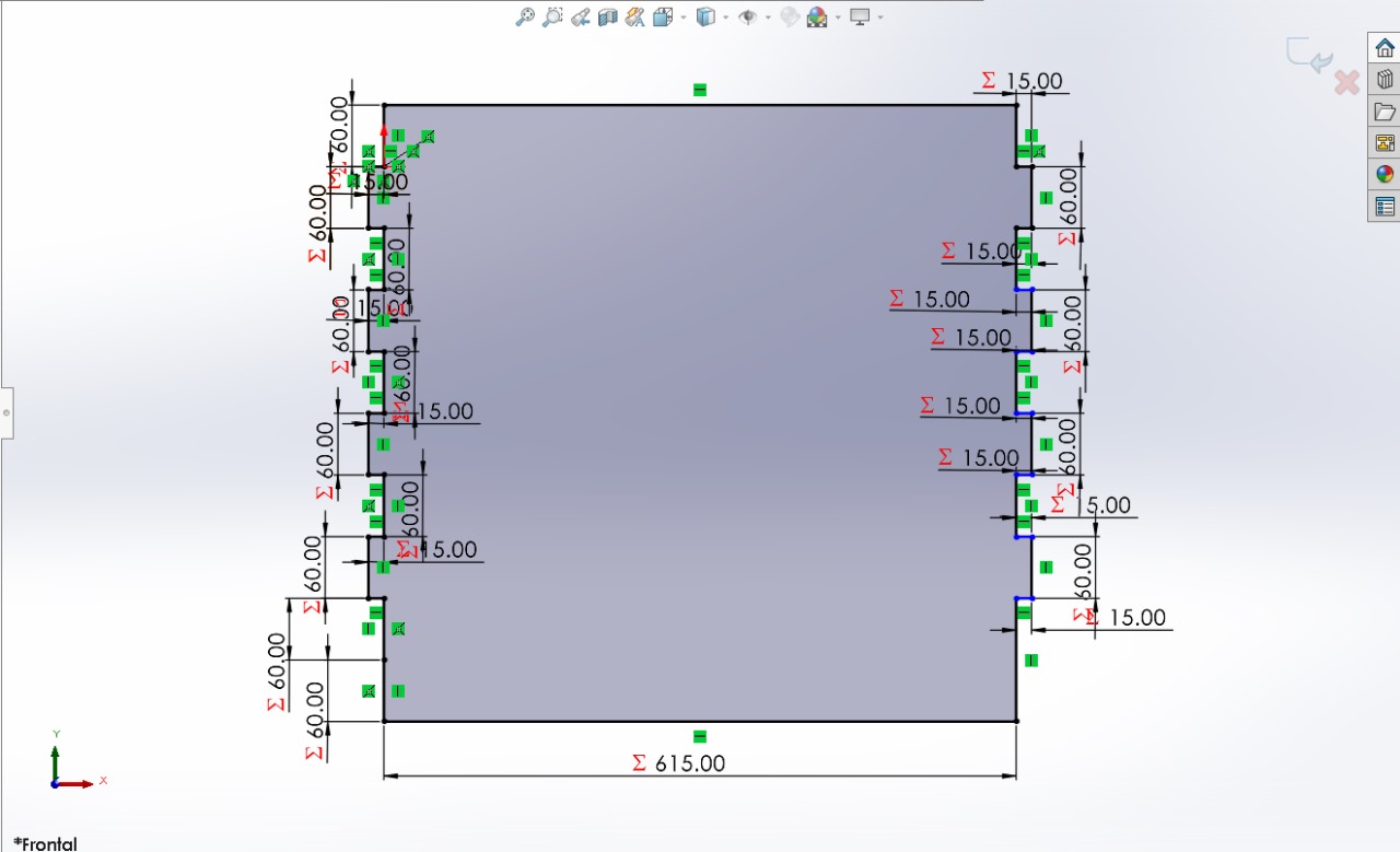
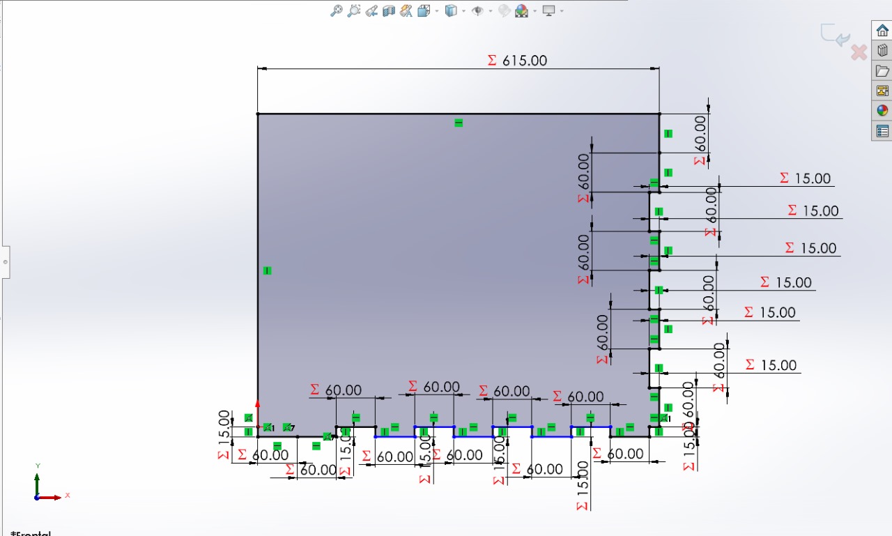
This way you can give values with the names you gave on the previous page
BOTTOM PART
LEFT RIGHT AND RIGHT SIDE
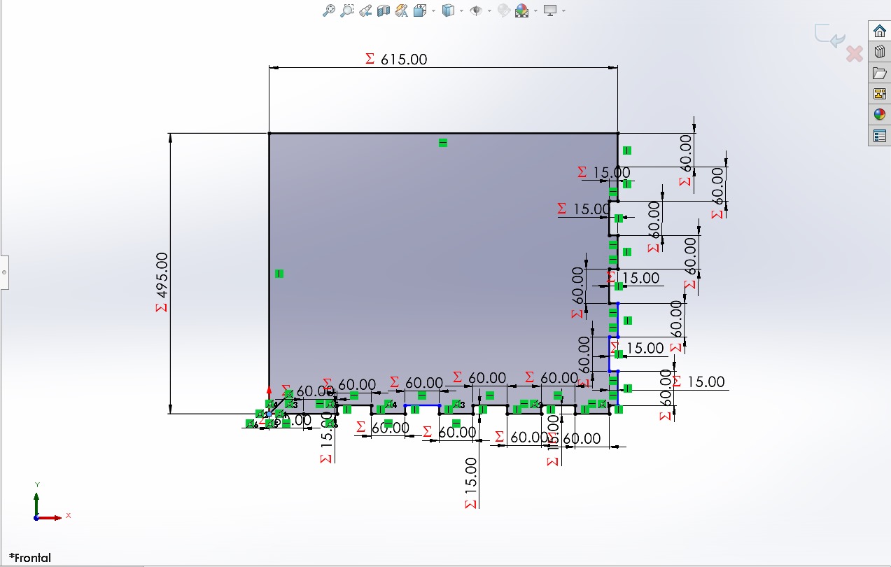
--------------------------------
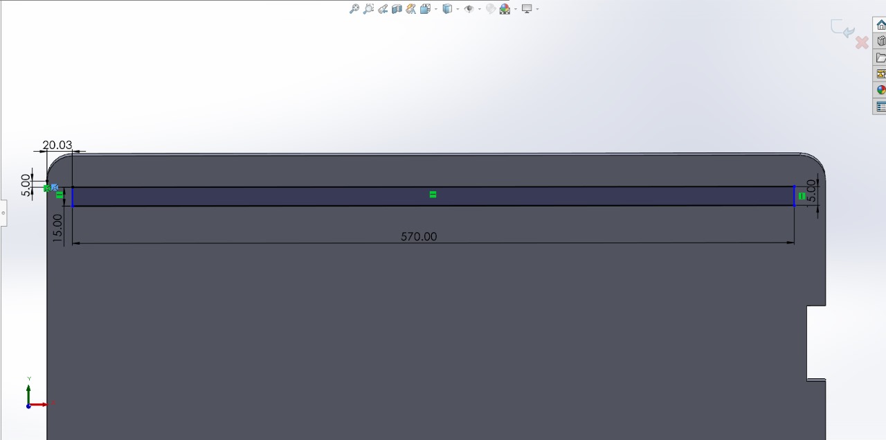
--------------------------------
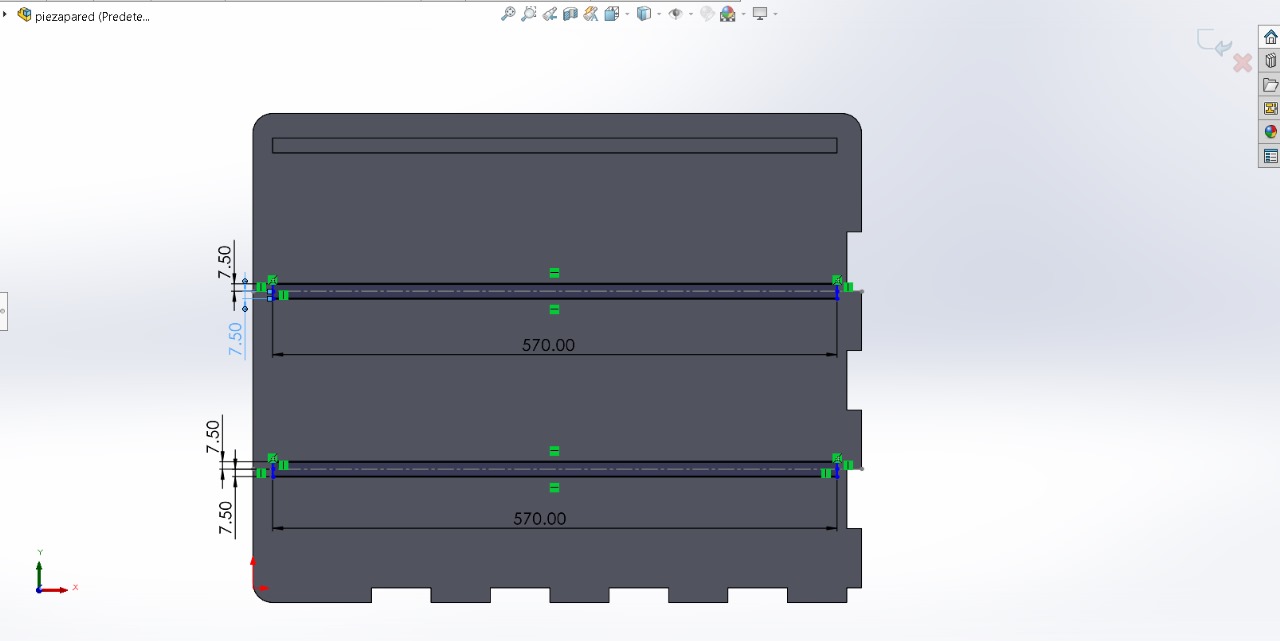
BASES
ASSEMBLY
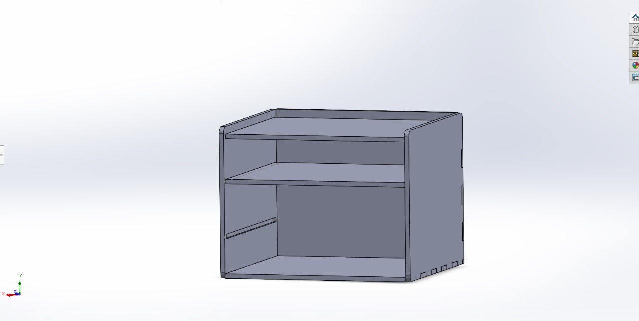
All the previous parts must be saved as '.stl' in order to use the followwing program
- VCarve Pro -

The first thing we will do is create a new file, and it will be to change some parameters that depend on the size of your wood as well as some parameters that we will select when using the machine. All the previous parts must be saved as '.stl' in order to use the next program

Next will be to import the parts that we previously saved as '.stl' into the file. You can select the parts with left click and you can move them by selecting them and selecting a part of the figure. "File - Import"
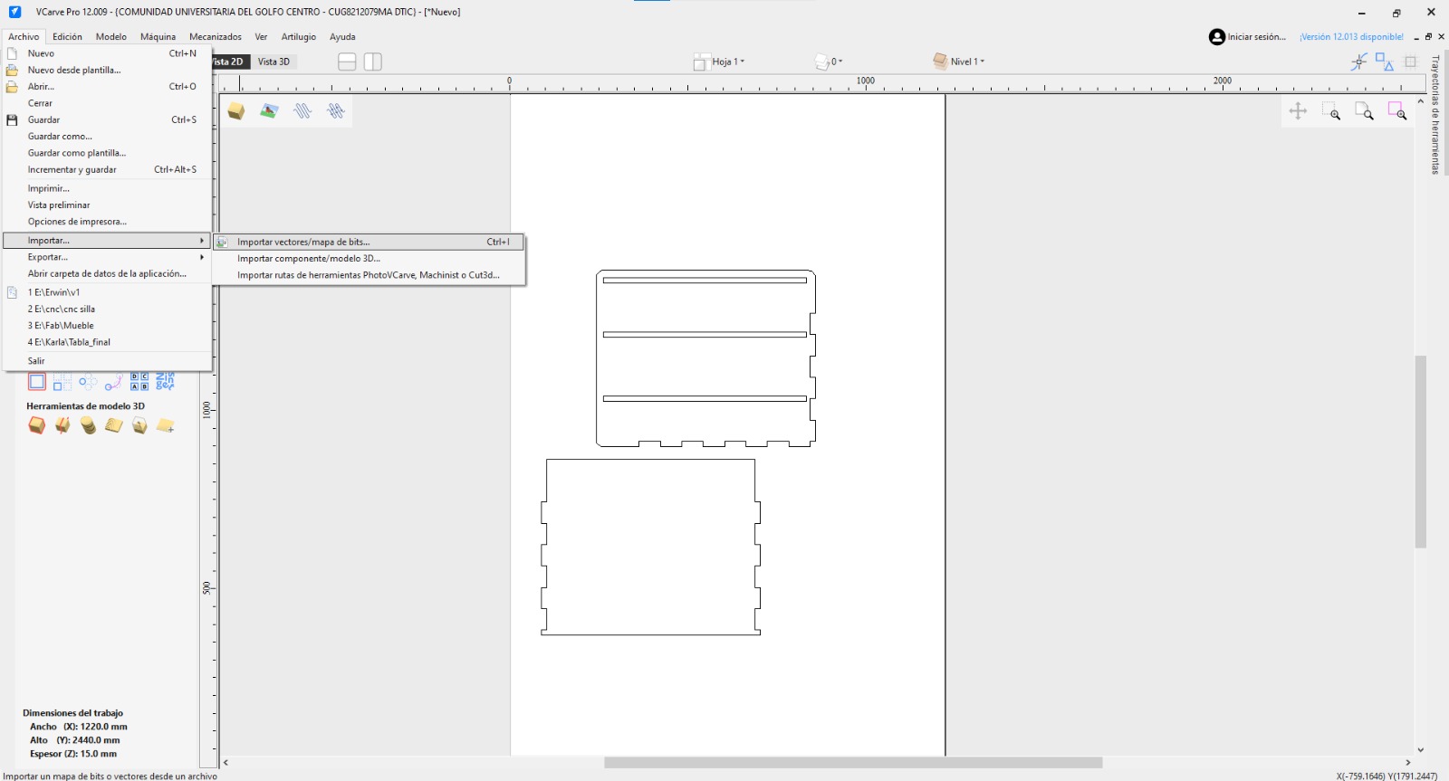
I arranged the images according to the table, using the "move selection" tool to the rightmost part of the table and others to the leftmost part of the table. I moved them by changing the 'x' or 'y' parameters
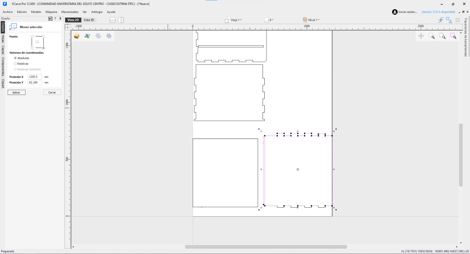
We will also use the 'join' tool so that it becomes just a single figure. We will also use the 'join' tool so that it becomes just a single figure. The figures that we will join as a single one will be only for those that are on the outside, and the figures that are on the inside will also be different from those on the outside. Each of these we must join together.
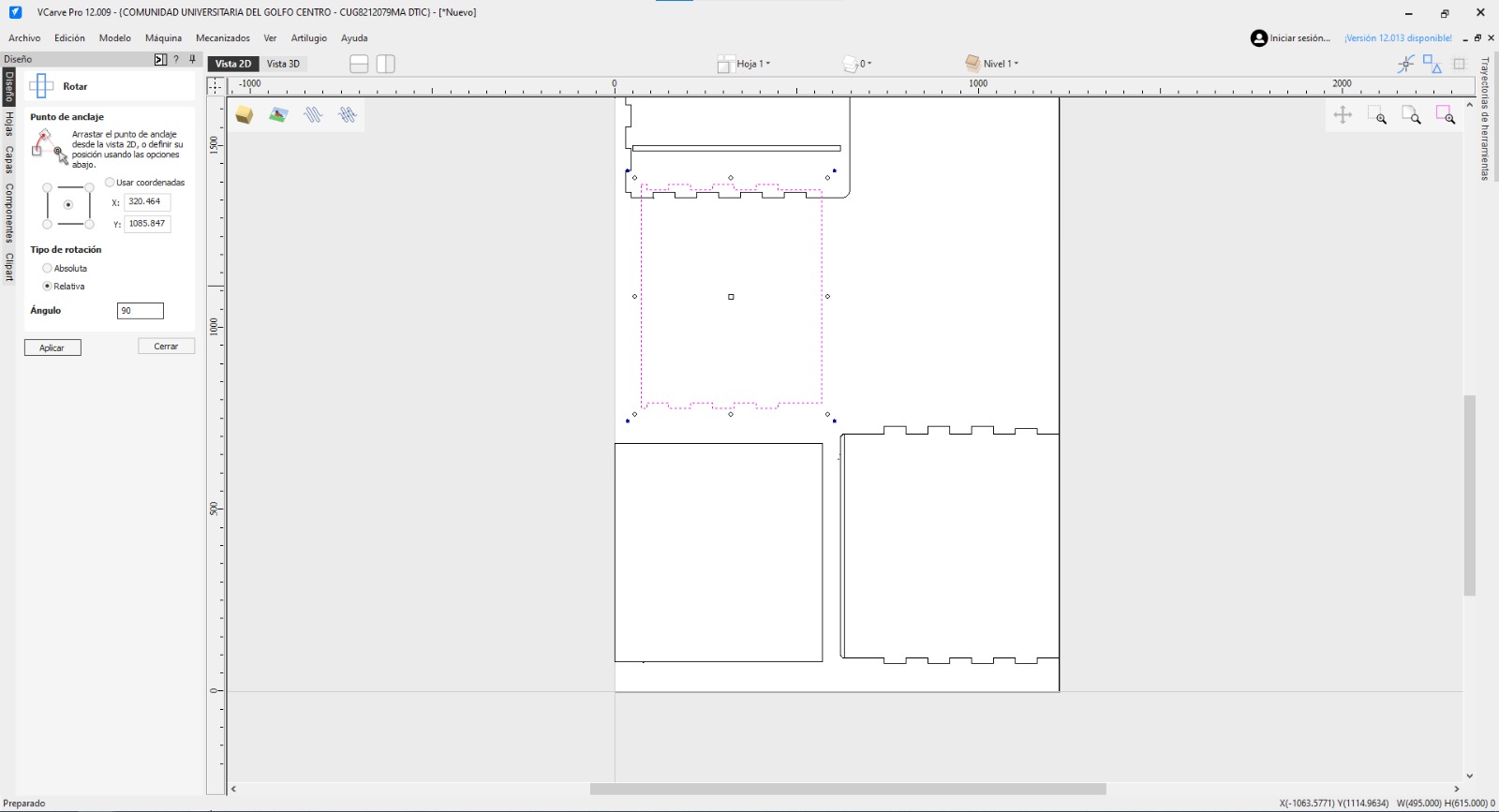
I was also able to change which part of the figure I'm going to cut without using more material with the 'rotate - relative - 90°' tool. This way I changed the side that I want to cut
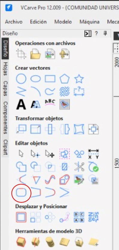
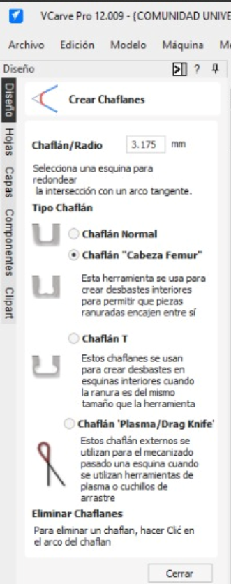
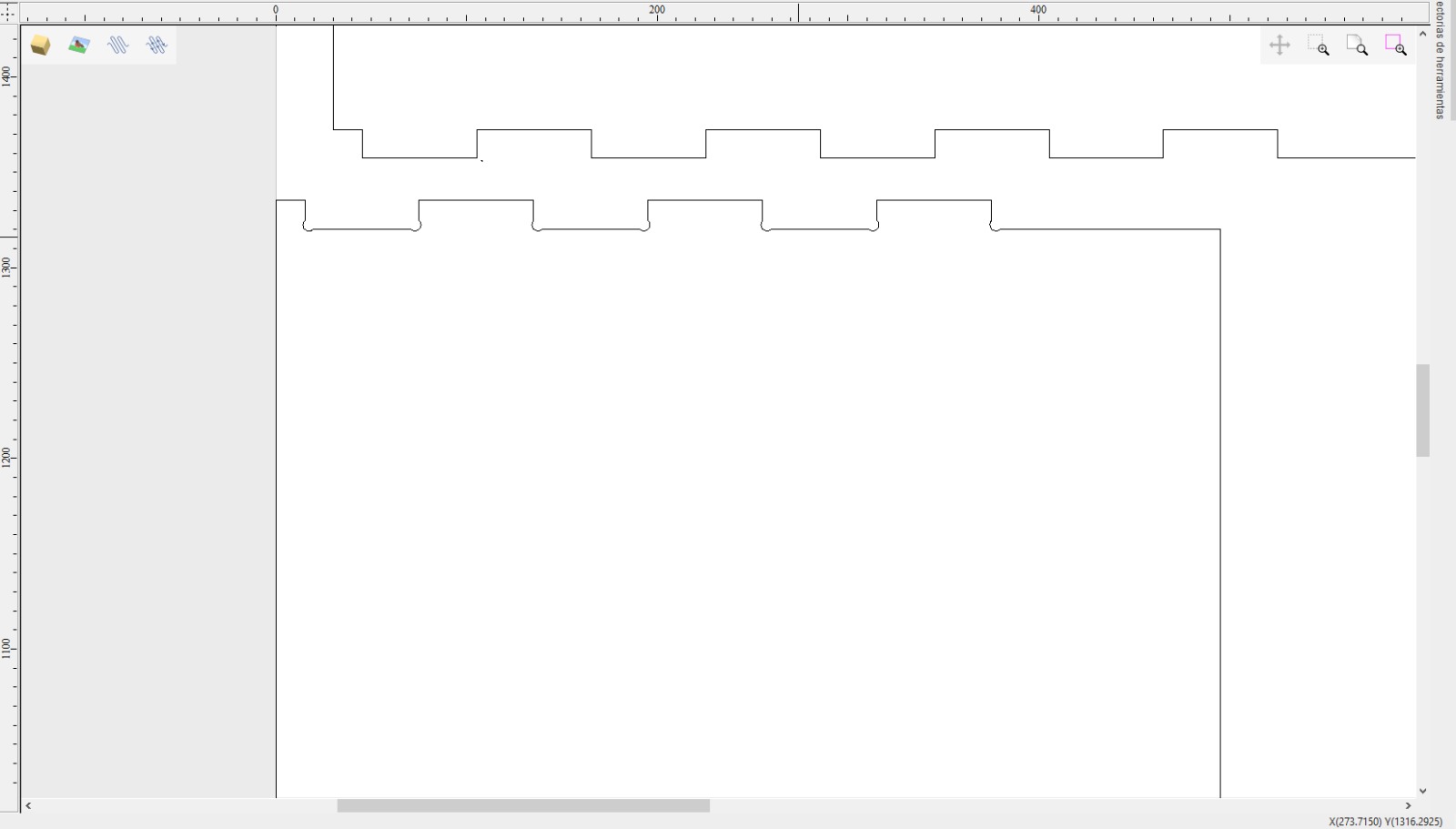
We will use the 'chamfer' tool to be able to join pieces more easily, we will place them strategically in this type of points
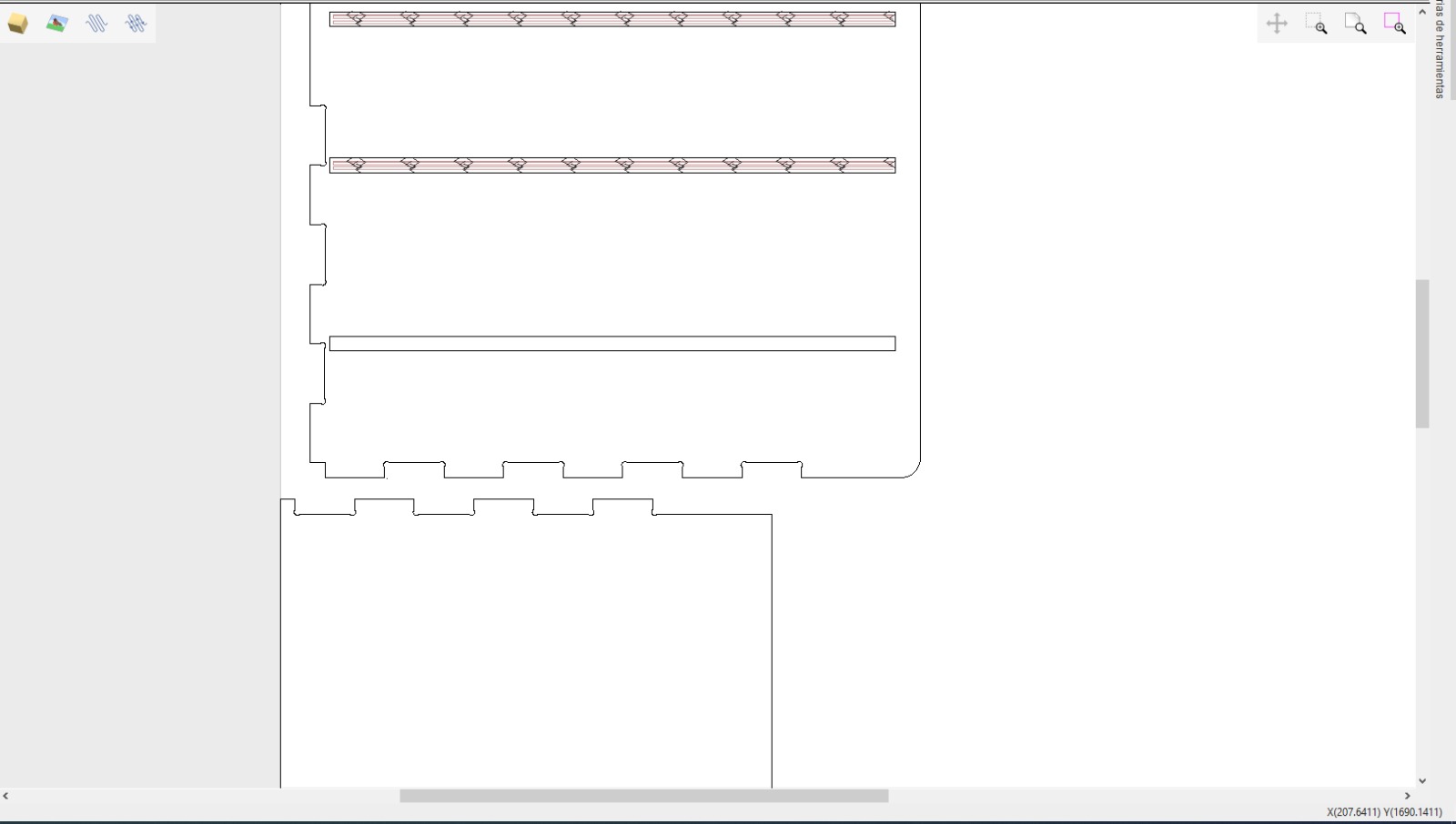
Finally, on the right side of the application there will be two options that we will use, which will be profiling and pocketing. As for profiling and pocketing, they will have the same configurations; however, the profiling will be calculated only for the parts that are on the outside, and the pocketing will be for the parts that are inside the main figure
The configurations for both profiling and pocketing will be the same
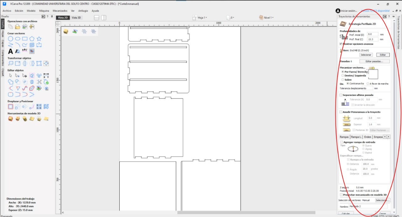
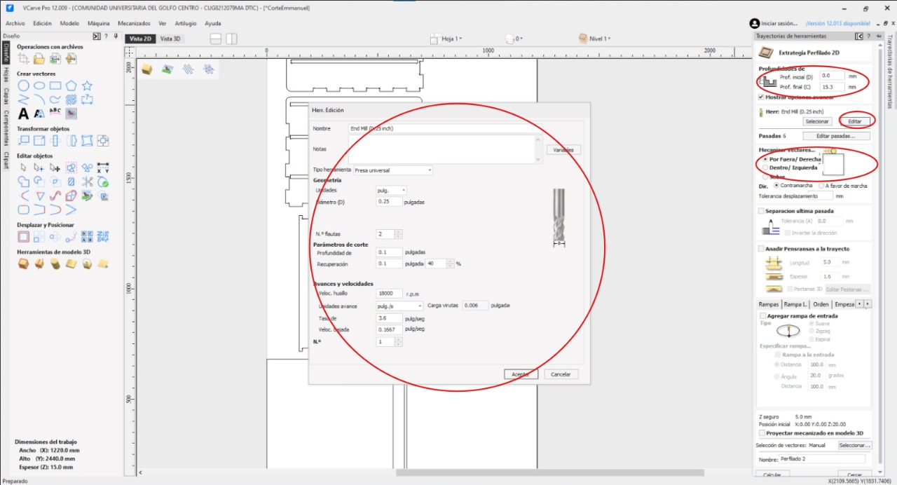
Finally, we will add 'tabs' to each of the figures. These will help us so that when the figure is finished cutting, they will not separate from the wood
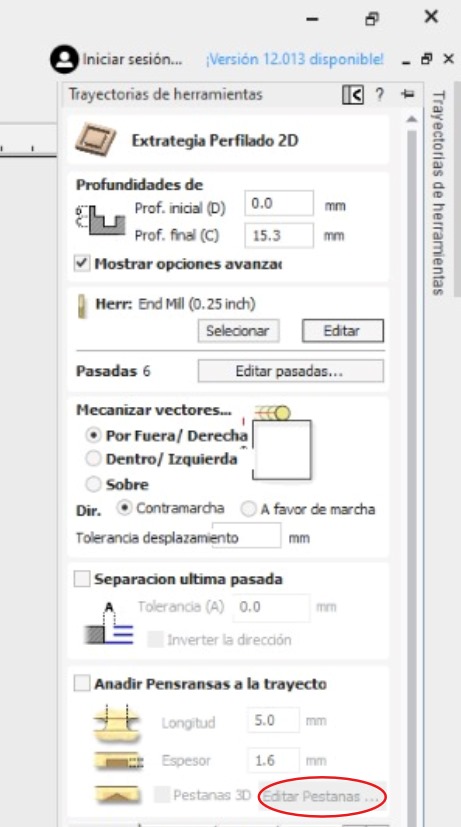
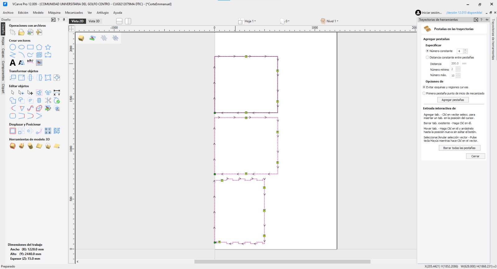
We will save the path with the option that is in the same part as the profiling and pocketing tools
- CNC MACHINE OPERATION STEPS -
The machine I used was: ASIA ROBOTICA - SHOP 1325
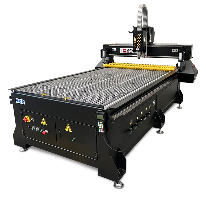
I will give the instructions I followed to be able to use the machine and make it cut:
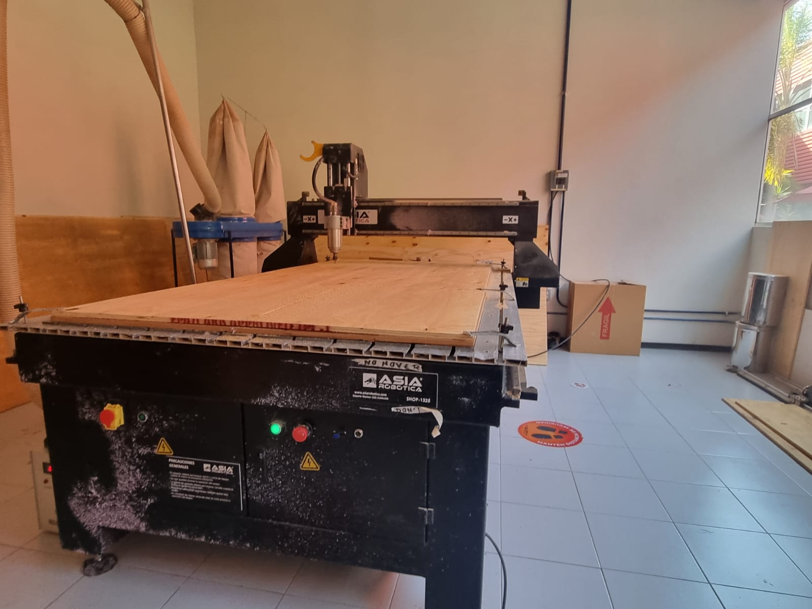
- Place the wood and safety locks.
- Turn on the machine by turning the red button and pressing the green button, then turn on the cooling system 'industrial chiller' and insert the memory.
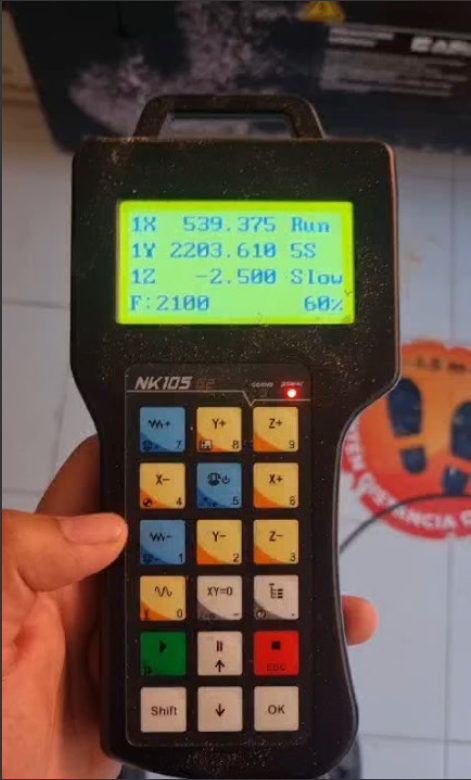
- Manage with the 'x', 'y' and 'z' coordinates to take the tip to the point previously placed in the program (you can do it faster or slower with the numbers '1' and '7'). If you still can't place the tip to the corner, you can make the movement slower with the 'shift - stepping (for faster) and log (slower)' button.
- When the tip is in the corner, press the xy=0 button and accept. At that moment the cutter will know that side is x=0 and y=0. For z, move the tip a little towards any side of the wood, lower it until it can make a mini cut when moved by hand (this should be slight, only until it doesn't get stuck when turning). When this point is found, press shift - z=0 on the control.
- Next, find your file with the button that looks like a half tree, above the red 'esc' button. Search for your file with the arrows, load it and select it.
- When everything is ready, start with the green button.
Recommendations:
- Keep your finger on the pause button in case something unexpected occurs during your cuts.
- You can increase the speed if your figure cuts behave as they should.
VIDEO:
When the machine finished cutting, I removed my pieces from the main wood and went to a machine that helps me sand the pieces
FINAL RESULT:
