5. 3D SCANNING AND PRINTING
- For this week, our global and local teachers asked us to design and 3D print an object that cannot be made subtractively, and as a second task was to scan an object and we could optionally print it.
- GRUPAL ASSIGNMENT -
Week 5 - 3D SCANNING AND PRINTING
- 3D SCANNING -
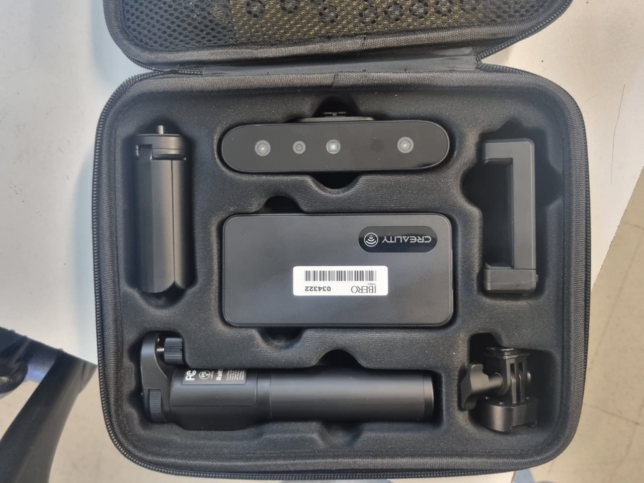
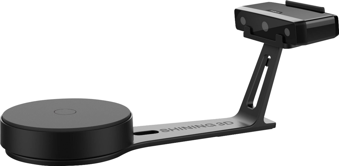
To start this week, I had several setbacks but I will document each of them. The first scanner I used was the 'EinScan-SE' and I used a Funko POP figure to scan.

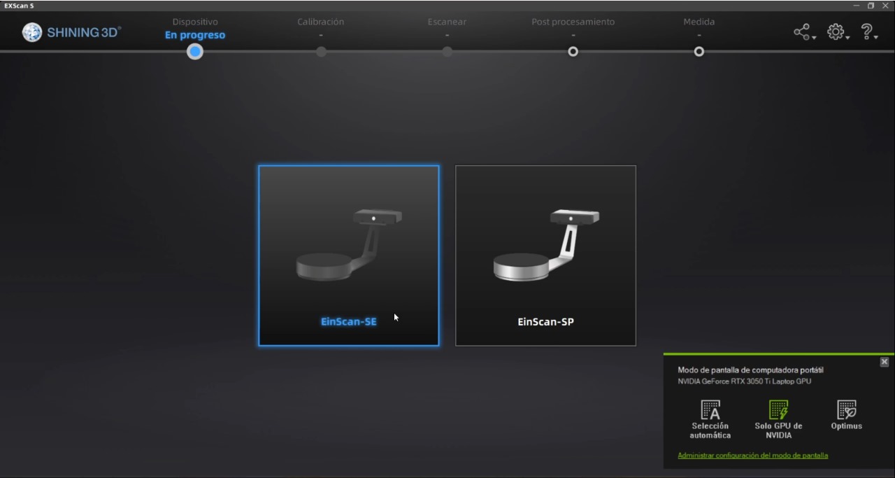
The next step was to calibrate the 3D scanner, selecting our scanner model as the first step
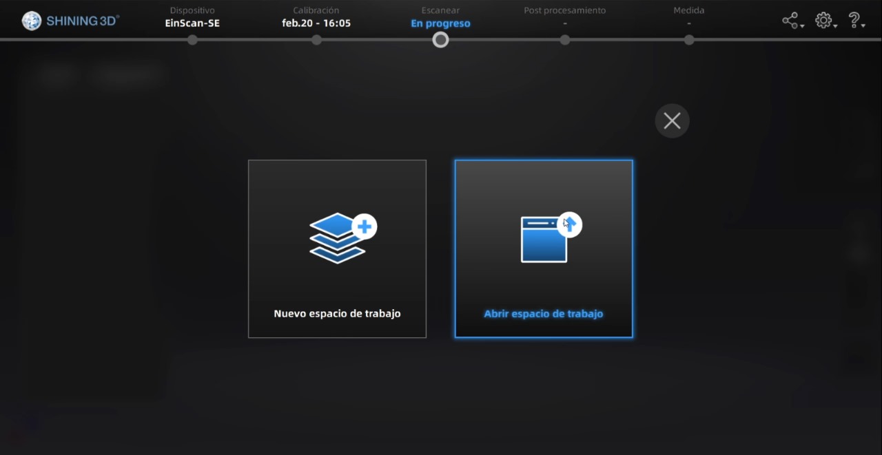
You open a new workspace where you will save the file when the 3D scan is complete
Now we will begin with the machine calibration, we will follow the images provided by the application to complete the three points.If you can see the images clearly, you can notice that you must change the position of the points palette depending on what it asks for
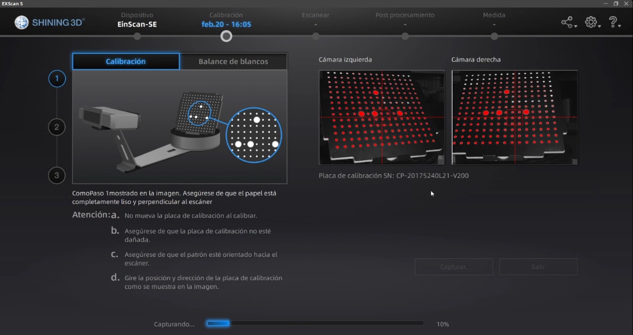
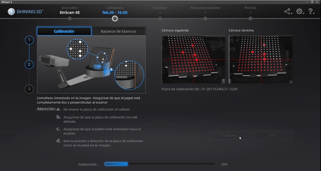
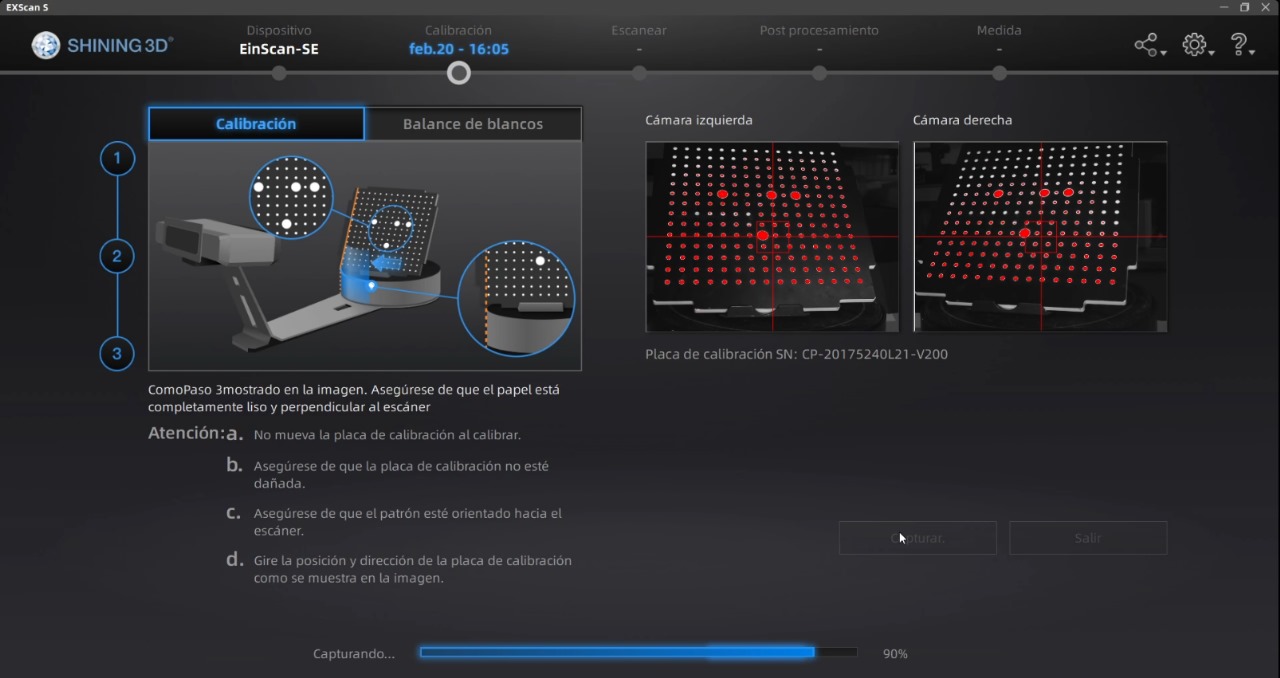
Another step will be to use a white sheet to complete the 'white balance' step
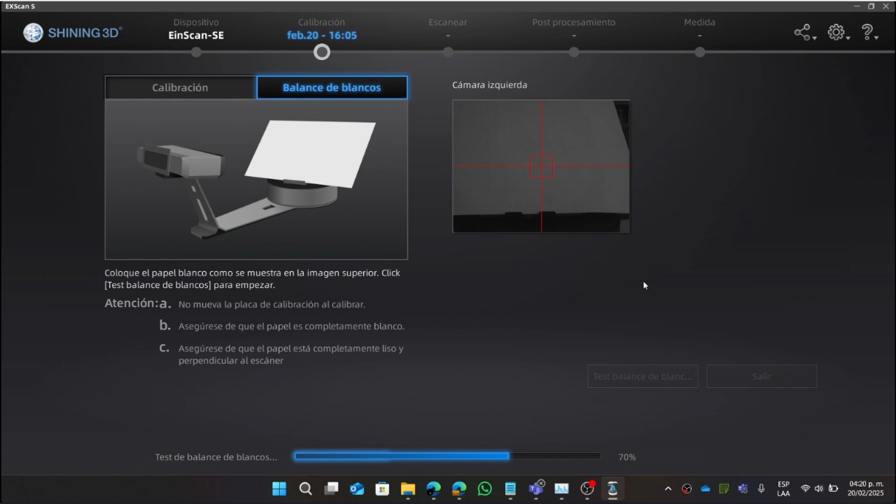
After completing the calibration steps, you can place the figure you want to scan. And you will click play to start. Although this is wrong, we will continue with this configuration, later I will tell you what things to change to improve the scanning
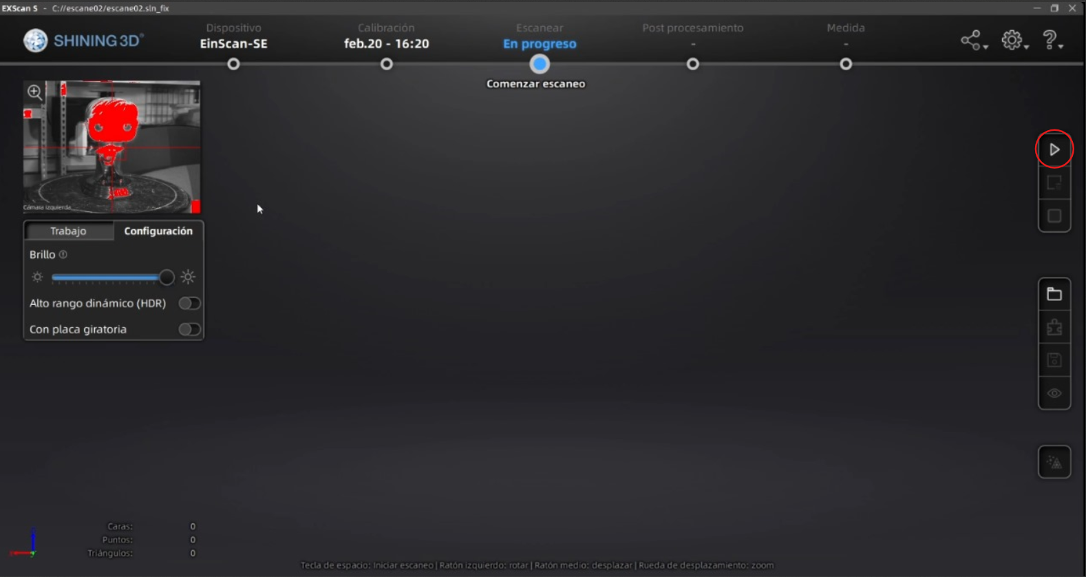
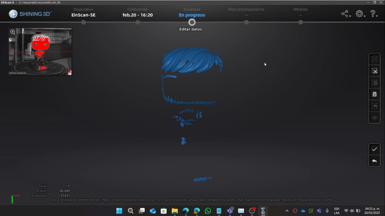
The scan didn't come out in the best way. To improve it, the local teacher Oliver Ochoa told me that the figure was too shiny and it would help to have more clarity if I put talcum powder on it to make it more opaque and improve the image. He also mentioned that I wasn't activating certain functions - you can notice this because in the image you can only see the first face of the figure. With the following image, you will see the necessary configurations that are needed for the complete figure
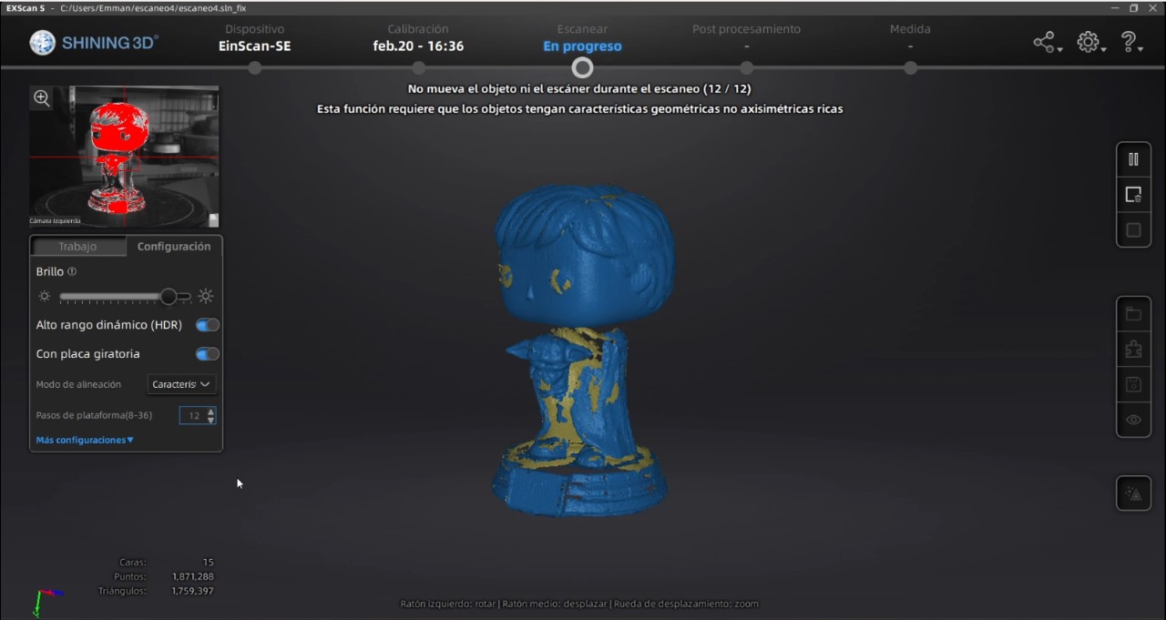
With the help of the configuration, the figure was more noticeable but still couldn't capture the entire figure. The teacher told me that it could have been because of the Funko POP, as its head and body moved each time the base rotated, which prevented the figure from being saved properly. But he mentioned that there was another scanner that was better for these types of more detailed figures, wich is the following:
With the software and the camera connected vsia USB to the computer, only the camera is recognized. This time I tested which way was the best option for scanning (trial and error), with the following configuration being the one that worked for me to scan my figure, the necessary configuration for this figure is the following:
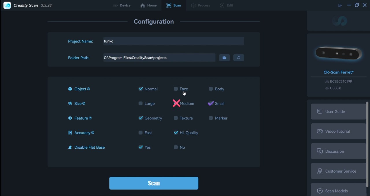
For the scan to come out well, it's necessary that the area where you're going to scan is clear, because the camera often captures other things. It's also recommended that you always stay in the 'optimal' zone that the software indicates. In my case, the camera comes with a tripod that helps hold the camera, but since I put the figure on a table and wanted the figure to have the most detail, I removed the tripod and just held the camera so it could have more up and down movement
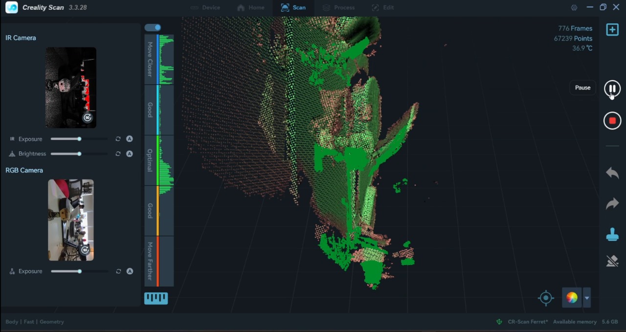
This is how the figure scanning finished:
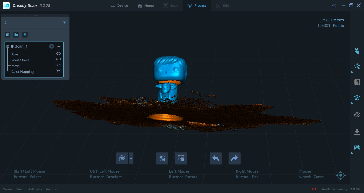
As you can see, the figure ended up with holes and it's necessary to cover them with the following configurations, we will also change certain parameters such as quality, model data (file size) and smooth
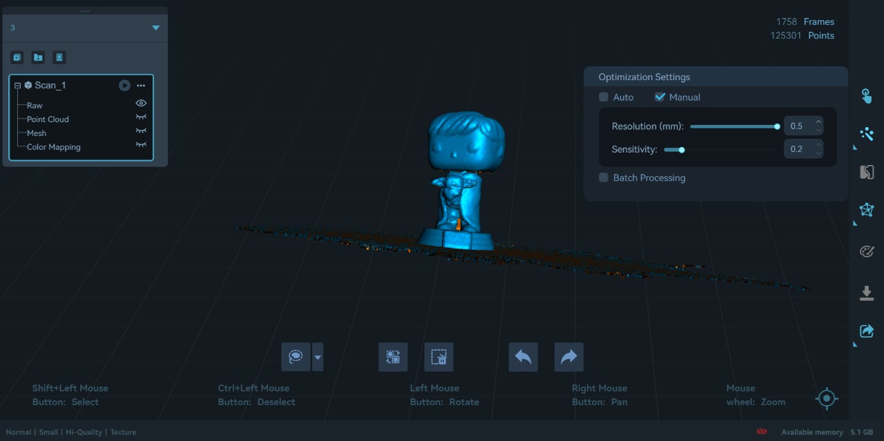
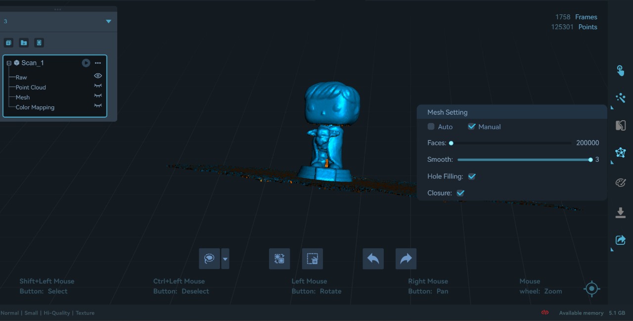
We will export the image with the .obj extension
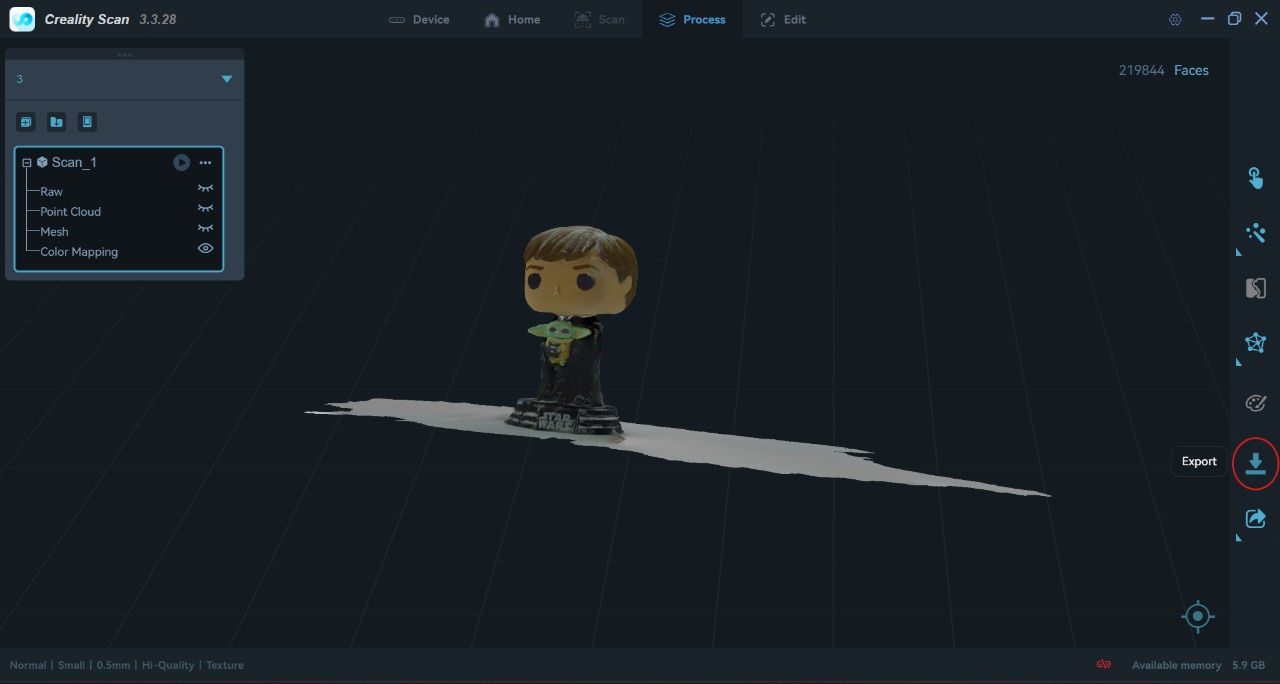
Here you can download the image: FunkoPOP.stl
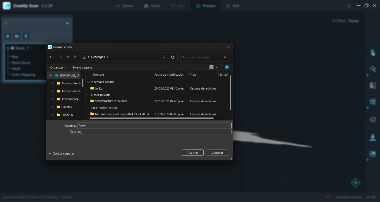
The 3D scanner also copied the table. To be able to eliminate it/edit the 3D figure, we can use the TinkerCad application.

To start we need to create a new project in "3D Design"
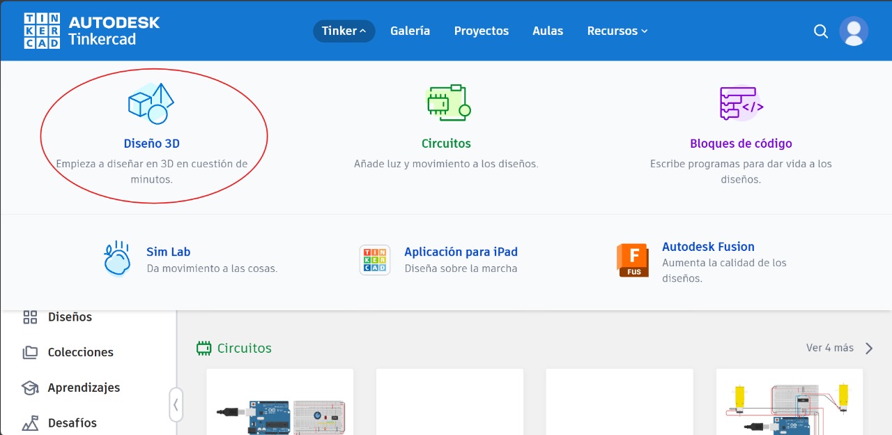
The file was too large to export in my case, but there is a solution with SolidWorks. We will have to open the file in SolidWorks and change the extension within the application
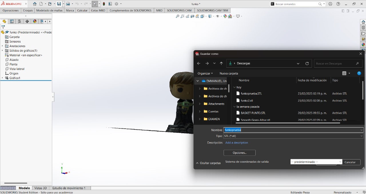
In my case, when changing the extension to ".stl", its size was reduced, which means we can now use TinkerCad. Now we will import our file, and with the help of basic shapes like the square, we can eliminate parts that we don't want. We can change the position (up, down, left, right) and size of the square that we place on the plane
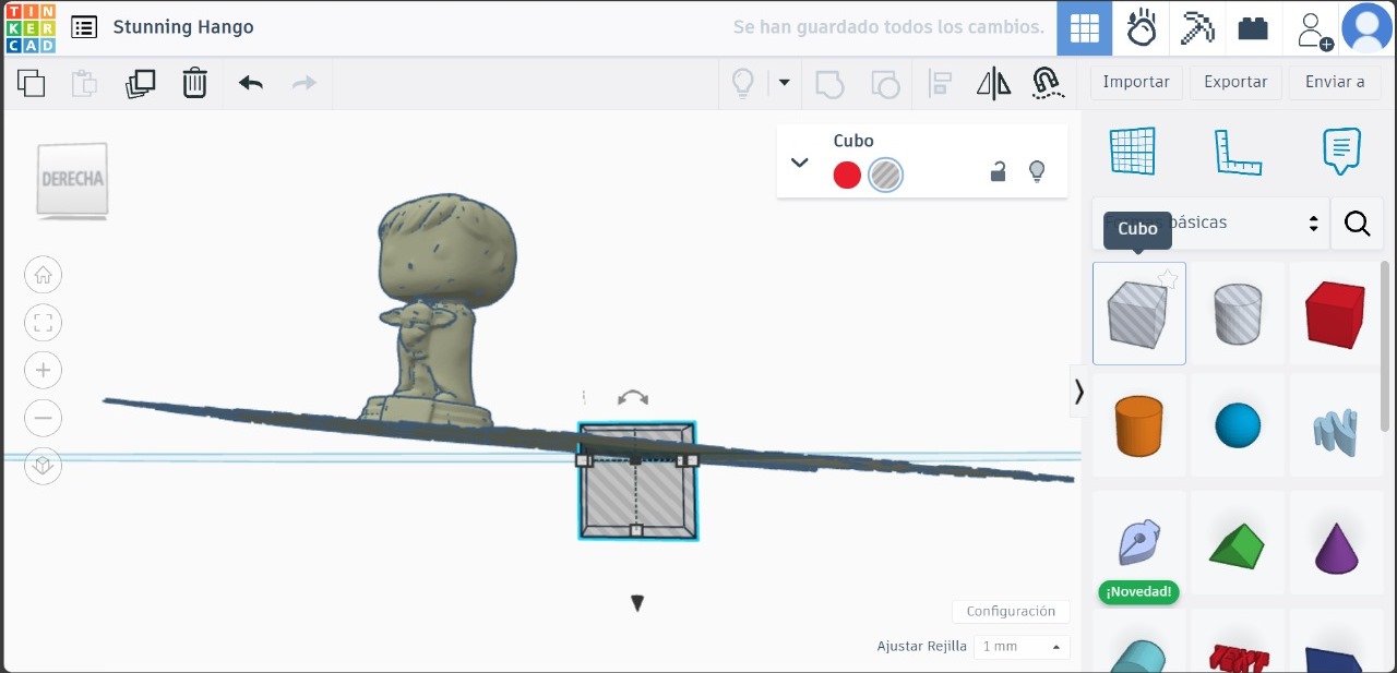
And to eliminate the parts of the figure that we don't want, with the help of the "SHIFT" key, we will click on the 3D figure and the square that we have made, as shown in the image
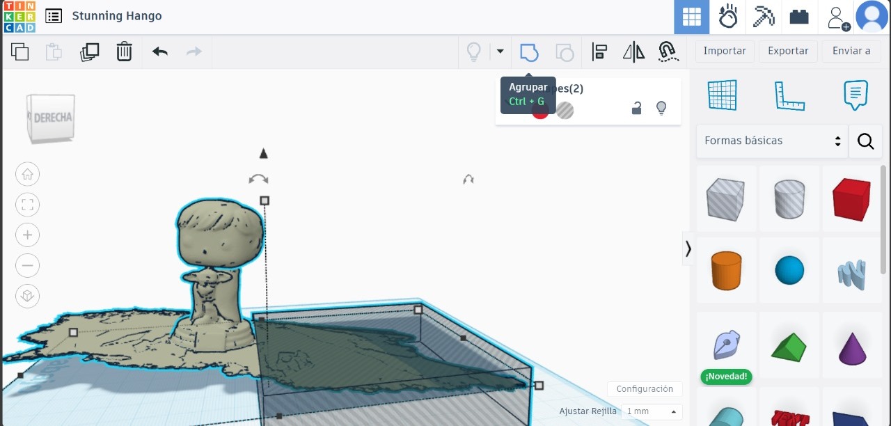
This is the final result, as final export them in ".stl":
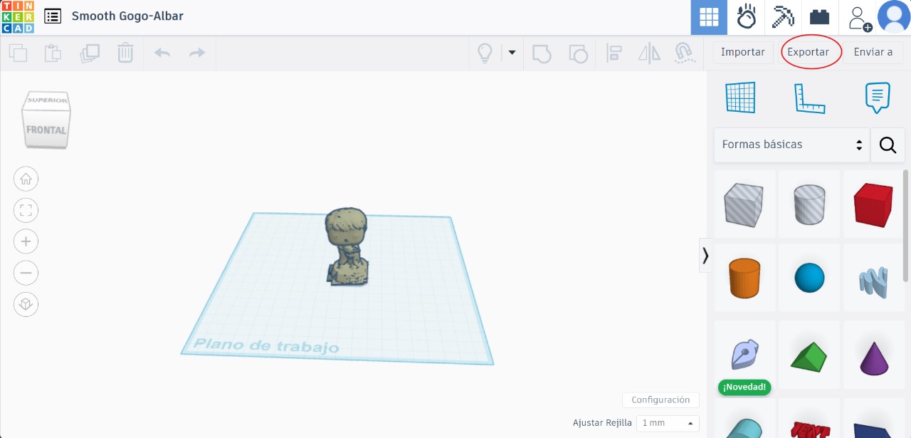
Here you can download: FunkoPOP.stl
To be able to print, certain parameters of the figure and within the application need to be changed.
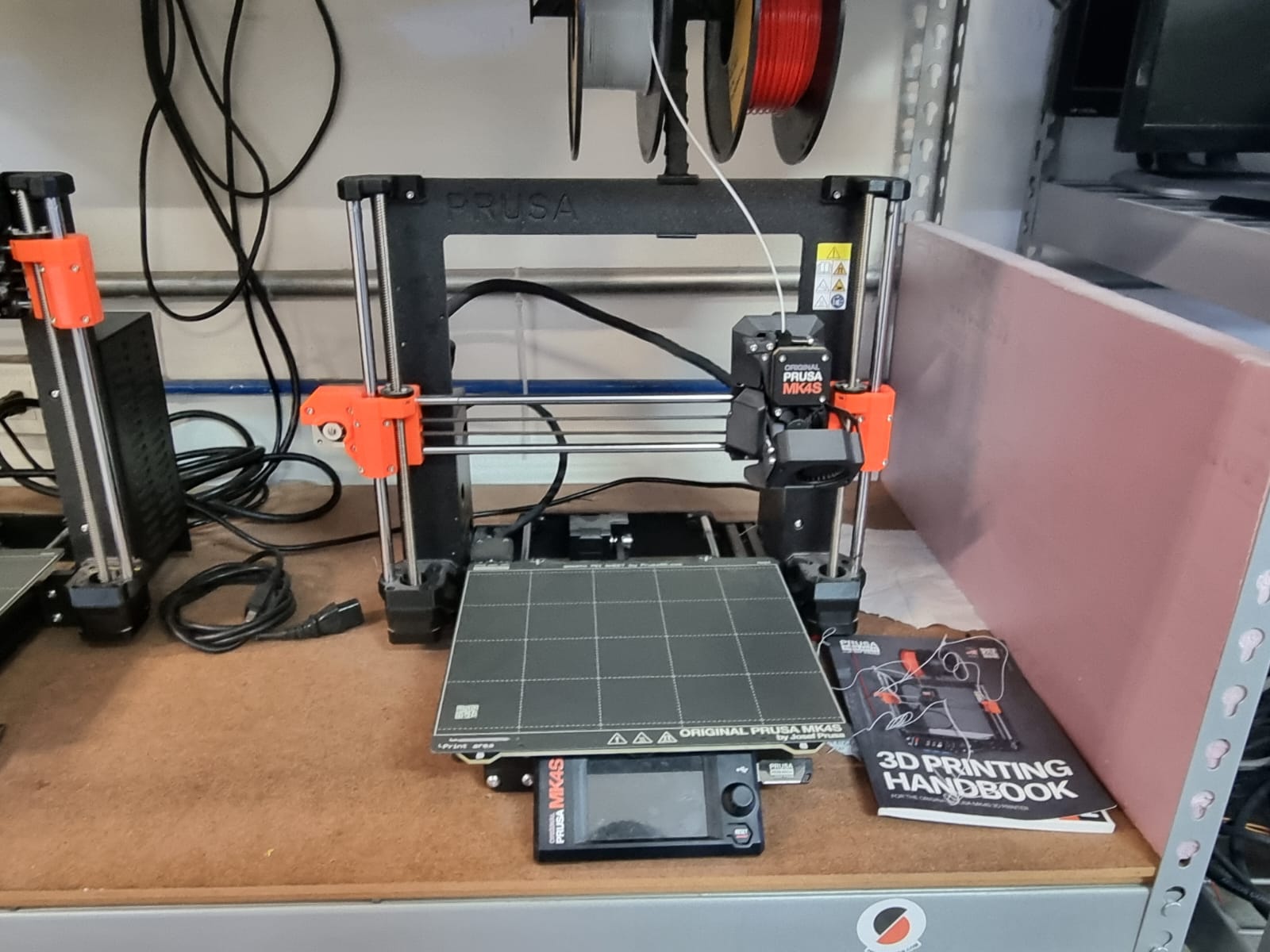
3D printer Prusa MK4S
Within the application, we will open our project and change certain parameters inside the application. We will open the file that we saved as ".stl" in this way
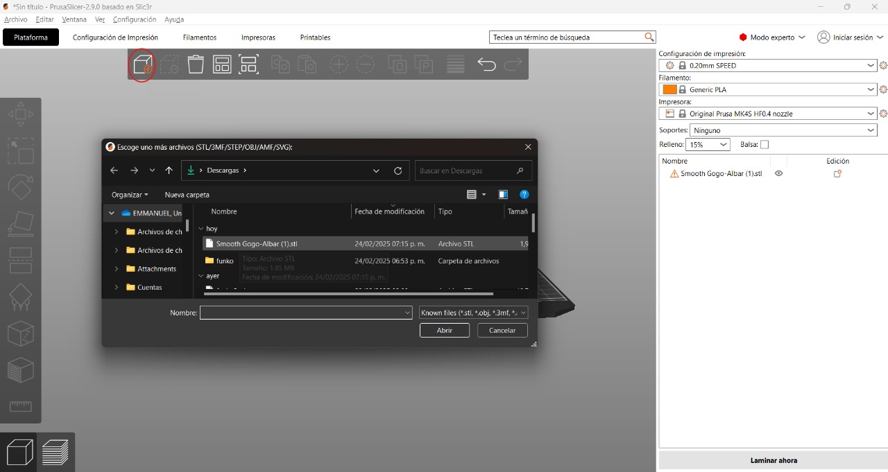
Within the application we can move the figure, make it larger among other things. I recommend trying each of the options to test what each one does
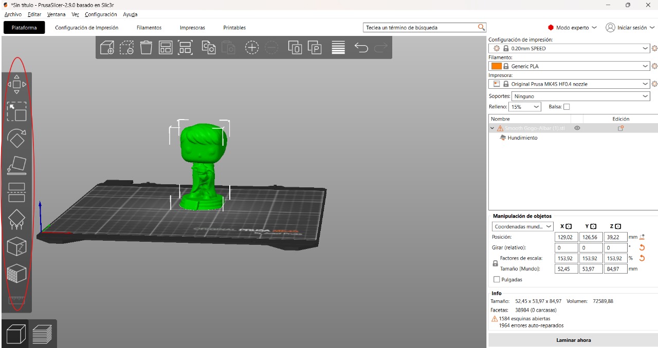
The only thing left is to adjust some parameters that in the case of my figure are necessary.
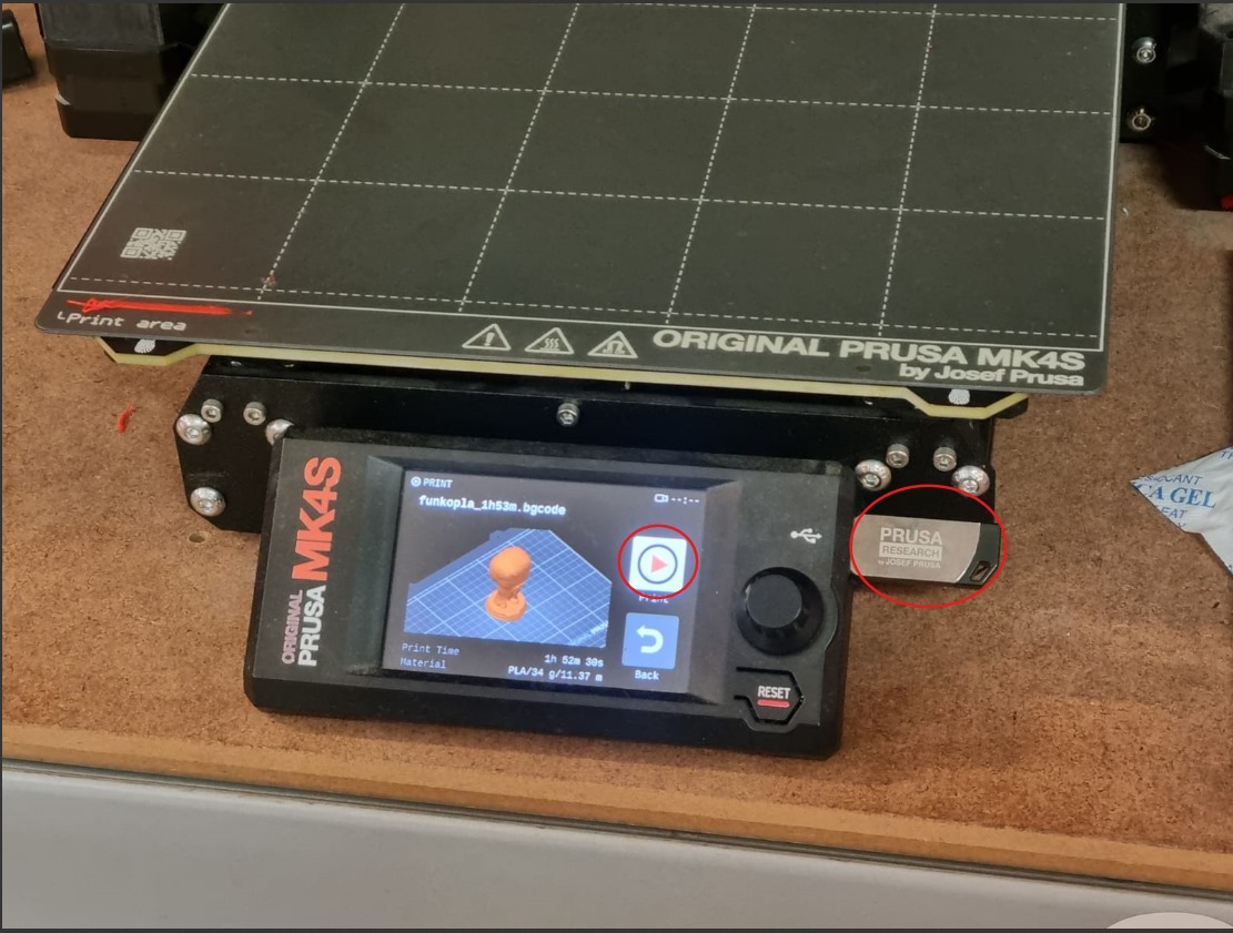
The 3D printer's memory will be used to save it, and the 3D printer will identify the new file inside it. It's as easy as just pressing "play"
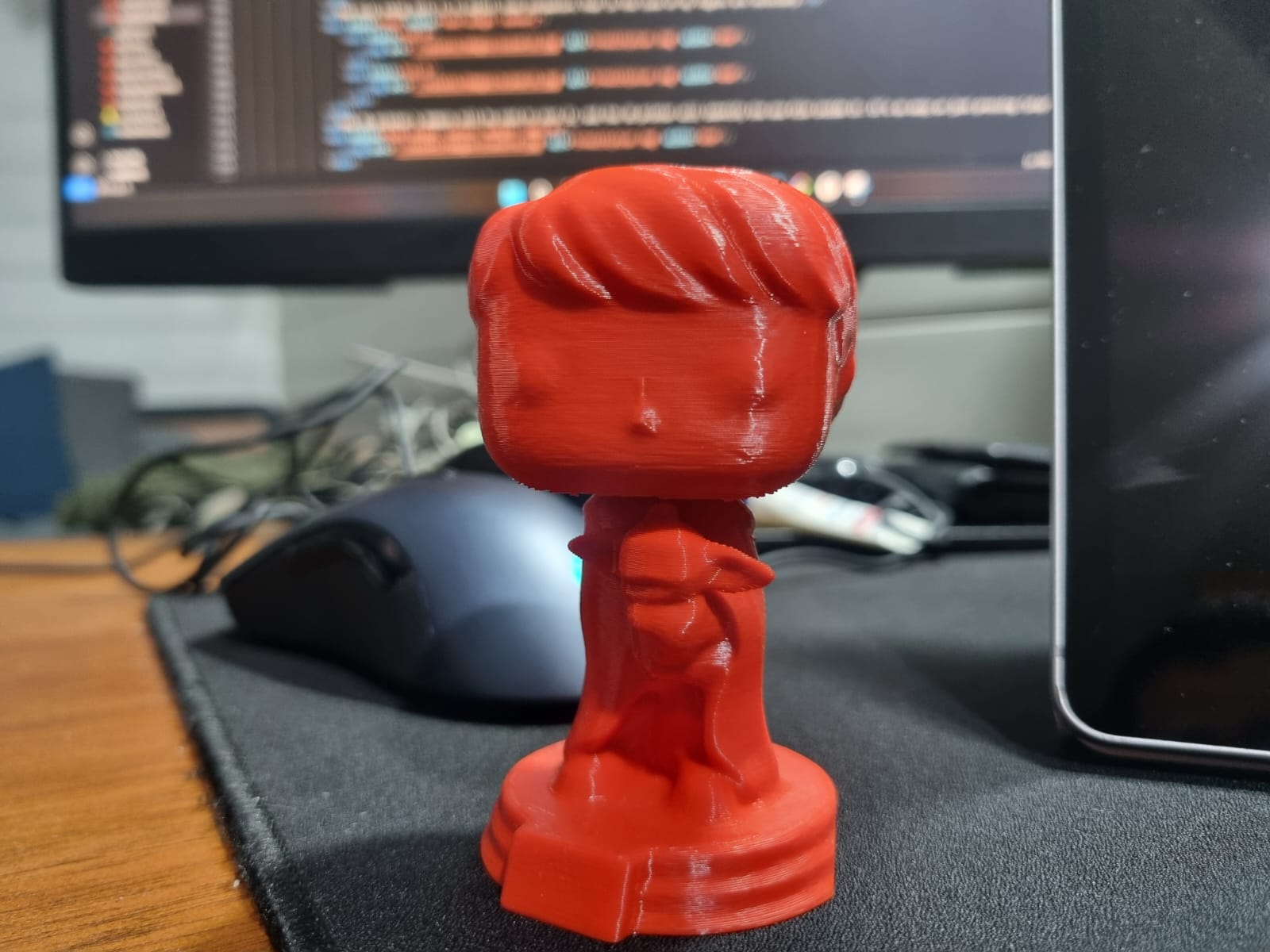
FINAL RESULT:
- 3D PRINTING -
To accomplish the second task, we need to design an object using a CAD application that cannot be manufactured using subtractive methods, and then print it using a 3D printer
I used the SolidWorks application since it's the one I'm accustomed to using. As a first step, create a "sketch" in "top view" because it's the best option since we'll be creating a spring that will go from the base upward
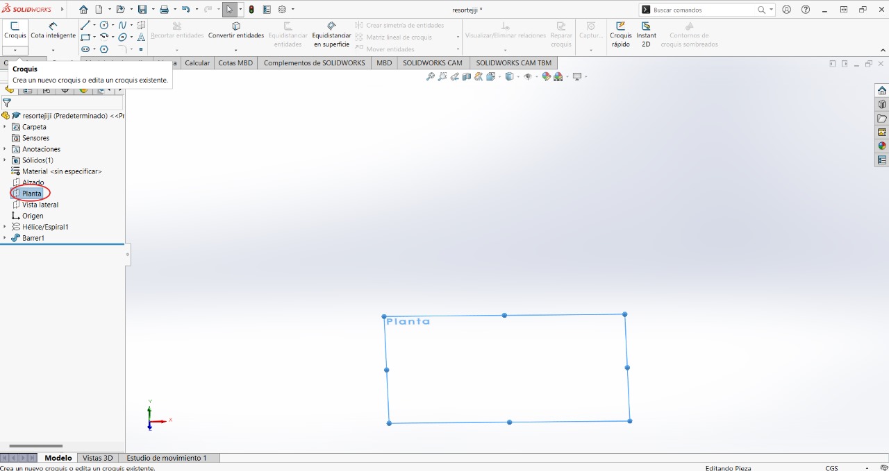
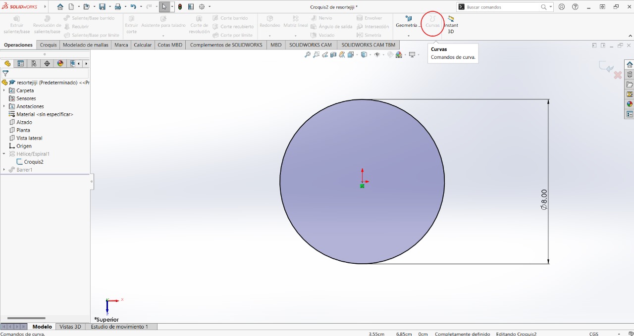
We will create a circle with the measurement shown in the image
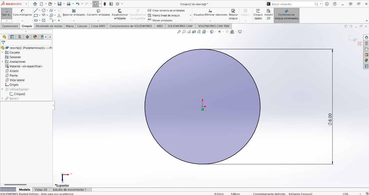
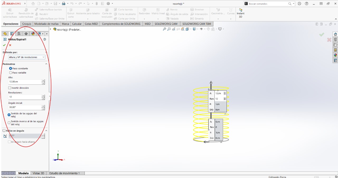
While still in the "sketch" mode, with the help of the "curves/helix, spiral" tool, we can create circles according to the diameter of the previous circle.
It will create a preview image. You can change some parameters that will appear on the left side of the screen. You can copy them so that your figure looks the same as mine
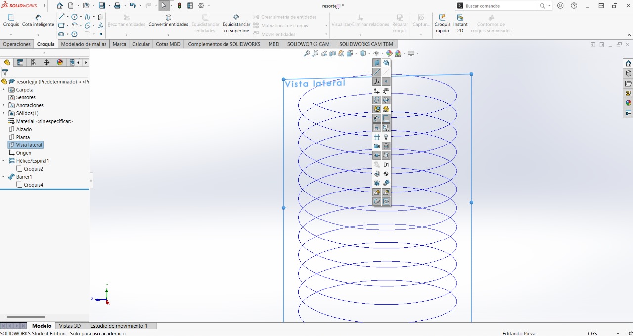
To help us know where to place the next element, which will be a circle, we activate the following option:
We will create a circle in the "side view" area
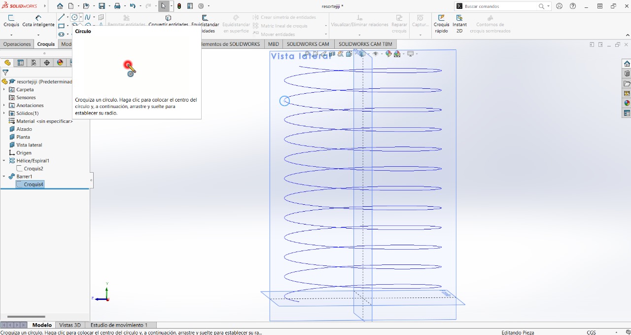
We will give it the following measurement, then we will select the middle point of the circle by also pressing "shift" and some part of the circles, and then select the "pierce" option
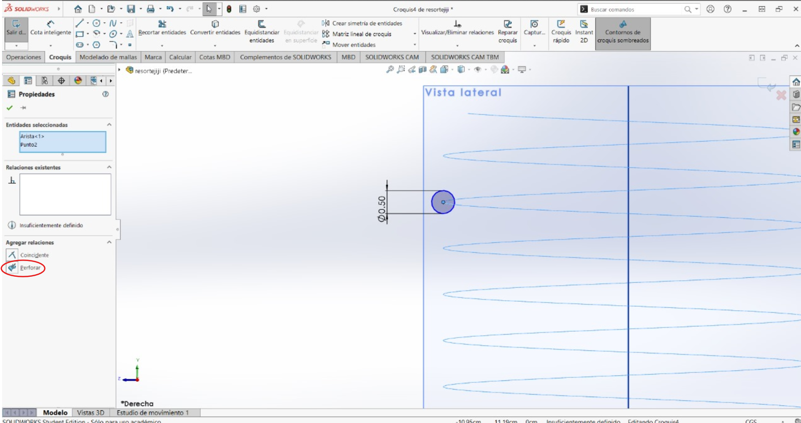
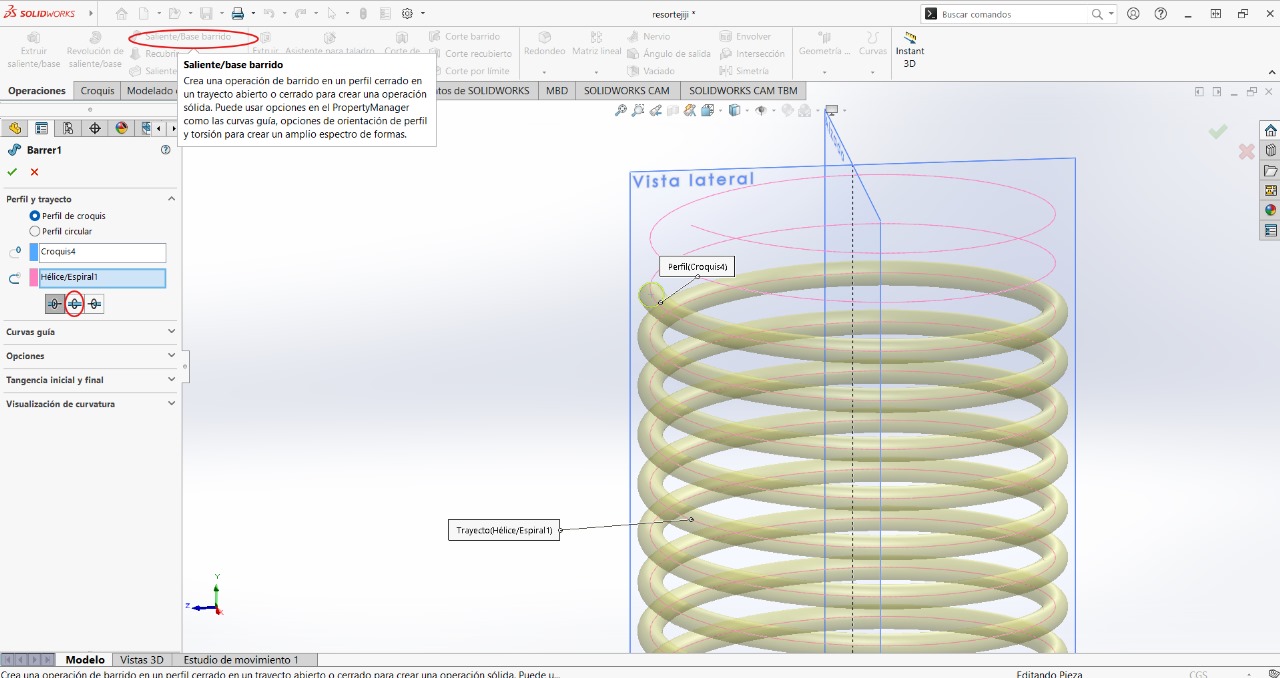
We exit the sketch to use the "Swept Boss/Base" tool. As the first option, we will select the circle and then select some part of the circles. Depending on where you placed the circle on the entire figure, I recommend selecting the second option so that it creates the entire figure according to the parameters you set
FINAL RESULT:
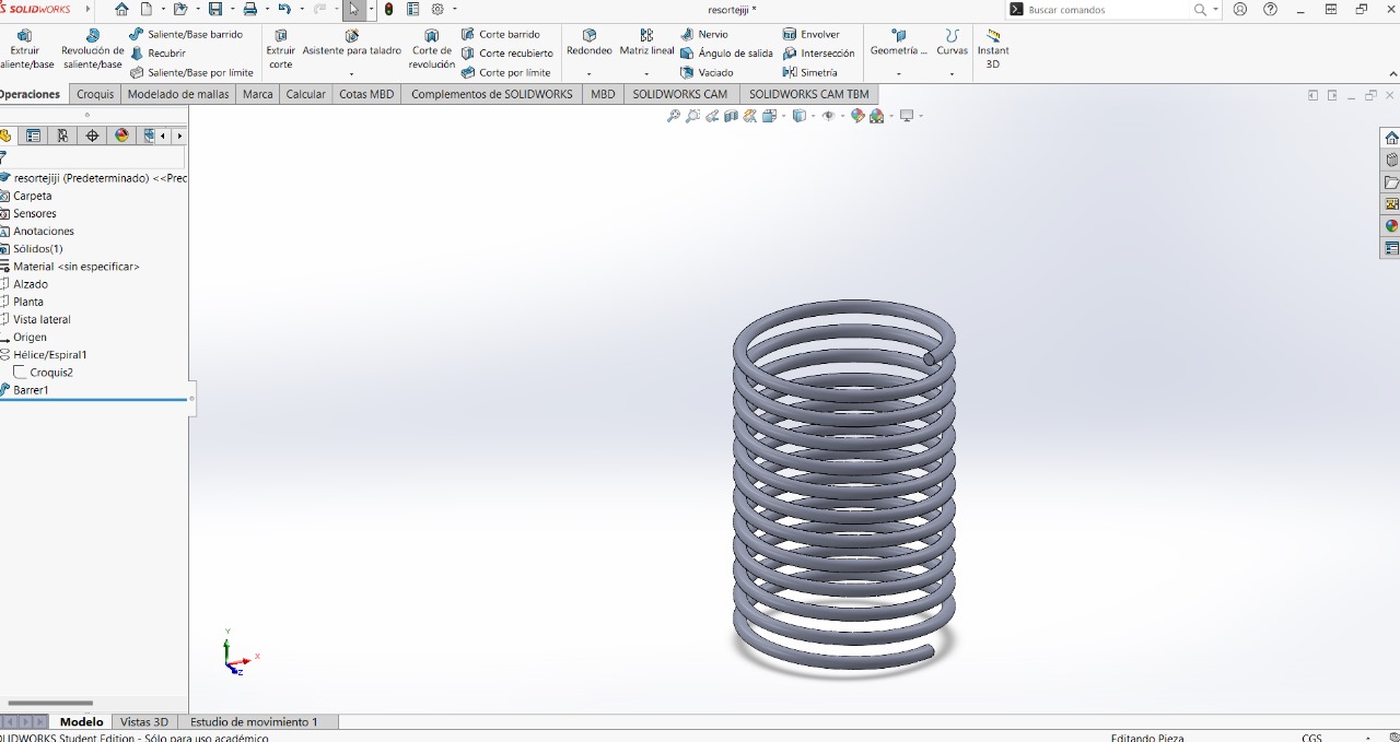
Here you can download the part: ElascticPart
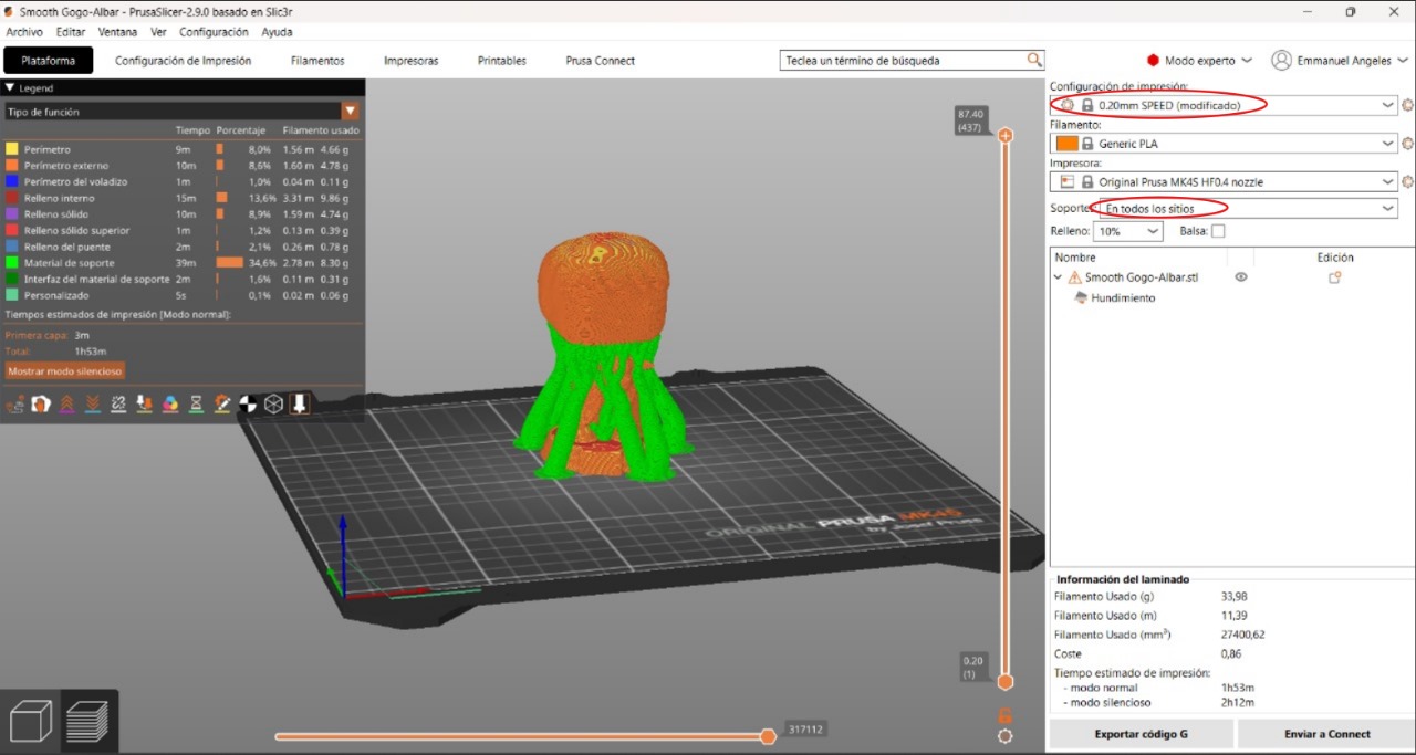
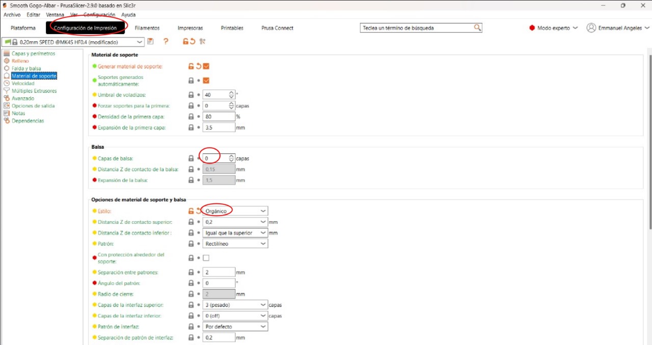
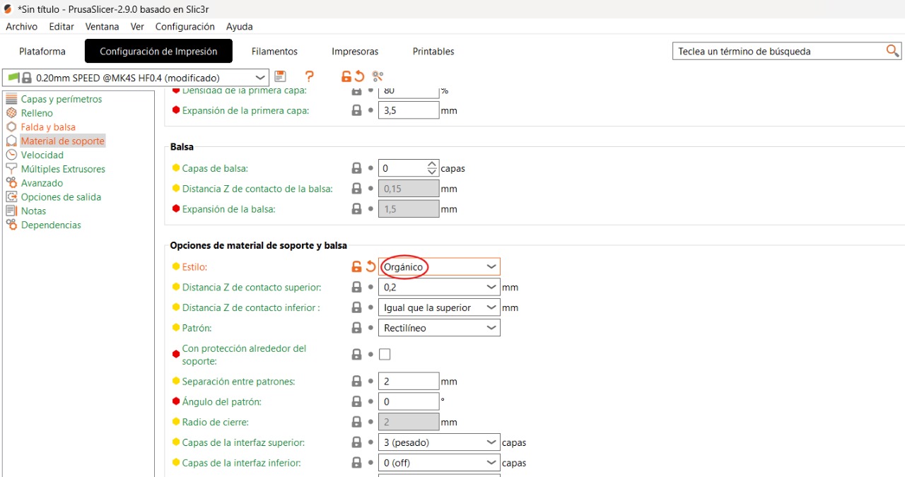
In order to 3D print, we need to use the application to configure certain settings. The first thing will be to change this parameter in Print Configuration - style - organic
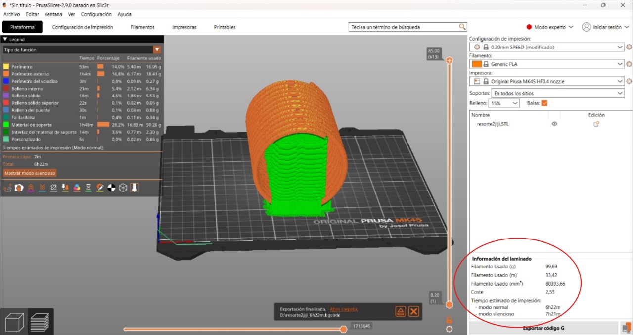
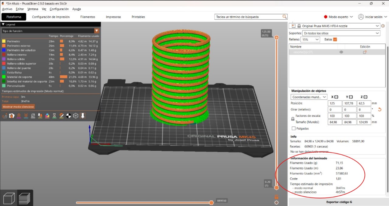
I tried both ways to print and to know which of the two methods is better in terms of material used and time taken, so you can try changing the position of the figure in the following way.You can change the position of the figure simply by changing the value in the image to 90°, click the left button on "Slice now" to see how the figure looks
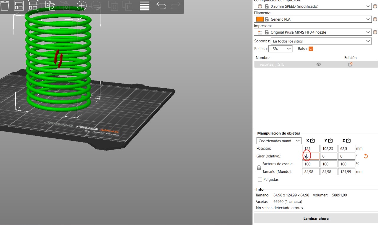
We look at the materials and time needed to select the best option
With the printer's memory, we save the file

PRINTING PROCESS:
FINAL RESULT:


