2. COMPUTER - AIDED DESIGN
CAD (Computer-Aided Design) allows the creation of technical designs in both 2D and 3D. In 2D design, you can create technical drawings, views (front, side, top), measurements, electrical diagrams, and CNC cutting patterns. For 3D design, it allows you to create three-dimensional models, part assemblies, motion simulations, realistic renderings, and stress and force analysis.
With the previous explanation, the CAD design process begins with creating sketches (measurements), then modeling (geometry, details, etc.), and finally exporting (generating files for manufacturing).
This week, we were introduced to several computer design programs in 2D and 3D. The idea this week is to familiarize ourselves with different types of software, creating the foundations for our future final project. I decided to create a part of my final project, as follows
- 3D Modelling -
Before starting, I had used CATIA before the 3D programs they taught us, but I didn't get used to using it, as I didn't like its software. Fusion 3D seemed like a good tool for 3D design, but I finally decided to use SolidWorks, as I understood better how to use its tools and I like its platform.

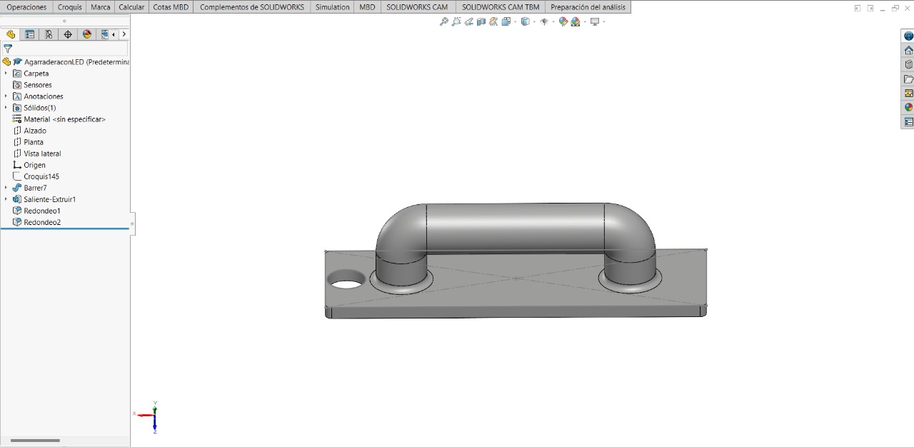
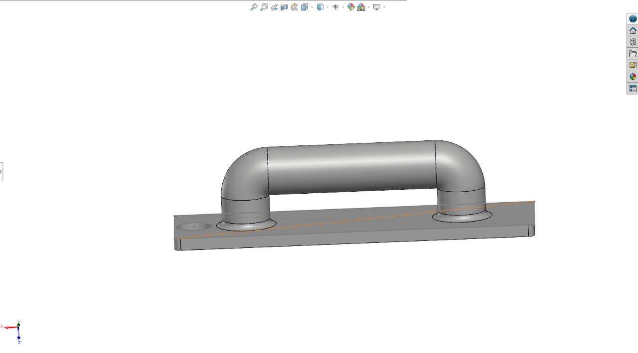
Next we will see how to build the following 3D piece in SolidWorks:
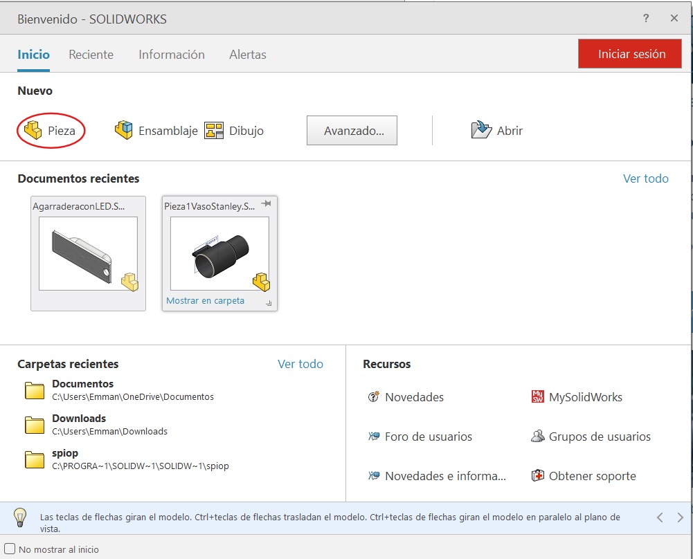
- First step - The first thing you'll see when starting SolidWorks will be this page and what you'll press is:
The next step will be to consider which plane we want to use for the 2D steps. The planes will be in the 'tree' shown in the following image.
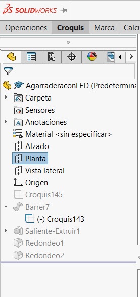
In my case, we select the 'Top' plane from the 'tree.' To be able to draw on it or on anything else, we must left-click and you will see an icon called 'sketch.' Using the drawing tools, we draw the following image

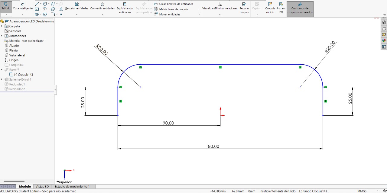
To give values to the lines and curves, you can use the 'Smart Dimension' tool within the 'Sketch' tab.
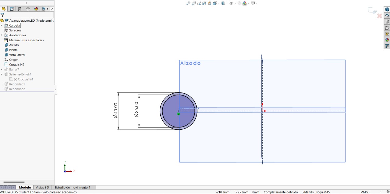
To proceed with the next step, you must select the following tool, as it will help us create a circle, but for that you must be guided by what appears thanks to the tool. We will create a circle on the circle of the line and give it a value.It is necessary to make this circle since I plan to put an LED in it that will indicate the locker's status (open = green and in this case red = closed)

It should look something like this:
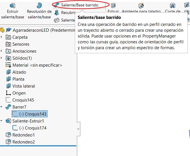
Selecting 'Sketch' from the 'Feature Tree', you must select the following tool that will help us create the 3D object.
Using one of the previously mentioned tools, to be able to see all faces, we will make a base below the cylinder that was made. For all the changes we want to make, we need to select which face we want to make the change on. In this case, we need to make a square with the following values:
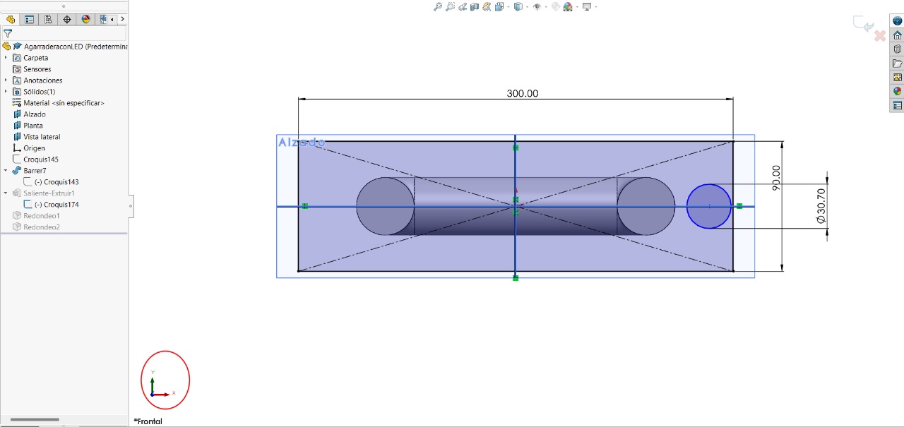
When the 'sketch' is created, you must select the 'Extrude Boss/Base' tool to create a 3D base.
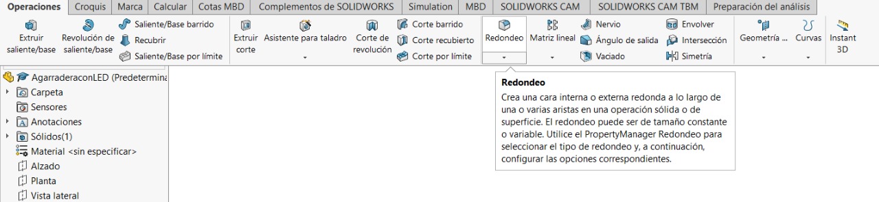
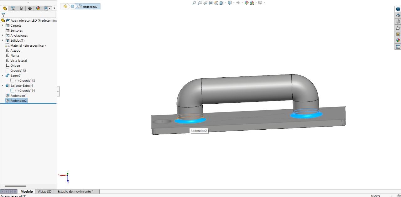
As a final step, we should give some design to the piece, using the tool:

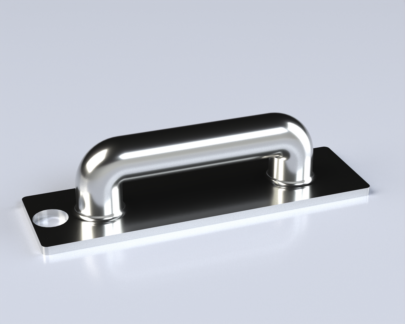
Render part:
3D Model:
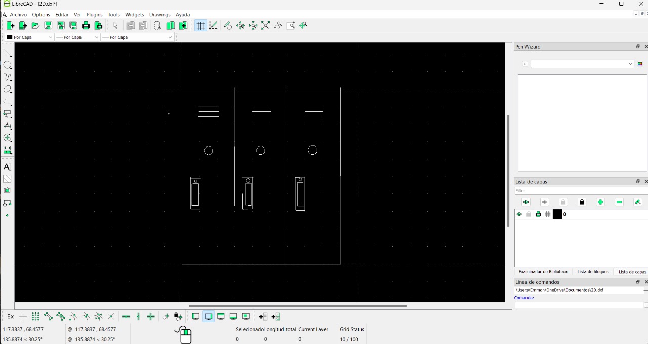
- 2D MODELLING -
For 2D, I wanted to design the model of what the locker would look like, without including perhaps certain parts like solar panels for electricity, number panels and others.
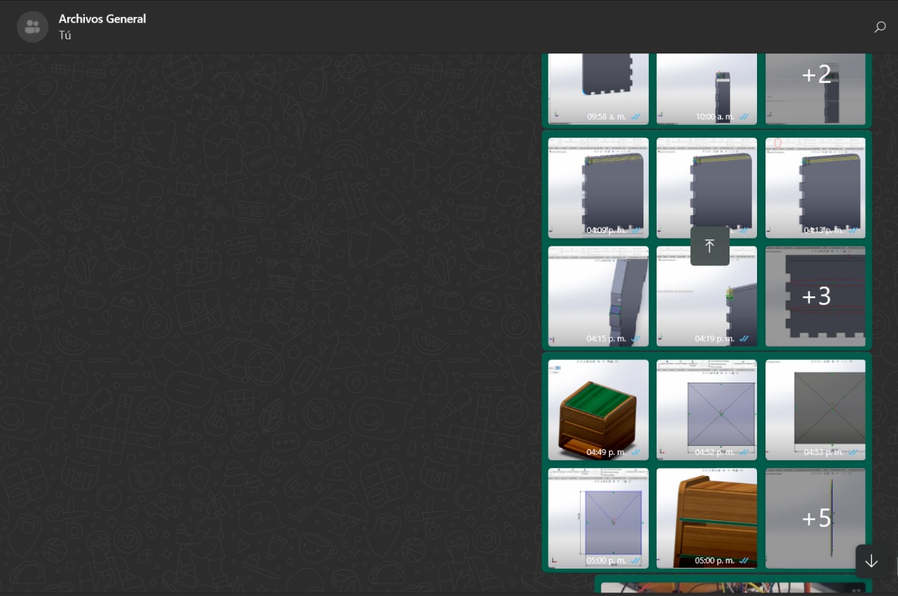
- IMAGE AND VIDEO COMPRESSION -
For image and video compression I´m using Whats´App. This group is mine, where I am alone, and previously I had it to send myself PDFs or reminders about the University. Currently I mostly send things related to the documentation of the weeks