11. Networking and Communications
This week, I worked on designing, building, and connecting wired or wireless node(s) with network or bus addresses and local input and/or output devices.
Group Task:
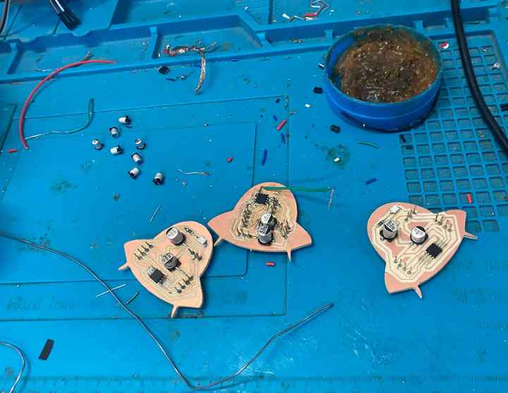
Group task- First, I explored different PCB designs.
- I have a XIAO, but it runs at 3.3V, so it wasn’t the best option.
- So, I decided to design another PCB like the one I made last week.
which pcb am I going to use?🛸🛸
Protocols
Wired Communication Protocols
| Characteristic | I2C | SPI | UART |
|---|---|---|---|
| Required Cables | 2 (SDA, SCL) | 4 (MISO, MOSI, SCK, SS) | 2 (TX, RX) |
| Speed | Low | High | Medium |
| Devices | Multiple (up to 128) | Few (1 master, 1 slave) | 1 to 1 |
| Connection | Simple | More cables, more complex | Simple and direct |
| Common Use | Multiple sensors/devices | High-speed transfer | Communication between 2 devices |
Wireless Communication Protocols
| Protocol | Range | Transmission Speed | Power Consumption | Common Use |
|---|---|---|---|---|
| Wi-Fi | Medium (up to 100 m) | High (up to 1 Gbps) | High | Internet connections in homes and offices |
| Bluetooth | Short (up to 100 m) | Moderate (up to 3 Mbps) | Low | Connection between personal devices (headphones, keyboards) |
| ZigBee | Short (10-100 m) | Low (up to 250 kbps) | Very low | Home automation and sensor networks |
| LoRa | Long (up to 15 km in rural areas) | Very low (up to 27 kbps) | Low | Long-range IoT applications |
| LTE-M | Medium (similar to 4G) | Moderate (up to 1 Mbps) | Moderate | IoT devices requiring mobility |
| NB-IoT | Medium (up to 10 km) | Low (up to 250 kbps) | Low | Low-power, wide-area IoT devices |
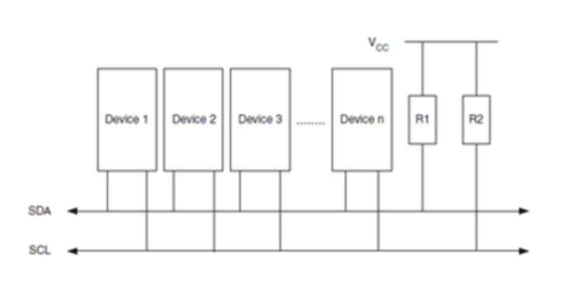
I2C
In this task i decided to comunicate my microcontrollers with I2C comunication.
PCB Creation and Pinout Design
To create another PCB, I followed the same steps as last week since I made the same PCB. I swapped the ATtiny in the first PCB, and this time it was programmed successfully.
-
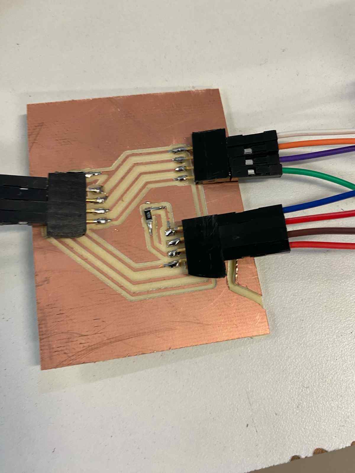
However, I became aware that I didn’t have enough pinouts, so I decided to create a PCB that would show these pinouts.
-
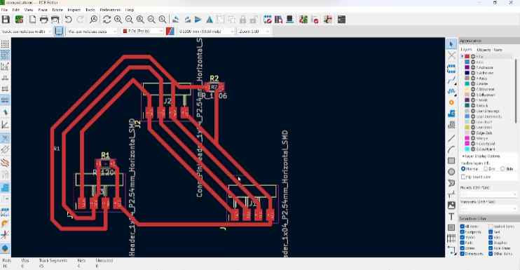
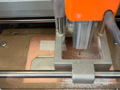
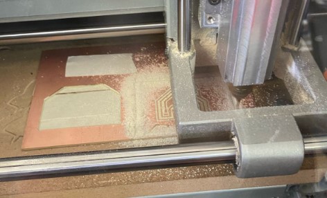
I designed this part in KiCad.
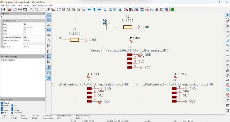
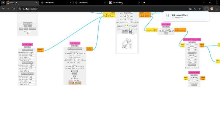
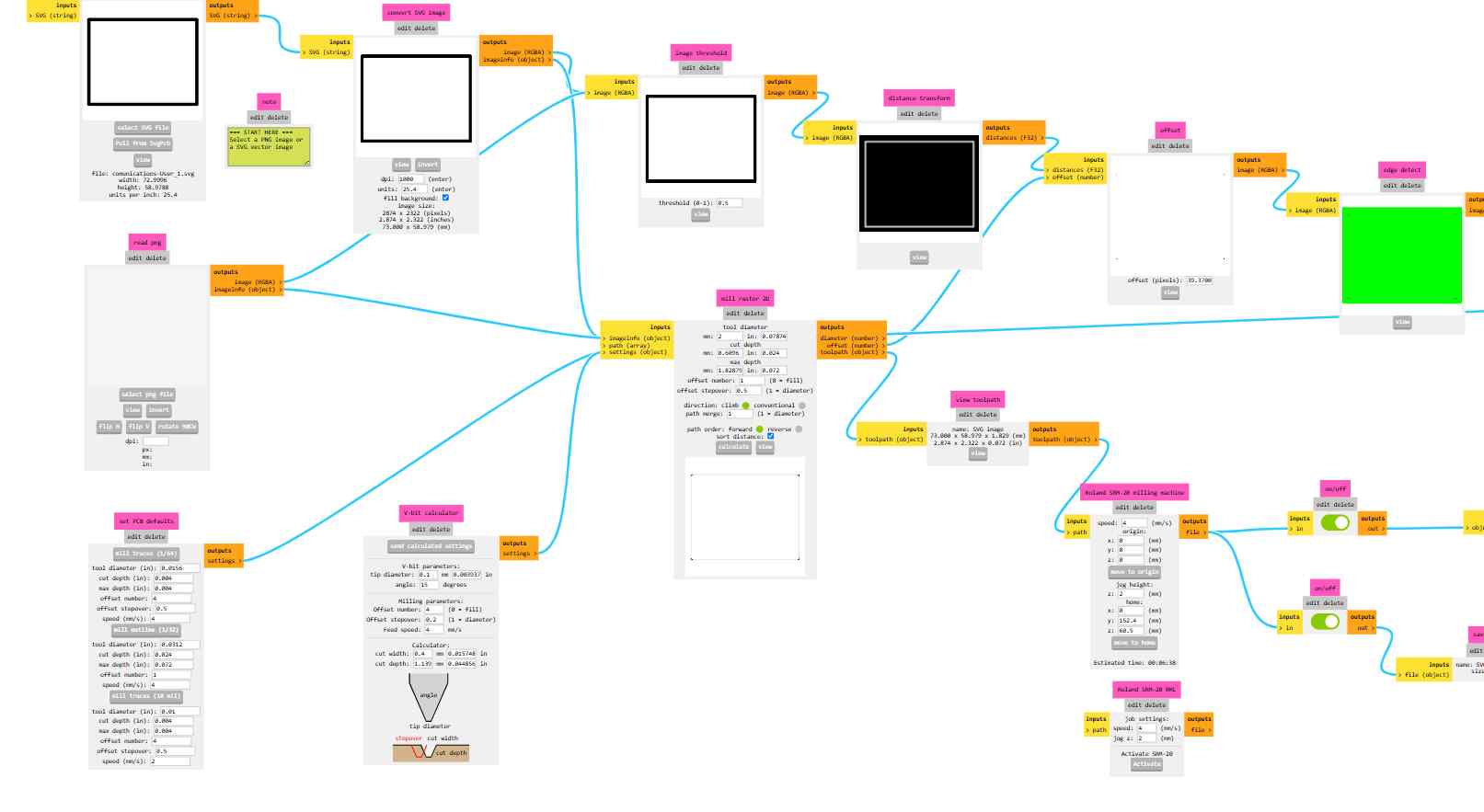
Then I engraved and cut it at Monofab.
-
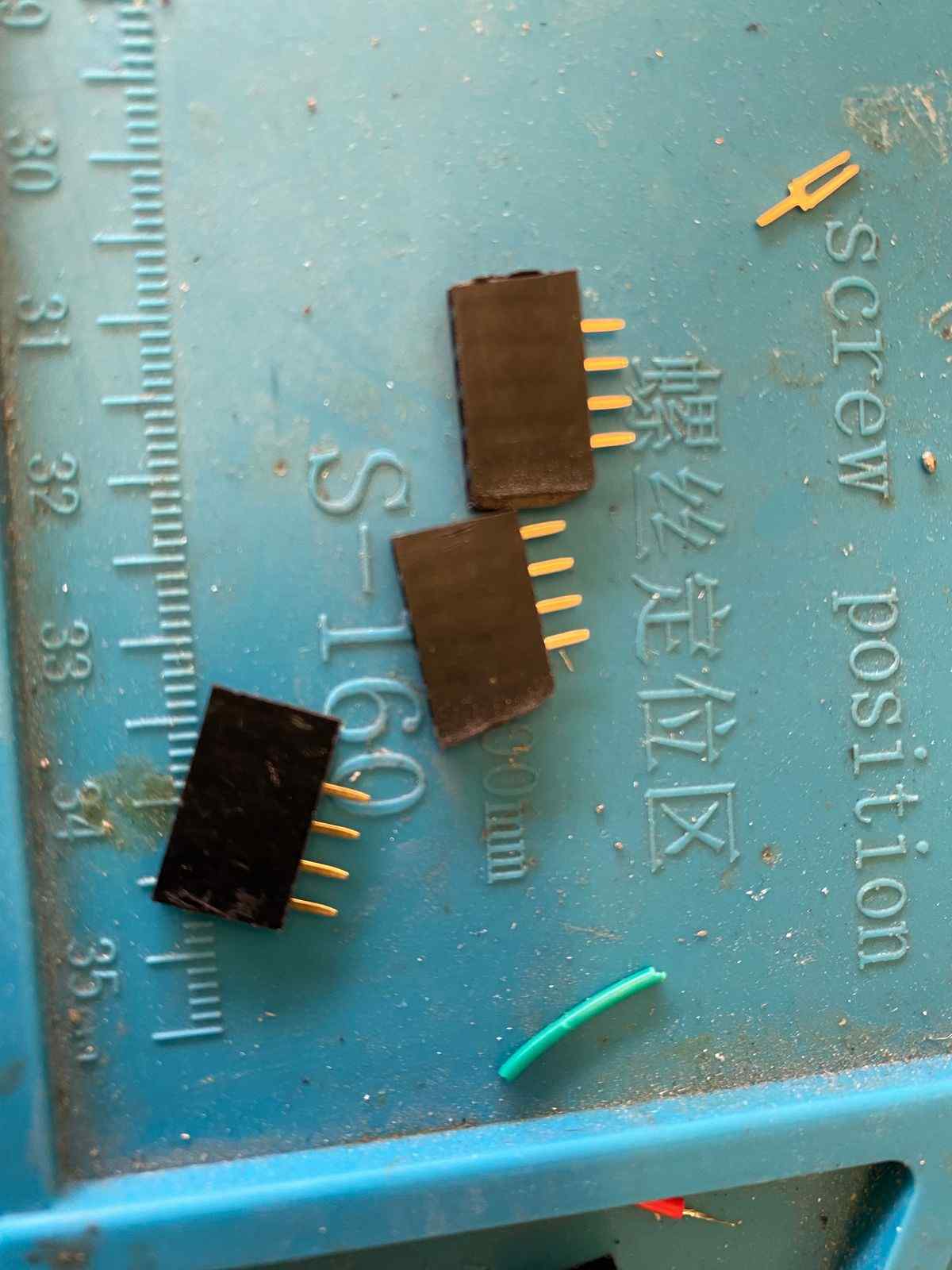
Finally, I soldered the resistors first and then the pins.
Comunication between only two aTTinys
In this communication, I only pressed the button on the main, and the secondary responded with a blink.
To start with the code, I began by installing the necessary libraries:
- Secondary library:
#include <TinyWireS.h> - Main library:
#include <TinyWireM.h>
Secondary code (PCB with the Led)
#include

#define LED_PIN PB4
#define I2C_SLAVE_ADDR 0x04

void receiveEvent(uint8_t howMany) {
  while (TinyWireS.available()) {
    char c = TinyWireS.read();
    if (c == 'A') {
      digitalWrite(LED_PIN, HIGH);
      delay(500);
      digitalWrite(LED_PIN, LOW);
    }
  }
}

void setup() {
  pinMode(LED_PIN, OUTPUT);
  TinyWireS.begin(I2C_SLAVE_ADDR);
  TinyWireS.onReceive(receiveEvent);
}

void loop() {
  TinyWireS_stop_check();
Function: receiveEvent(uint8_t howMany)
- Automatically triggered when the I2C master sends data.
- Checks if data is available using
TinyWireS.available(). - Reads each byte with
TinyWireS.read(). - If the received byte is the character
'A':- Turns the LED on.
- Waits 500 milliseconds (
delay(500)). - Turns the LED off.
Function: setup()
pinMode(LED_PIN, OUTPUT);
Sets the LED pin as an output.TinyWireS.begin(I2C_SLAVE_ADDR);
Initializes I2C in slave mode with address0x04.TinyWireS.onReceive(receiveEvent);
RegistersreceiveEventas the handler for incoming I2C data.
Function: loop()
TinyWireS_stop_check();
Required in theloop()to allowTinyWireSto properly detect I2C stop conditions.
Main Code(PCB with the button)
#include   // Include the Wire library for I2C communication

#define BUTTON_PIN PB3      // The button is connected to pin PB3 (physical pin 2)
#define SLAVE_ADDR 0x04     // I2C address of the slave device

void setup() {
  pinMode(BUTTON_PIN, INPUT_PULLUP);  // Set the button pin as input with internal pull-up resistor
  Wire.begin();  // Initialize I2C as master
}

void loop() {
  // Check if the button is pressed (LOW because of pull-up)
  if (digitalRead(BUTTON_PIN) == LOW) {
    Wire.beginTransmission(SLAVE_ADDR);  // Start communication with the slave
    Wire.write('A');  // Send the character 'A' as a command
    Wire.endTransmission();  // End transmission and send the data
    delay(300);  // Wait to avoid bouncing or multiple signals too quickly
  }
}
My PCBs working🛸
Comunication between three ATTinys
Secondary Code
I indicated the pins and their functions and I set the address for each secondary device. For the first, I used 0x10, and for the second, 0x20.
Then, I declared a volatile 8-bit unsigned integer named command, initialized to 0. This variable's value might change unexpectedly, so it is important to always read its current value directly from memory.
After that, I had to implement the receiveEvent function which activates itself when a data arrives. This function reads the number it receives and, if it is 1, it turns on an LED; if it is 0, it turns it off. For this reason, the ATtiny listens to what the other chip sends it.
Code(Secondary1)
#include

#define I2C_ADDRESS 0x10
#define LED_PIN 4

volatile uint8_t command = 0;  // Variable to store the received command

// Function to handle incoming data from the controller
void receiveEvent(uint8_t howMany) {
  if (howMany < 1) return;             // Exit if no data is received
  command = TinyWireS.read();          // Read the incoming byte
  digitalWrite(LED_PIN, command ? HIGH : LOW); // Set LED state based on command
}

void setup() {
  pinMode(LED_PIN, OUTPUT);            // Set the LED pin as an output
  digitalWrite(LED_PIN, LOW);          // Ensure the LED is off initially
  TinyWireS.begin(I2C_ADDRESS);        // Initialize I²C communication with the specified address
  TinyWireS.onReceive(receiveEvent);   // Register the receive event handler
}

void loop() {
  TinyWireS_stop_check();              // Continuously check for stop condition from the controller
}
Code(Secondary2)
#include

#define I2C_ADDRESS 0x20
#define LED_PIN 4

volatile uint8_t command = 0;  // Variable to store the received command

// Function to handle incoming data from the controller
void receiveEvent(uint8_t howMany) {
if (howMany < 1) return;             // Exit if no data is received
command = TinyWireS.read();          // Read the incoming byte
digitalWrite(LED_PIN, command ? HIGH : LOW); // Set LED state based on command
}

void setup() {
pinMode(LED_PIN, OUTPUT);            // Set the LED pin as an output
digitalWrite(LED_PIN, LOW);          // Ensure the LED is off initially
TinyWireS.begin(I2C_ADDRESS);        // Initialize I²C communication with the specified address
TinyWireS.onReceive(receiveEvent);   // Register the receive event handler
}

void loop() {
TinyWireS_stop_check();              // Continuously check for stop condition from the controller
}
Main
For this code, I based it on the idea of making the system automatic.
This is the website I referred to for the code:
Example AssignmentBase code(Main)
#include
#define device (1)
#define slave (2)
void setup() {
  TinyWireM.begin();
}
void loop()
{
  TinyWireM.beginTransmission(device);
  TinyWireM.send(1);
  TinyWireM.endTransmission();
  delay(1000);
  TinyWireM.beginTransmission(device);
  TinyWireM.send(2);
  TinyWireM.endTransmission();
  delay(1000);
  TinyWireM.beginTransmission(slave);
  TinyWireM.send(1);
  TinyWireM.endTransmission();
  delay(1000);
  TinyWireM.beginTransmission(slave);
  TinyWireM.send(2);
  TinyWireM.endTransmission();
  delay(1000);

}
Code(Main)
#include   // Library for I²C master functionality on ATtiny

#define SLAVE1_ADDR 0x10  // I²C address of the first slave device
#define SLAVE2_ADDR 0x20  // I²C address of the second slave device

void setup() {
  TinyWireM.begin();  // Initialize I²C communication as master
}

void loop() {
  // Turn on LED of slave 1
  TinyWireM.beginTransmission(SLAVE1_ADDR);  // Start communication with slave 1
  TinyWireM.write(1);                        // Send command to turn on LED
  TinyWireM.endTransmission();               // End communication

  // Turn off LED of slave 2
  TinyWireM.beginTransmission(SLAVE2_ADDR);  // Start communication with slave 2
  TinyWireM.write(0);                        // Send command to turn off LED
  TinyWireM.endTransmission();               // End communication

  delay(1000);  // Wait for 1 second

  // Turn off LED of slave 1
  TinyWireM.beginTransmission(SLAVE1_ADDR);  // Start communication with slave 1
  TinyWireM.write(0);                        // Send command to turn off LED
  TinyWireM.endTransmission();               // End communication

  // Turn on LED of slave 2
  TinyWireM.beginTransmission(SLAVE2_ADDR);  // Start communication with slave 2
  TinyWireM.write(1);                        // Send command to turn on LED
  TinyWireM.endTransmission();               // End communication

  delay(1000);  // Wait for 1 second
}
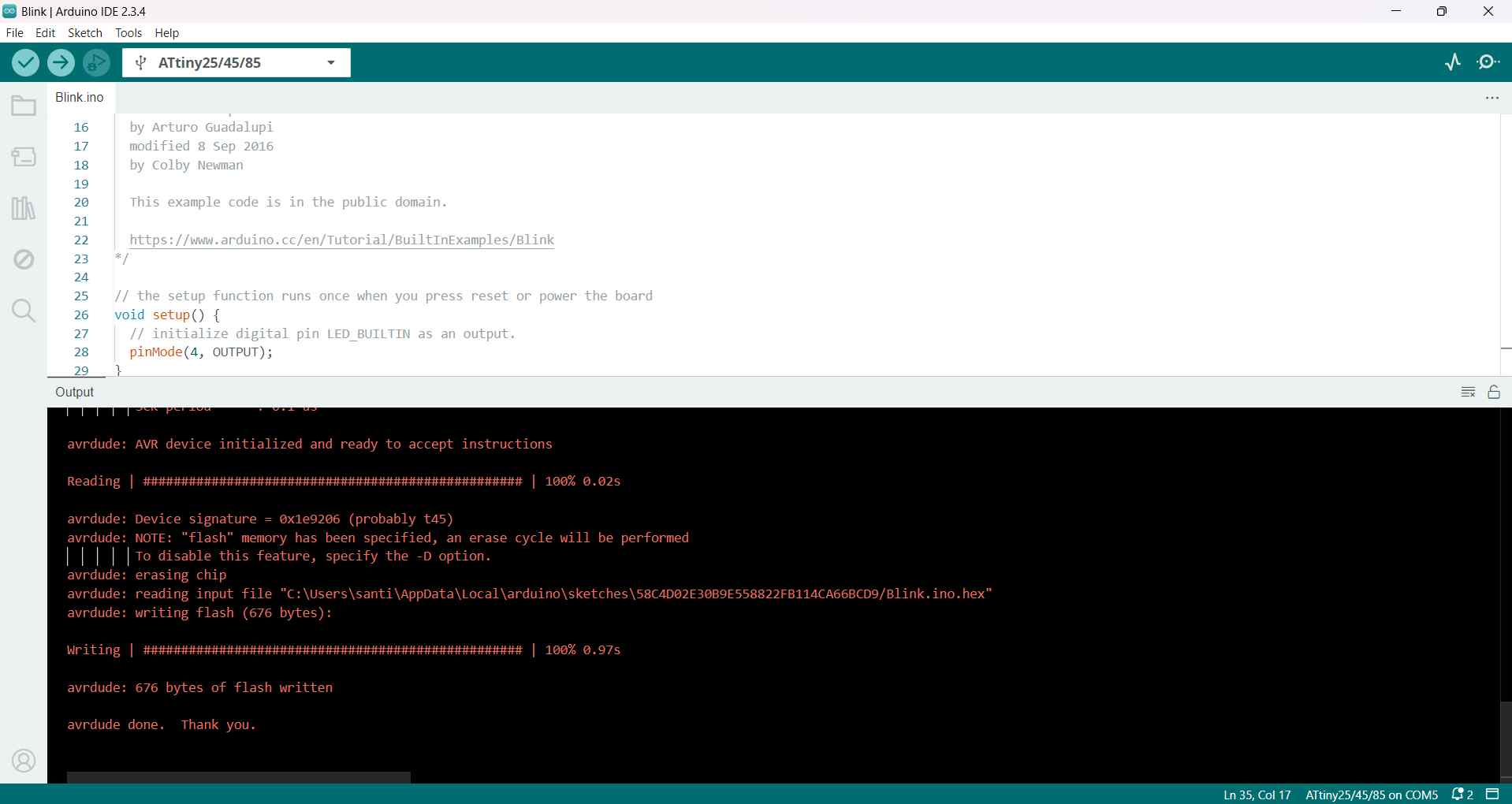
Charging the Code
I programmed my Attinys with an Arduino
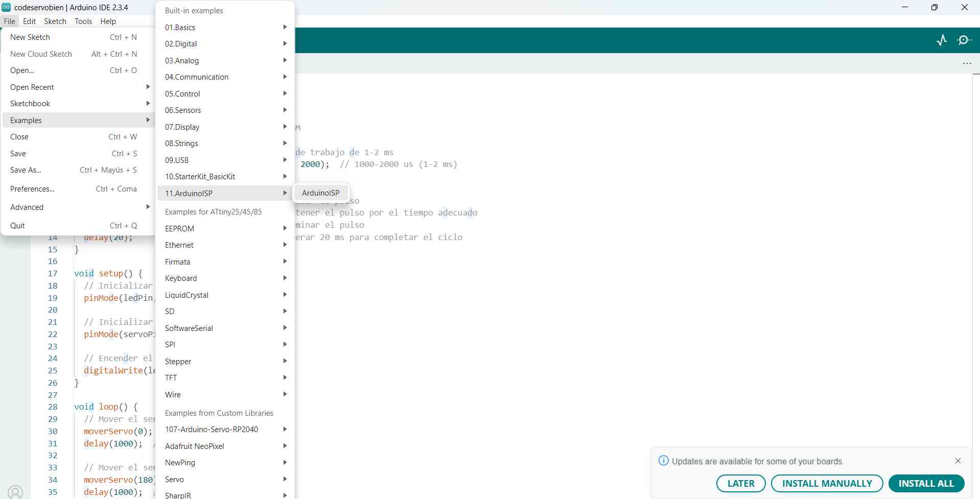
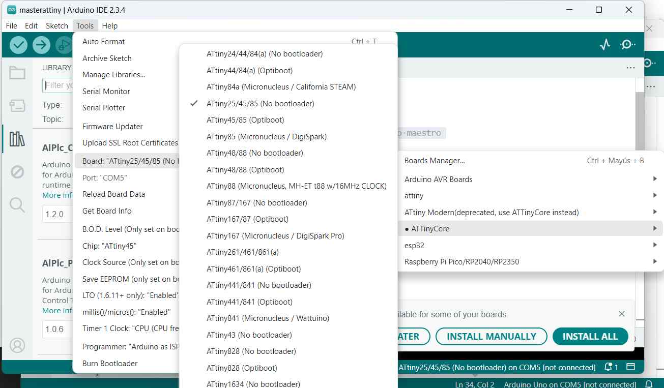
How I Programmed an ATtiny45?
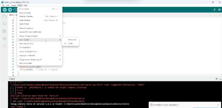
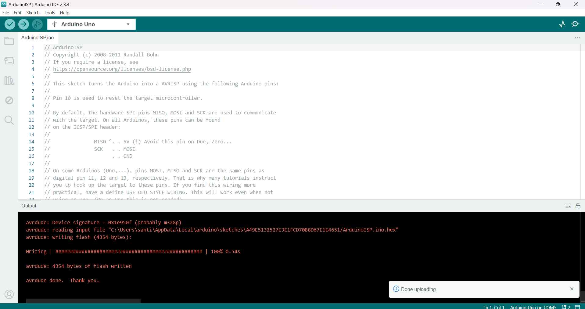
- I uploaded the ArduinoISP code with these configurations.
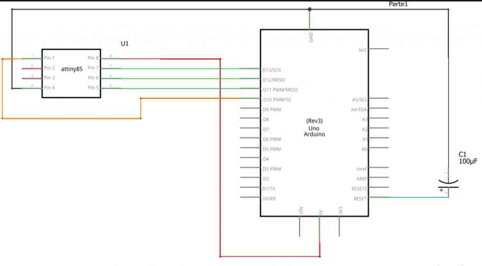
- Then, I connected the ATtiny85 to the Arduino Uno using the following diagram.
- Next, I added the following URL in the Preferences section and installed it:
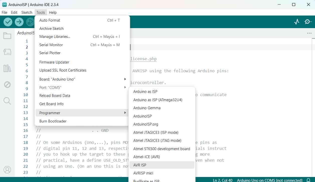
https://raw.githubusercontent.com/damellis/attiny/ide-1.6.x-boards-manager/package_damellis_attiny_index.json - Then, I applied the following configurations.
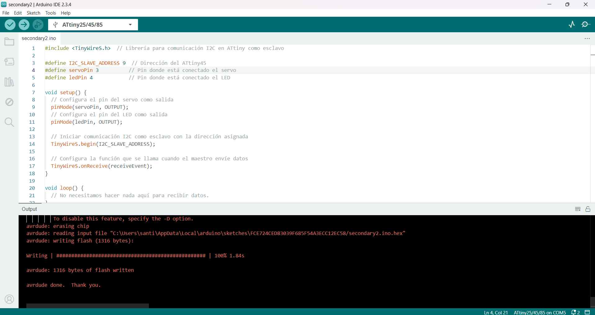
- Finally, I burned the bootloader and uploaded my code. After that, I tested my code on my PCB.
- Only 1 led blinked, and I didn’t understand why.
- I checked the PCB with a multimeter but couldn’t find the issue.
- So, I changed something in my program, burned the bootloader, and re-uploaded the code.
- Finally, it worked as expected.
Some Complications
My PCBs working🛸
Files
Conclusion🛸🛸
This was the most difficult week for me because I had to understand how the microcontrollers would communicate. However, I feel more comfortable using ATtiny's and their limitations .