10.Output Devices
This week, I have to add an output device to my microcontroller board. To do this, I tried using Neopixels and servos. What I did was to use a potentiometer to change the color of the Neopixel. If the color was red, the servo moved; otherwise, the servo went back to 54 degrees. Also, I decided to make another PCB with an Attiny45 to move a servo.🛸🛸
Group Task:
Group taskWhat is an output device?
Output devices are electronic components that receive signals from a system and transform them into a form that is perceptible to the user or that performs a specific action. These devices convert the information processed by the system into a physical or visual response. Some common examples of output devices include displays, speakers, motors, LED lights, printers, and servos.
For this practice, I used the following components: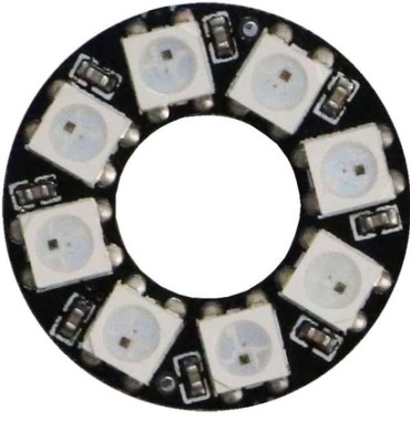
The WS2812 ring
The WS2812 ring is a powerful high-intensity RGB LED, all of which are controlled through a single data line. Additionally, each LED can be controlled independently.
Specifications:
- Voltage: 4-7V
- LED Model: WS2812B
- Color: RGB
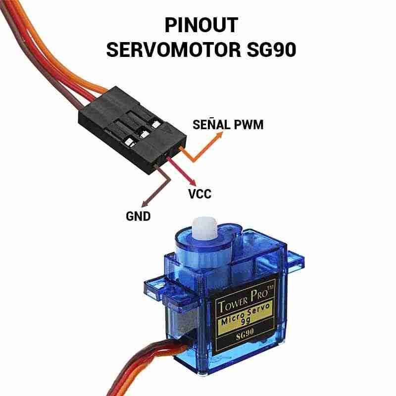
SG-90 Servo Motor
The SG90 RC 9g Servomotor is a motor that allows precise control of the angular position from 0° to 180° by means of a PWM signal.
Specifications:
- Voltage: 3V-7.2V
- Torque: 2.5kg/cm
- Operating speed: 0.1s/60°
- Gear type: Plastic
- Rotation: 0°-180°
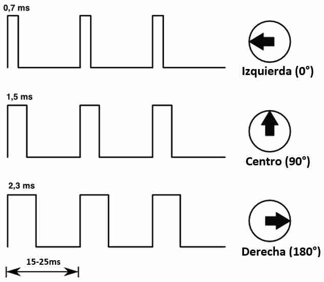
What is PWM and how does it control the servo position?
The signal sent to a servo is a pulse-width modulation (PWM) signal, where the pulse's high time determines the servo's position. The signal values range from 0.5 to 1 milliseconds for the 0° position and 2 to 2.4 milliseconds for the 180° position. The total signal period, meaning the full signal cycle, should be around 20 milliseconds. By varying the pulse duration within this range, the servo adjusts its angle or position according to the pulse duration it receives.
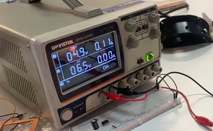
Power consumption
Neopixel Power Consumption
The power consumption of a Neopixel is calculated using the formula:
P = V × I
In this case, the Neopixel operates at 5V with a current of 0.11A.
Therefore, the power consumed by the Neopixel is:
P = 5V × 0.11A = 0.55W
Servo Power Consuption
It varies between 0.02A and 0.34A (minimum and maximum current)
I calculated these values:- Minimum power: P = 5V × 0.02A = 0.1W
- Maximum power: P = 5V × 0.34A = 1.7W
programming
Now it's time to program 🛸🛸.
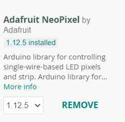
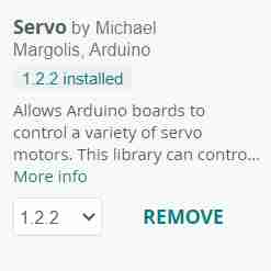
To start my code, I have to import the Servo and Neopixel libraries.
Code
#include   // Include the library to control the servo
#include   // Include the library to control the Neopixel LEDs

// Define pin connections
#define SERVO_PIN D9  // Pin where the servo is connected
#define POT_PIN D2  // Pin where the potentiometer is connected
#define NEOPIXEL_PIN D10  // Pin where the Neopixel strip is connected

// Create servo object
Servo myServo;

// Create Neopixel strip object with 8 LEDs
Adafruit_NeoPixel strip = Adafruit_NeoPixel(8, NEOPIXEL_PIN, NEO_GRB + NEO_KHZ800);

void setup() {
  myServo.attach(SERVO_PIN);  // Attach the servo to its pin
  strip.begin();  // Initialize the Neopixel strip
  Serial.begin(115200);  // Start serial communication at 115200 baud rate

  // Set the initial position of the servo to 0 degrees
  myServo.write(0);

  // Set all Neopixel LEDs to red at startup
  for (int i = 0; i < strip.numPixels(); i++) {
    strip.setPixelColor(i, strip.Color(255, 0, 0));  // Set each LED to pure red
  }
  strip.show();  // Update the Neopixel strip to apply the color
}

void loop() {
  int potValue = analogRead(POT_PIN);  // Read the potentiometer value (0 to 4095)
  Serial.print("Potentiometer: "); Serial.println(potValue);  // Print the value

  // Map potentiometer value to servo angle (45° to 180°)
  int angle = map(potValue, 0, 4095, 45, 180);

  // Ensure the angle stays within the range of 45° to 180°
  angle = constrain(angle, 45, 180);

  // Map the angle to LED colors (green increases as angle increases)
  int greenValue = map(angle, 45, 180, 0, 255);
  int redValue = 255 - greenValue;  // Red decreases as green increases

  // Update all Neopixel LEDs with the new color
  for (int i = 0; i < strip.numPixels(); i++) {
    strip.setPixelColor(i, strip.Color(redValue, greenValue, 0));
  }
  strip.show();  // Apply the new colors to the LEDs

  // If the red value is high, move the servo to the corresponding angle
  if (redValue >= 200) {
    myServo.write(angle);
  } else {
    myServo.write(45);  // If red is low, set servo to minimum 45°
  }

  delay(50);  // Small delay for stability
}
The outputs working🛸
Doing another PCB🛸
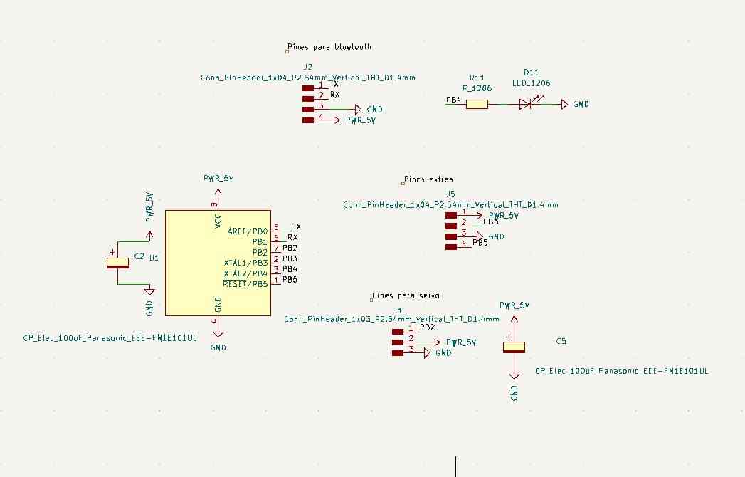
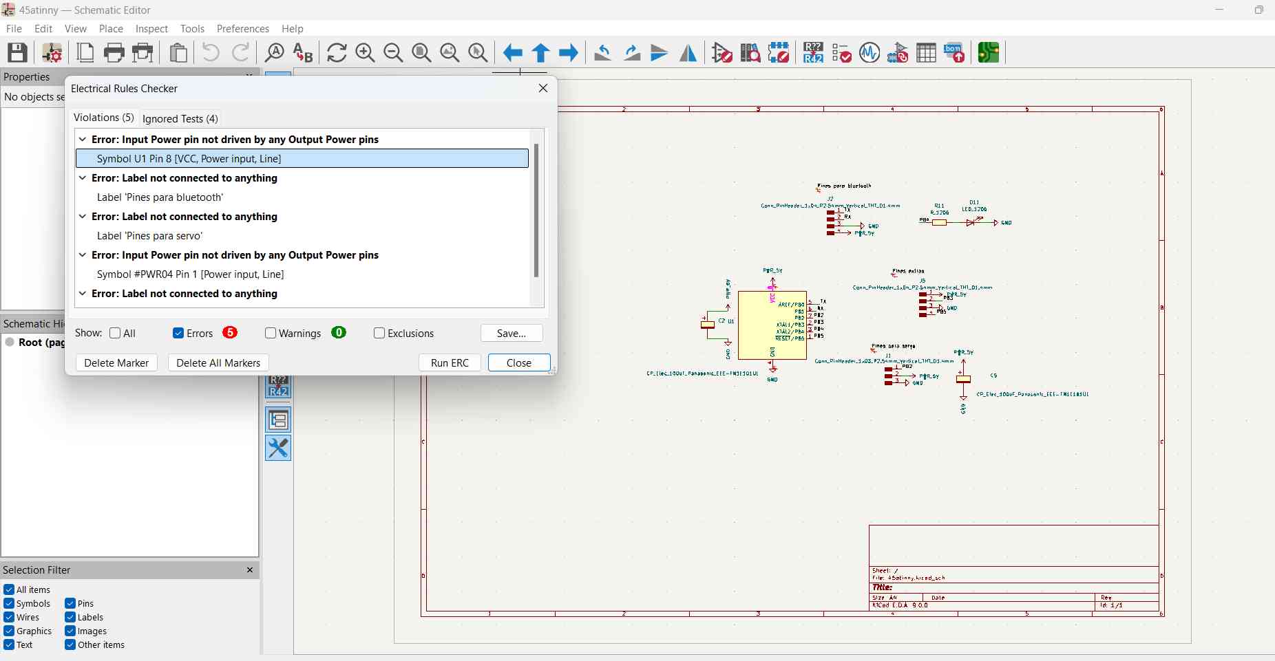
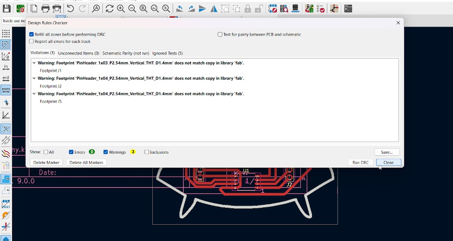
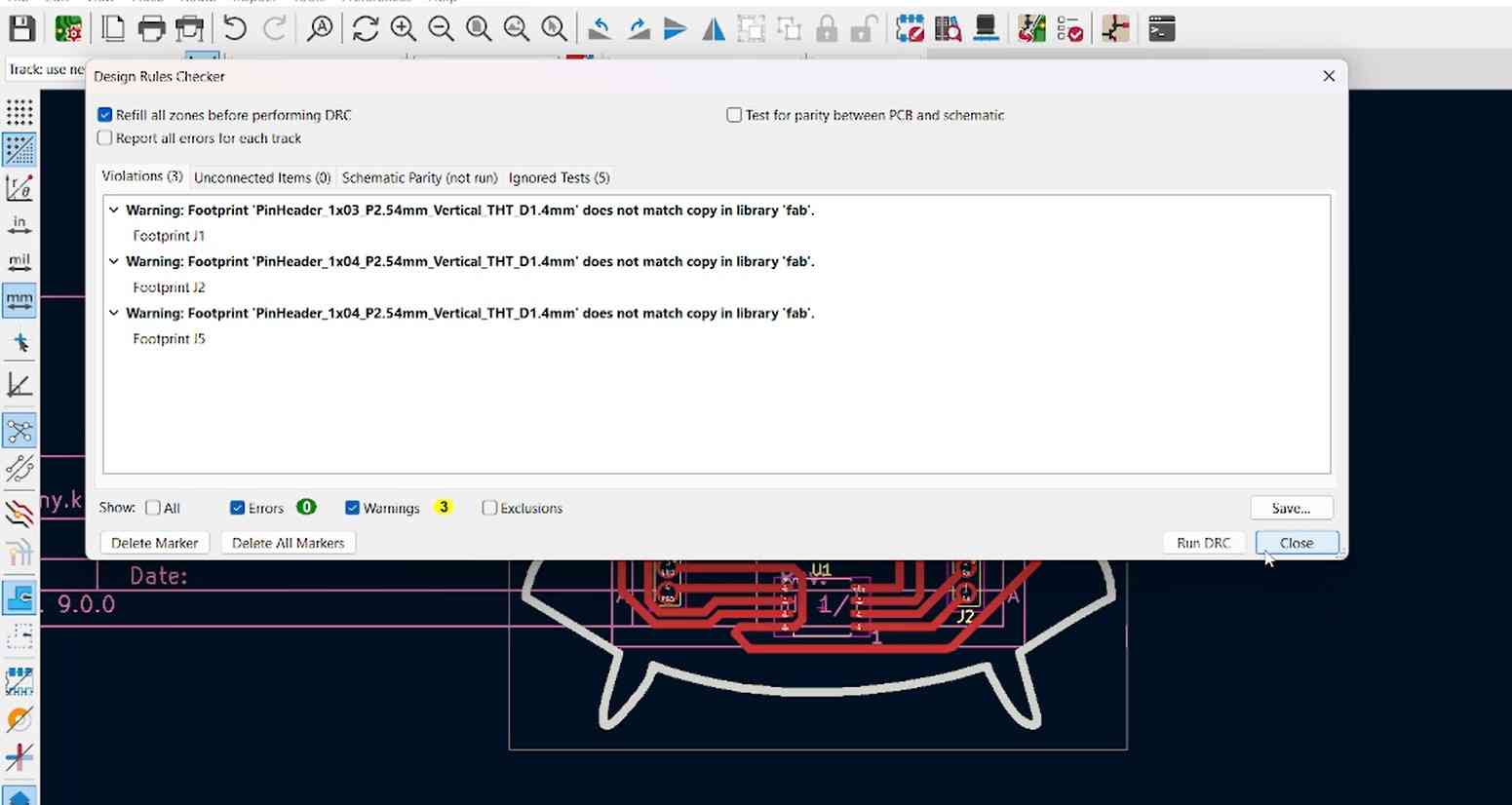
First, i designed my pcb in KiCad

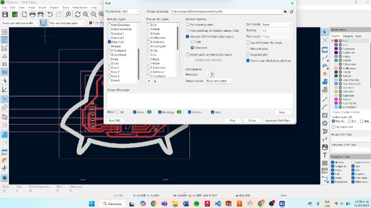
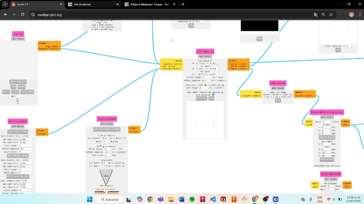
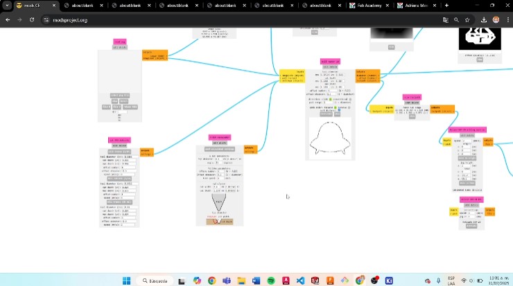
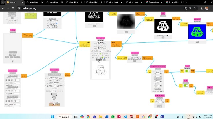
Using mods to create my file .rml
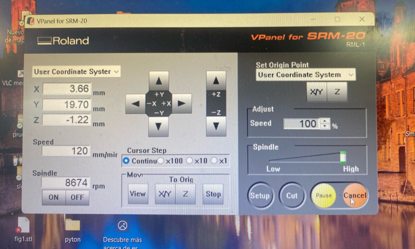
- First went to mods, selected the “programs” option and the roland SRM-20 mill PCB.(I used the same configuratios to the week of electronics production)
Using the Monofab
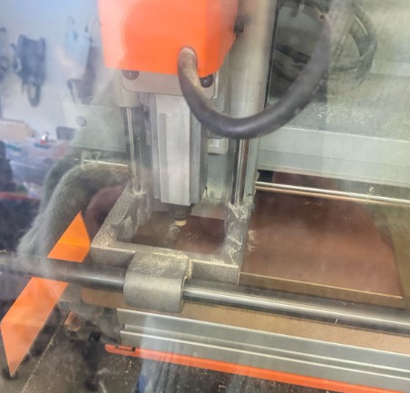
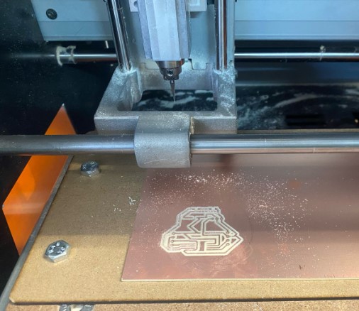
- I turned on the machine and opened the panel.
- I placed and adjusted the sacrificial bed in the machine.
- Then, I checked the tools that I was going to use.
- After that, I started by calibrating the axes of the machine.
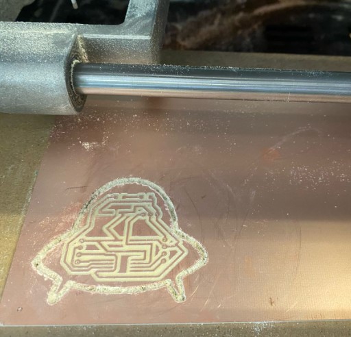
- First, I drilled the holes using the cutting tool. Then, I engraved the traces, and finally, I made the cut.
Solding my PCB
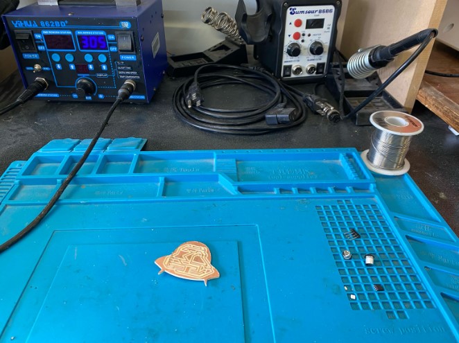
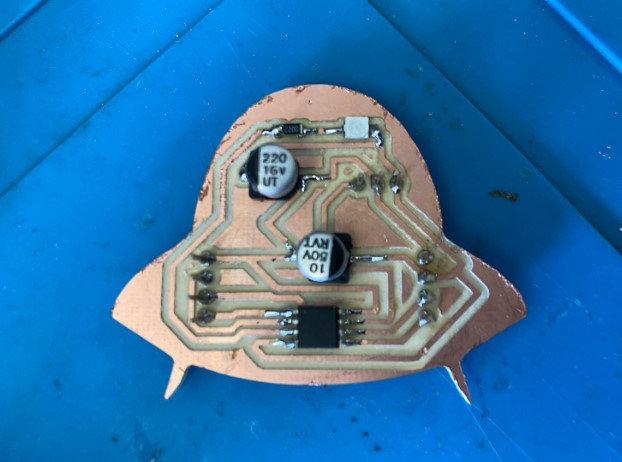
I soldered the Attiny first, then the other components, because the Attiny was delicate and I had to be careful not to join its pads.
How I Programmed an ATtiny45?
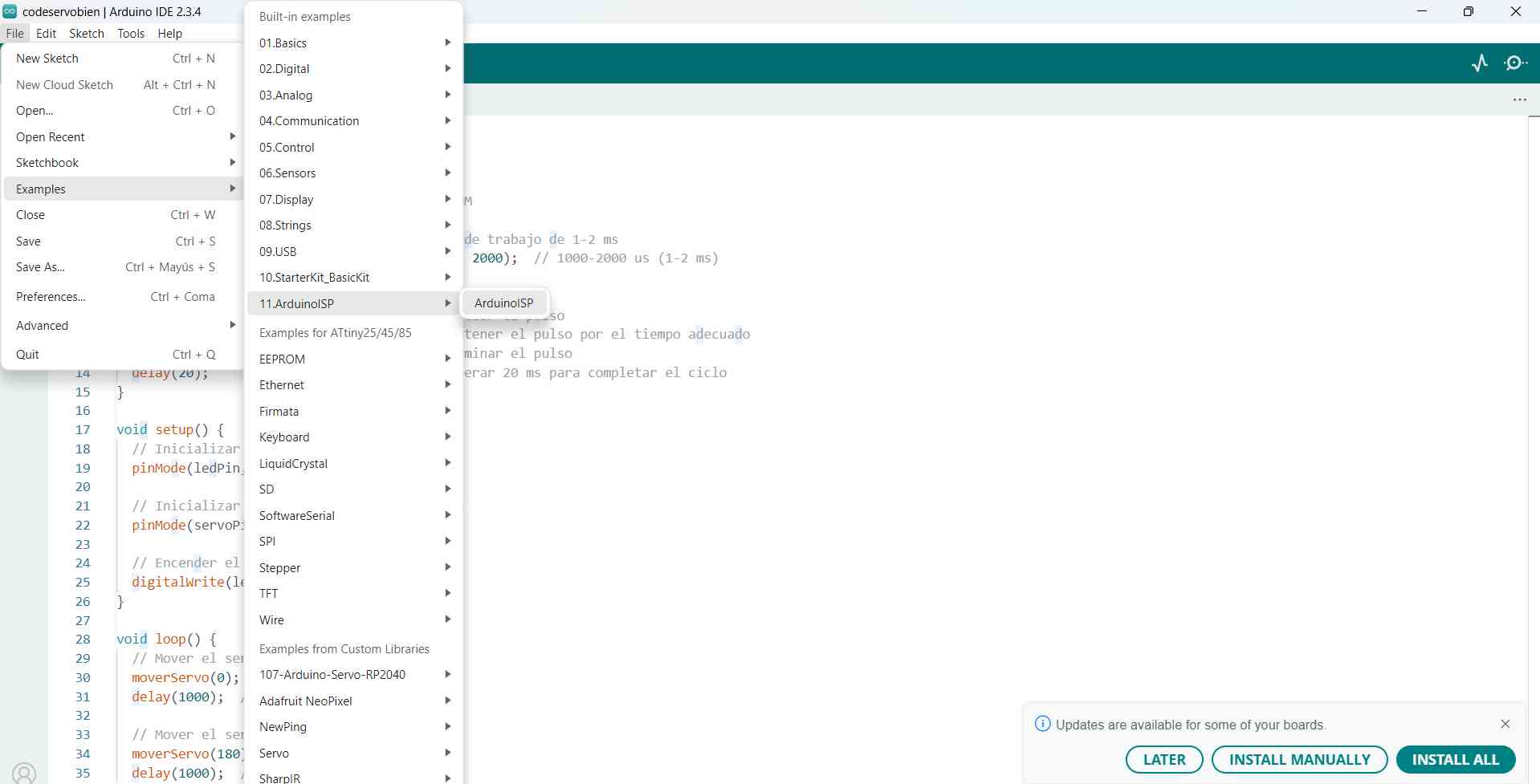
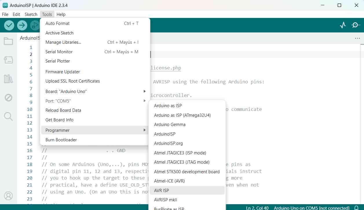
- I uploaded the ArduinoISP code with these configurations.
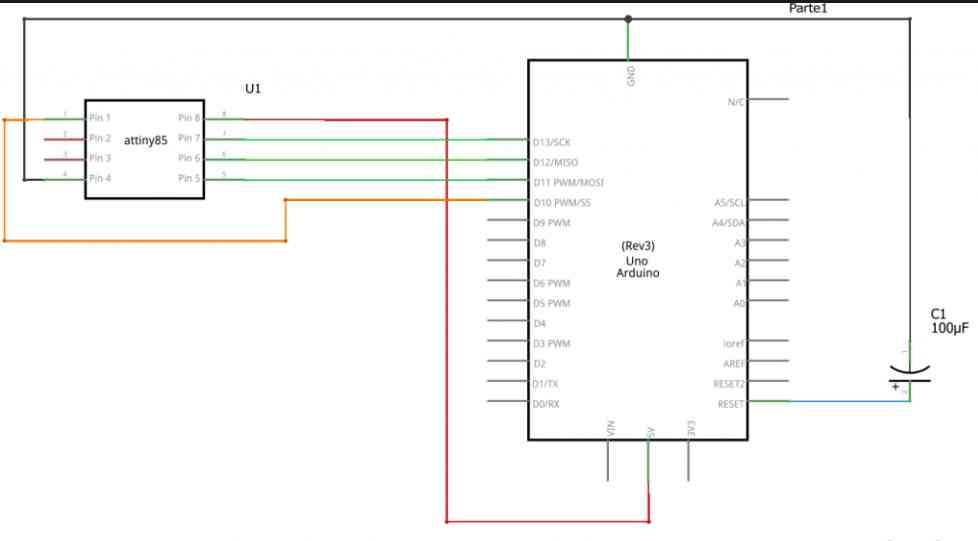
- Then, I connected the ATtiny85 to the Arduino Uno using the following diagram.
- Next, I added the following URL in the Preferences section and installed it:
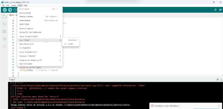
https://raw.githubusercontent.com/damellis/attiny/ide-1.6.x-boards-manager/package_damellis_attiny_index.json - Then, I applied the following configurations.
- Finally, I burned the bootloader and uploaded my code. After that, I tested my code on my PCB.
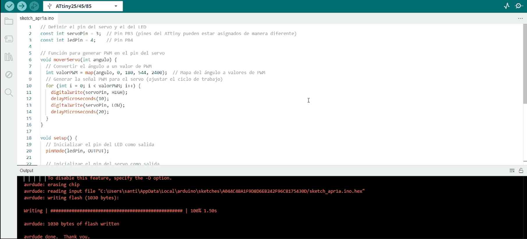
Code
// Define the servo and LED pins
const int servoPin = 3;  // PB3 pin for controlling the servo motor
const int ledPin = 4;    // PB4 pin for controlling the LED

// Function to move the servo using PWM signals
void moverServo(int angulo) {
  // Convert the angle (0-180 degrees) to a pulse width in microseconds (1-2 ms)
  long pulseWidth = map(angulo, 0, 180, 1000, 2000);  // 1000-2000 µs (1-2 ms)

  // Generate the PWM signal for the servo
  digitalWrite(servoPin, HIGH);        // Start the pulse
  delayMicroseconds(pulseWidth);       // Hold the pulse for the required duration
  digitalWrite(servoPin, LOW);         // End the pulse
  delay(20);                           // Wait 20 ms to complete the PWM cycle
}

void setup() {
  // Initialize the LED pin as an output
  pinMode(ledPin, OUTPUT);

  // Initialize the servo pin as an output
  pinMode(servoPin, OUTPUT);

  // Turn on the LED
  digitalWrite(ledPin, HIGH);
}

void loop() {
  // Move the servo to 0 degrees
  moverServo(0);
  delay(1000);  // Wait for 1 second

  // Move the servo to 180 degrees
  moverServo(180);
  delay(1000);  // Wait for 1 second
}
🛸ATtiny Troubleshooting Process🛸
First I made a first board, in which I was missing a pin so I tried to fix it with a cable but it didn't work.
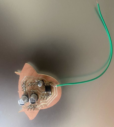
The second problem was in the new PCB, because my code didn’t upload because it didn’t recognize my ATtiny. So, I verified the soldering and the connections with a multimeter, but everything seemed fine.

My instructor explained that a microchip(Microside programmer) is used for programming. First I installed the software and set the following configurations
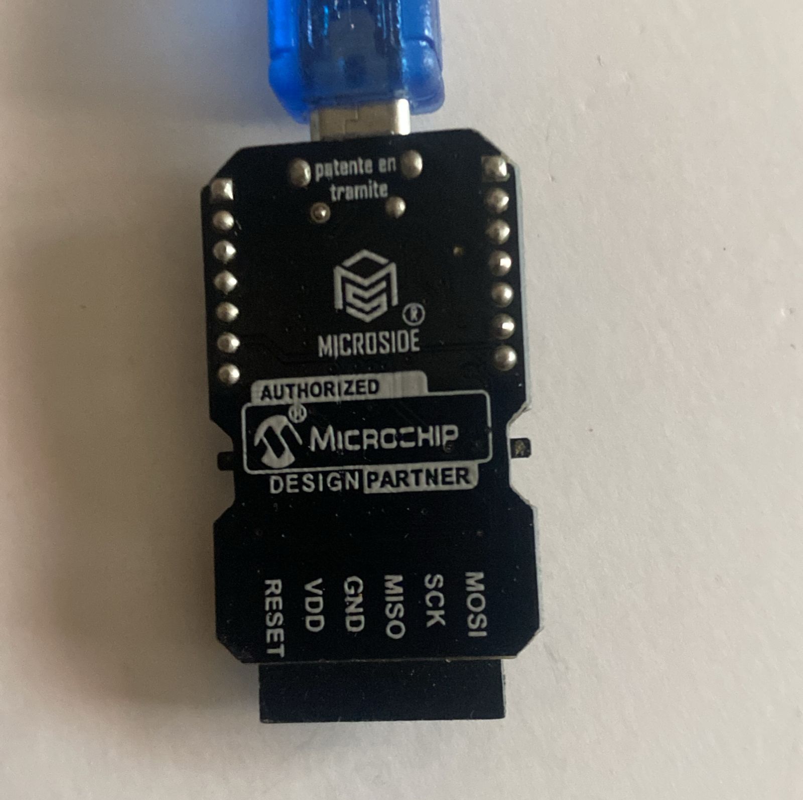
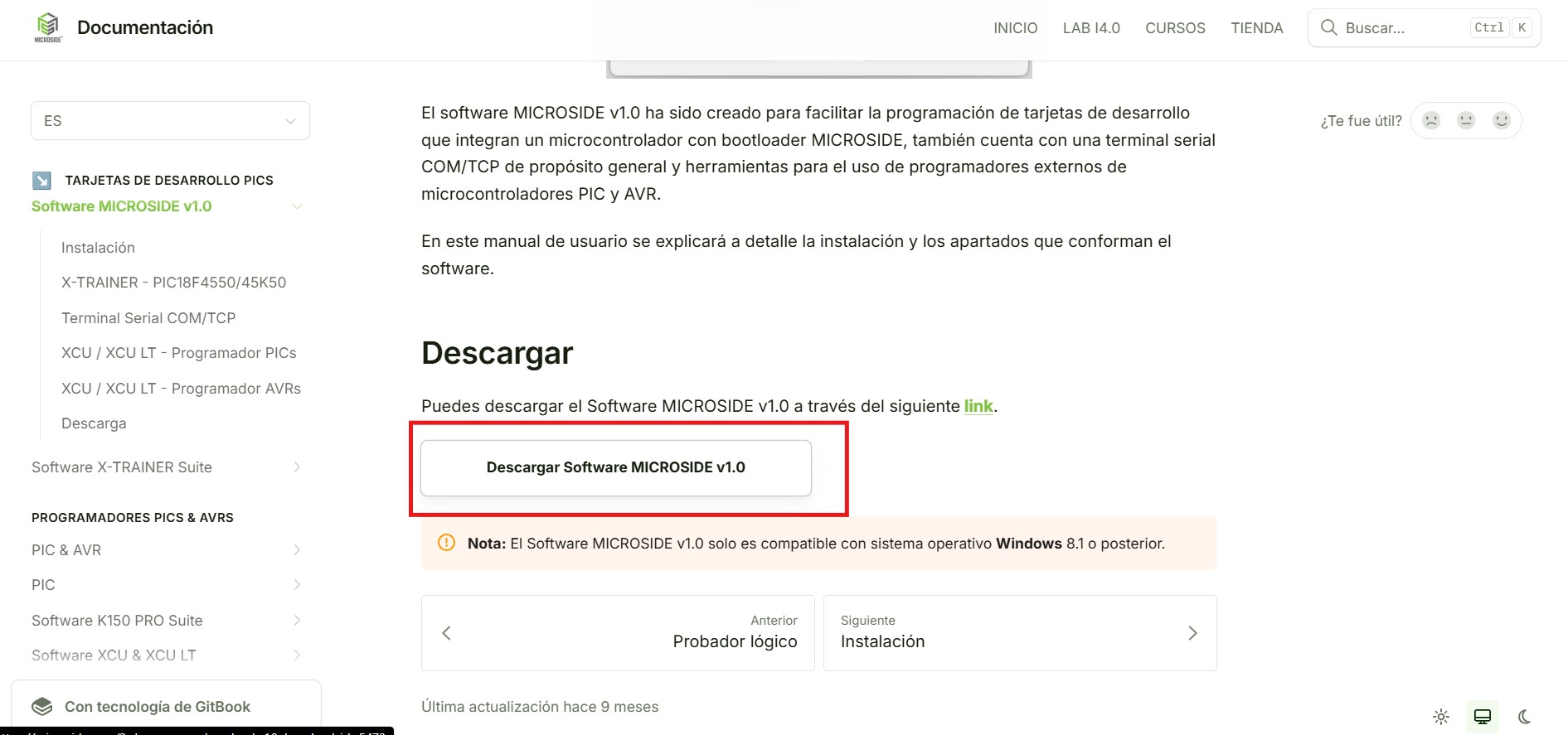
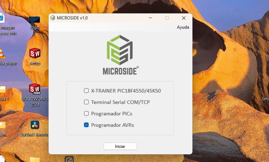
I tested it on a breadboard, and it worked.
However, when I tried using the Arduino with my Real PCB, it still didn’t work.
As a last resort, I used the microchip again to recognize my PCB, and it successfully detected the ATtiny.
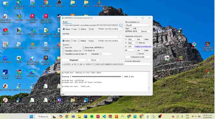
After disconnecting the microchip, I tried again with an Arduino, and this time, it worked.
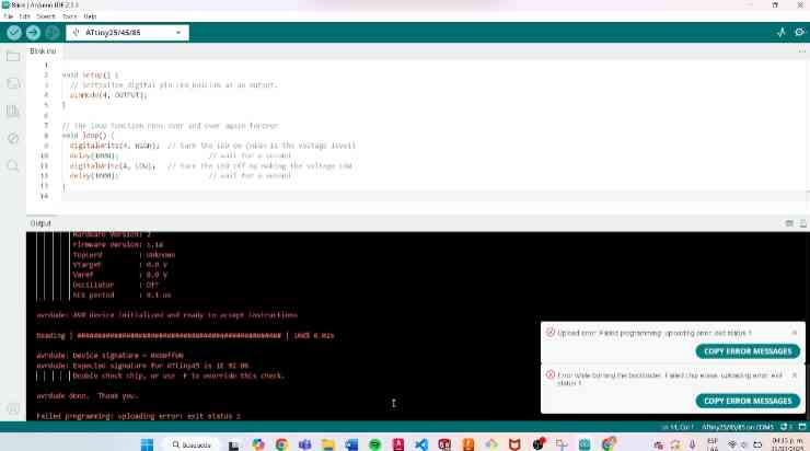

I believe I was able to program the ATtiny45 with the Microside programmer and then with the Arduino because the Microside correctly configured the ATtiny45, allowing the Arduino to program it without problems.
Files
Conclusion🛸🛸
This week was difficult for me because I tried to make a new PCB with an ATtiny45, but when I tried to load the code, it would not load the voltage. As a result, I had to design a new PCB and this one didn't support it either, but in the end I was able to program the second board and program the outputs.
