Week 15 - System integration
This week's task is to design the system integration for the final project.
I started by creating a more complete Fusion 360 model of my project:
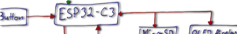
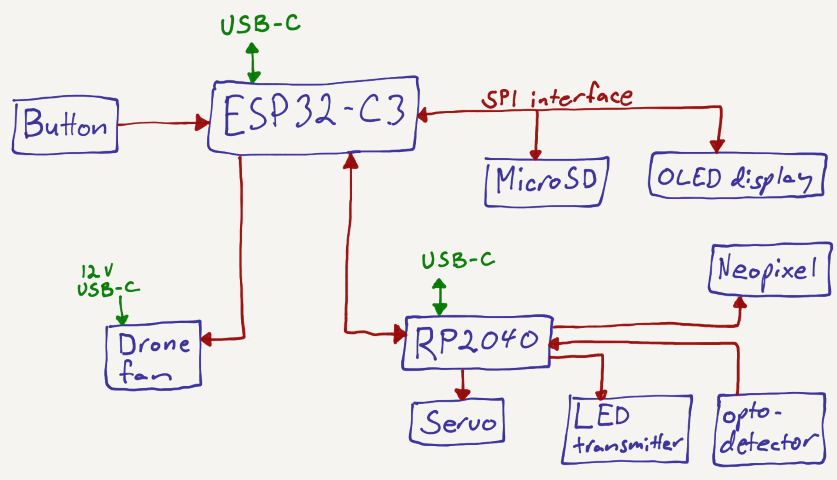
System diagram below. Mostly, I'll use TE connectivity AMP connectors hidden behind panels, secured with zip cable ties.
Some key questions to address:
The mechanics related to the bat swing must be very solid, using several ball bearing connections. Here I am testing the bat swing mechanics during Week 13. I used a pre-made bevel gear design from Thingiverse: https://www.thingiverse.com/thing:372530
Update: I extruded and extended the bevel gear enclosure to be able to control the bat from the side of the game. This design proved very solid and nice feeling.
- Display testing and software development have only just begun. Update: Finished, working with no issues.
- How can the whole structure be made solid and stable? Using aluminum profiles is tempting. Update: After all, I decided to use the enclosure, which I designed during week 7, which is nice and stable.
- Clear plastic is needed to see into the playing field. I'll add grooves to hold them in place. Update: Added these to the cnc-model of the enclosure.
- Is 15 mm birch plywood (koivuvaneri) suitable for the bottom plate? Update: Used 11 mm OSB, which was OK after sanding the rough edges and black painting.
The servo and target loop should stand on their own stable leg, connected to the bottom plate. The back plate will fit over and around this structure.
Update after week 15:
I combined all of the individually designed Fusion 360 models into one complete assembly using the “Insert into Current Design” option from Fusion 360's Data Panel. This resulted in a 50 MB file. To make it suitable for uploading to the Fab Academy repository, I reduced the file size to 10 MB by breaking the component links, deleting the timeline history and putting the bevel gear system in a separate Fusion 360 file (see below).
Below is an animation of the full model, where you can see the tapered gateway I created for the ball to fly through, as well as the downward-sloping structures designed to ensure the ball always returns in front of the fan. I also added a second backboard to enclose the electronics and power supplies. The OLED display was embedded into this secondary backboard.
To laser cut the secondary backboard, the OLED display holder plate, and the downward-sloping plane, I needed to generate PDF files containing their outlines. In Fusion 360, I first used the Isolate command in the Browser to focus on each part individually. Then, I used the P key to project the components' 2D geometry onto a new sketch. This created sketches that matched the shapes of the boards to be laser cut.
I right-clicked each sketch in the Browser and selected Export DXF. I then opened the DXF file in Inkscape and saved it as a PDF with a line thickness of 0.02 mm, which is suitable for laser cutting. I followed this same method for the secondary back board, OLED display holder and the sloped plane that guides the ball in the playing field.
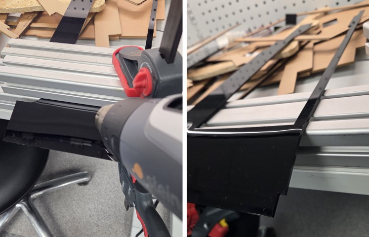
I bent the acrylic plate at the top end to reduce the angle, by clamping it in place, heating it with a hot blower, and bending it once it became soft.
Methods of Packaging:
As shown above, the plan was to place the power supplies and electronics behind an intermediary backboard. According to the Fusion 360 model, there should have been about 1 mm of space between the main backboard and the rearmost servo component. However, I had forgotten that I added washers to the servo to make more space for the ball bearings. As a result, there wasn't enough clearance to fully close the backboard. That said, since the game is intended to sit on a shelf, the current setup is acceptable.
The PCBs were placed in their own dedicated spaces behind the game, and the wires were bundled neatly using zip ties. Below is a video showing how the electronics were packaged behind the game:
Design files
Full 3D device integration Fusion 360 file (excluding bat bevel gear holder, see below)
Bat bevel gear holder, gears, ball bearing adapters, and knurled knob Fusion 360 file. Adapted from a design by David Kirbis.
Laser cutting file for the plate around the OLED display
Graphics UV-printed on the plate around the OLED display, including my signature, which was written on an iPad and imported into Inkscape using the Trace Bitmap tool.
Alignment graphic for UV-printing on the plate around the OLED display
Laser cutting file for the downward-sloping plane on the playing field
Laser cutting file for the secondary back plate with laser engraved audiences based on ChatGPT prompts "outline, row of people cheering on a stadium bench" and "some other types of people, narrow version?"
Bat bevel gear holder, gears, ball bearing adapters, and knurled knob Fusion 360 file. Adapted from a design by David Kirbis.