Week 7 - Computer controlled machining
This week's group work, with Stanley and Shahmeer, was to complete our lab's safety training, and to test runout, alignment, fixturing, speeds, feeds, materials and toolpaths for our Rensi e2-1325 CNC (computer numerical control) milling machine. I'm now familiar with the procedures for operating the machine.
The individual task was to design and manufacture something big with a CNC router.
I started having doubts whether my final project might be even too big to be practical? I decided to do some testing with a hair dryer to see how large playing field would actually be required. Based on this test, it seems that a good distance for the target in the game is about 250 mm, and therefore the total size of the game should be about 600 mm (width) x 300 mm (depth) x 450 mm (height), which doesn't seem too big.
3D design
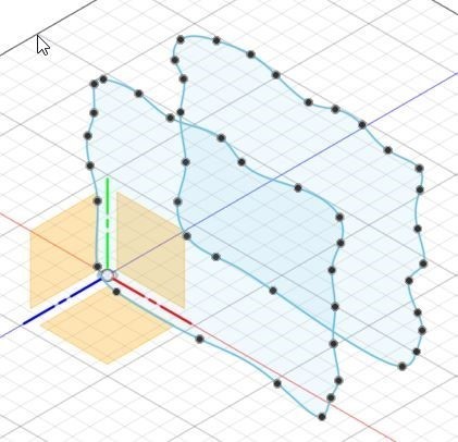
I wanted to design a cool-looking exterior for my game. I really like the parametric wall art available on Etsy, so I tried to create something similar for my game. I started creating the casing for my final project by making two sketch blobs on two different planes.
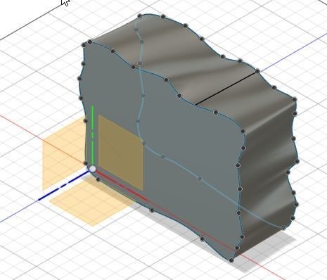
Connected them with a loft:
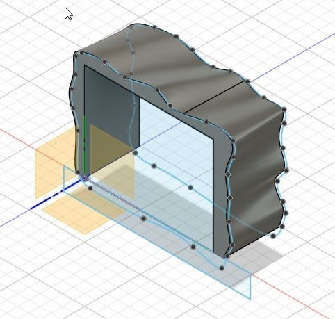
I made an inner central space for the game:
I individually created square sketches and used the 'Project Intersect' tool to intersect them with the blob. Then, I used the selection filter set to 'Bodies'.
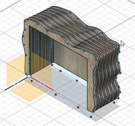
I extruded the intersecting shapes by 11 mm and created new components out of the wavy boards. This process required a lot of manual work, there's probably a more efficient way to do it.
To create the connecting pieces for the boards and attach them to the bottom plate, I asked ChatGPT: 'I have a board that needs to go "through" other boards in Fusion 360. How can I easily create holes in the other boards?' I received a suggestion to use Modify → Combine → Cut, which worked nicely. Finally, I arrived at the following model for the game casing:
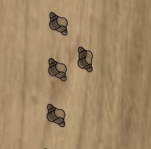
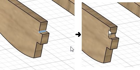
I also installed and used the Dogbone Fusion 360 add-in to create dogbone joints for the wood joinery. By milling the edges deeper in this way, the roundness of the milling bit is compensated for, allowing a sharp-edged tab to fit into these pockets.
For some edges I got this error:
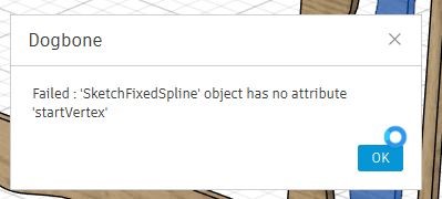
The fix was to manually choose all edges to be dogbone-processed:
Creating NC Files for CNC Machining
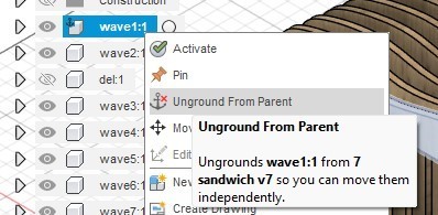
To prepare the design for manufacturing, the parts need to be laid out in the XY-plane. One component was grounded to its parent, which I first removed.
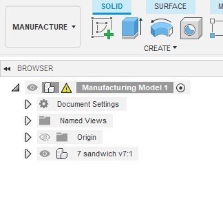
Additionally, all bodies needed to be converted into components. I then created a manufacturing model in Manufacture mode and opened it.
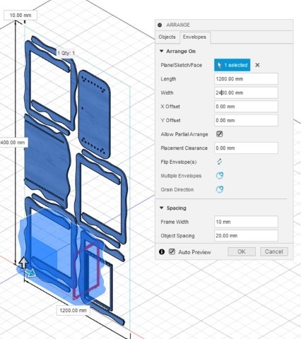
I then selected Modify → Arrange in Design space and chose the components to be CNC-machined. In the Envelopes tab, I selected the Y/X plane.
My biggest mistake this week, which caused a lot of problems, was choosing the wrong length and width for the arrangement. For our CNC machine, unintuitively, the length is 1197 mm, and the width is 2600 mm (though I’m still not entirely sure about this). Another problem was that not all components fit on the board: one part, shown in dark red, did not fit. I decided to CNC mill only half of the components first.
Creating a Manufacturing Setup
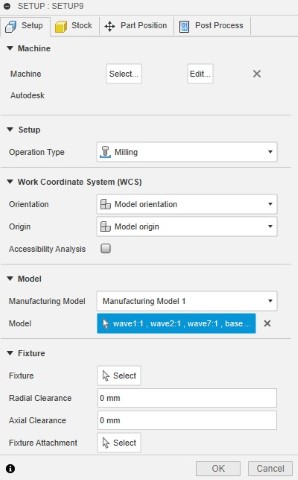
A manufacturing setup defines what you want to machine and how it will be machined. I followed Antti's instructions to create the setup:
In the Manufacture workspace, I clicked Setup → New Setup. I selected the FabLab machine, which had been installed previously, and chose the components to be manufactured in Model:
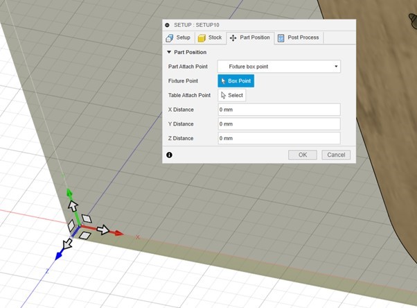
In the Part Position tab, I moved the stock point to the bottom corner like this:
2D Pocket Settings
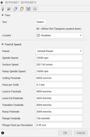
For milling pockets (holes that don’t go through the board), I chose the following settings. In the first tab, I selected a tool:
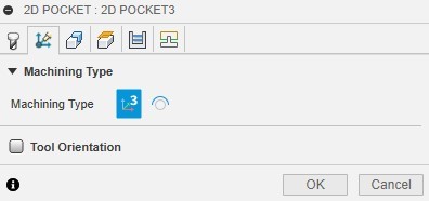
Multi-Axis tab, no changes:
Geometry tab, I selected the pockets with the mouse and put in tabs:

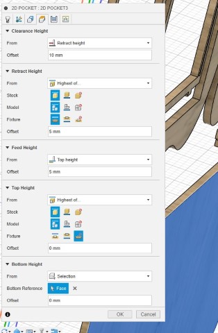
Heights tab, a few changes, and I selected the bottom face:
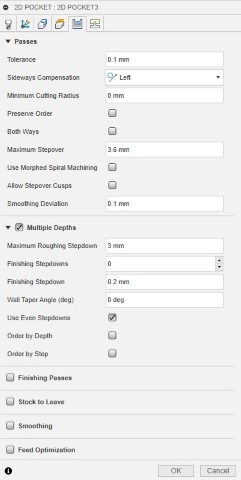
Passes tab:
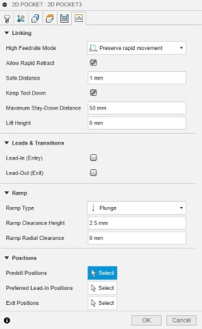
Linking tab:
2D Contour Settings
For milling contours (outer edges of board pieces), I chose these settings:
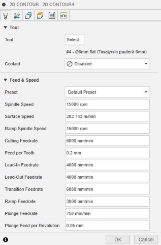
Tool tab settings:
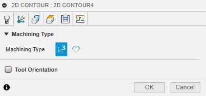
Multi-Axis tab, no changes:
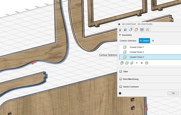
Geometry tab, I selected the bottom edges of the contours to be milled:
Clearance Heights:
![]()
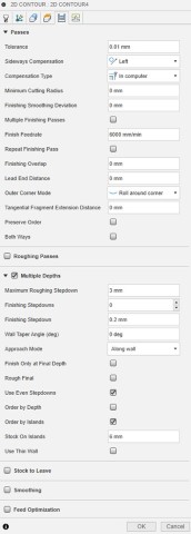
Passes tab, several changes:
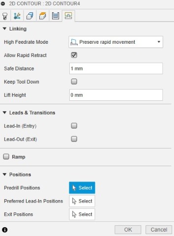
Linking tab, a few changes:
Post Processing
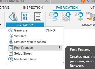
After completing all the toolpath settings, I performed post-processing to generate the G-code. A separate G-code file was created for pocket milling and another for contour cutting. If different mill widths are used, additional files are generated for each tool to allow for tool changes during the CNC process.
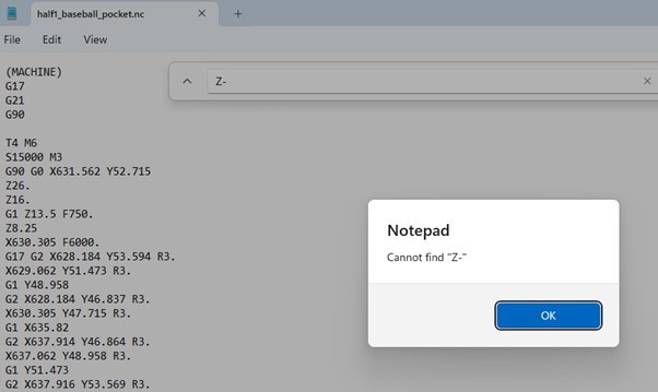
G-code (geometric code) is the most commonly used language for CNC machines. G-code commands instruct the machine where to move, how fast to move, and along what path. It is important to verify that there are no unintended negative Z-values in the G-code, as these could cause the milling bit to cut too deep into the sacrificial layer:
I saved the .nc file from my computer to a USB stick to be loaded in the next step:
CNC milling
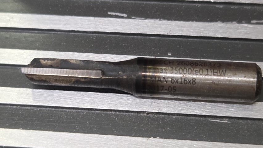
I used a 6 mm milling bit:
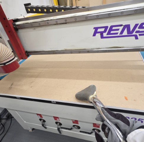
Vacuumed the sacrificial wood layer:
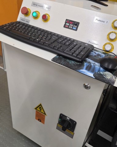
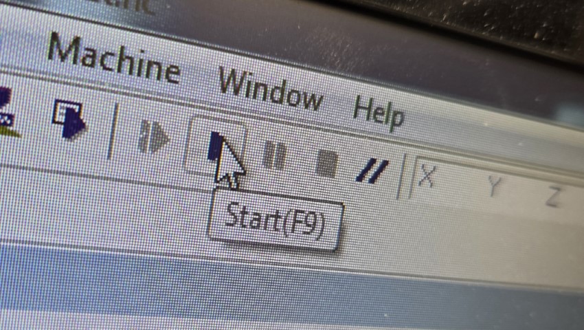
Started up the machine and NcStudio program.
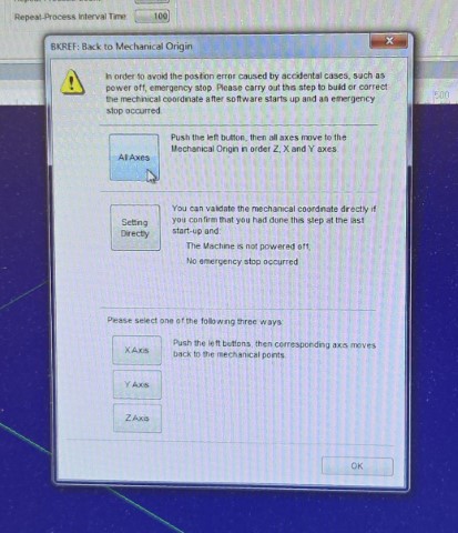
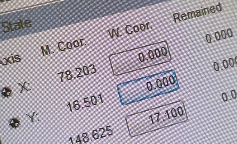
Moved to the mechanical origin:
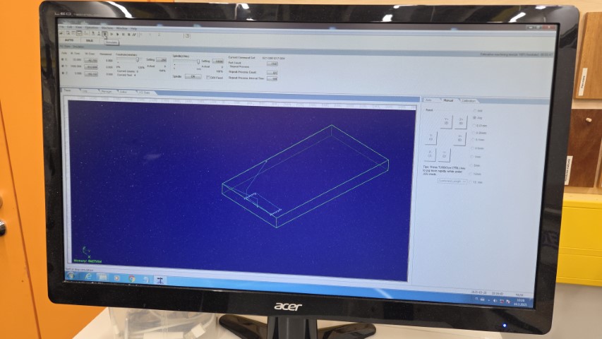
Loaded an .NC file created in the previous step and simulated it:
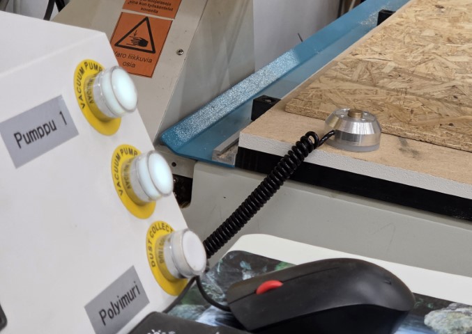
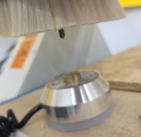
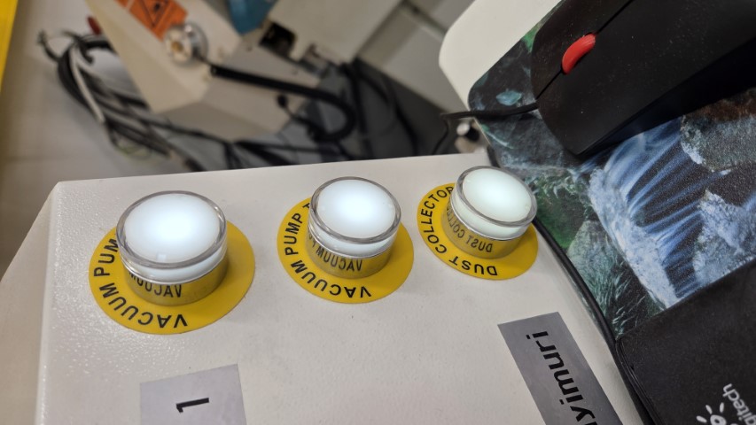
Turned on the pumps and placed the mobile calibrator on the sacrificial wood layer:
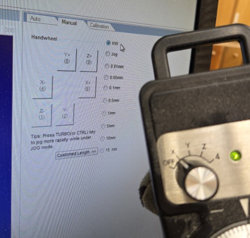
Moved the milling bit manually:
Aligned the milling bit in the X and Y directions above the mobile calibrator:
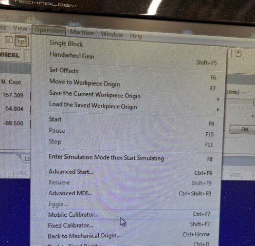
Started the mobile calibrator procedure:
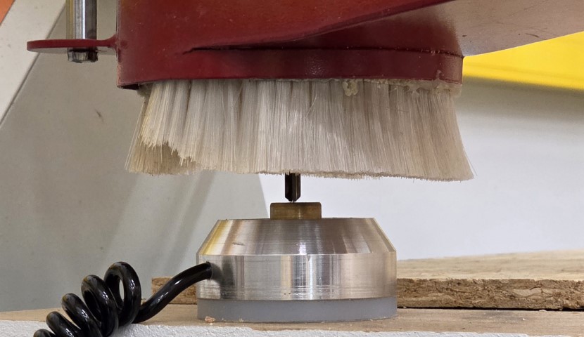
…which slowly lowered the milling bit until it touched the mobile calibrator, calibrating the Z-direction:
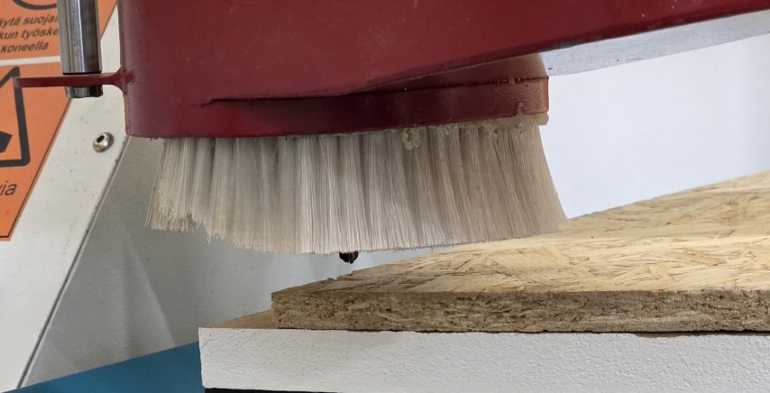
Moved the milling bit to the lower-left corner:
…and zeroed the X and Y coordinates:
Turned on the milling vacuum:
Placed a plexiglass guard in front of the mill and started the milling process.
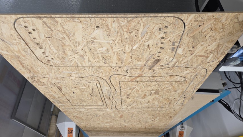
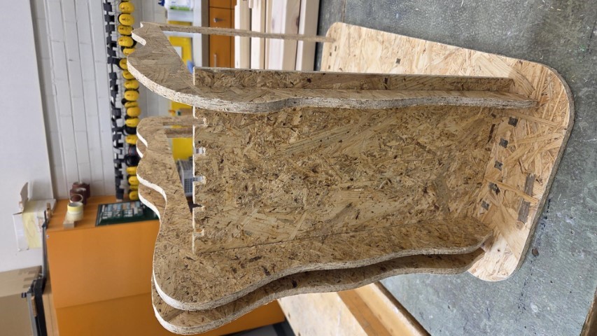
The result after milling the contours and pockets for the first half of the components:
Sanded the rough edges:
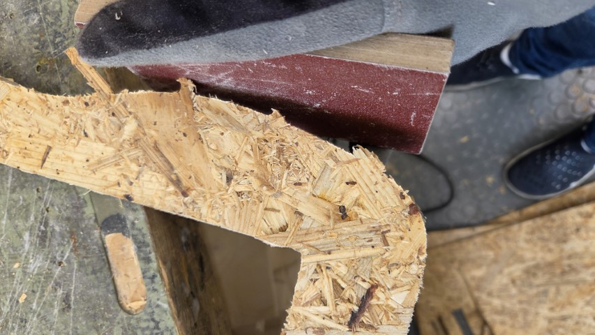
Final result of the first half of the components:
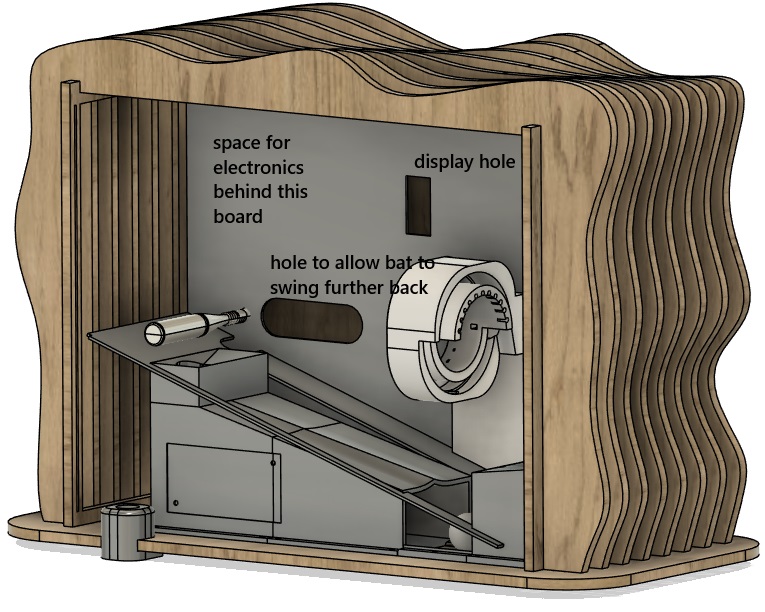
At this point, I realized that there wasn’t a good enclosed space for the electronics of my game behind the playing field. Therefore, I decided not to print the remaining components, as I'll redesign and perform another CNC milling of the game's casing later.
Update after week 4
After designing all of my game elements, I realized that I could fit the game into a tighter space than originally planned. This allowed me to place a laser-cut MDF board in front of the backboard, creating a 556 × 65 × 510 mm compartment to hide the electronics and power supplies. I proceeded to CNC-mill the enclosure as previously planned.
I spray painted the enclosure black:
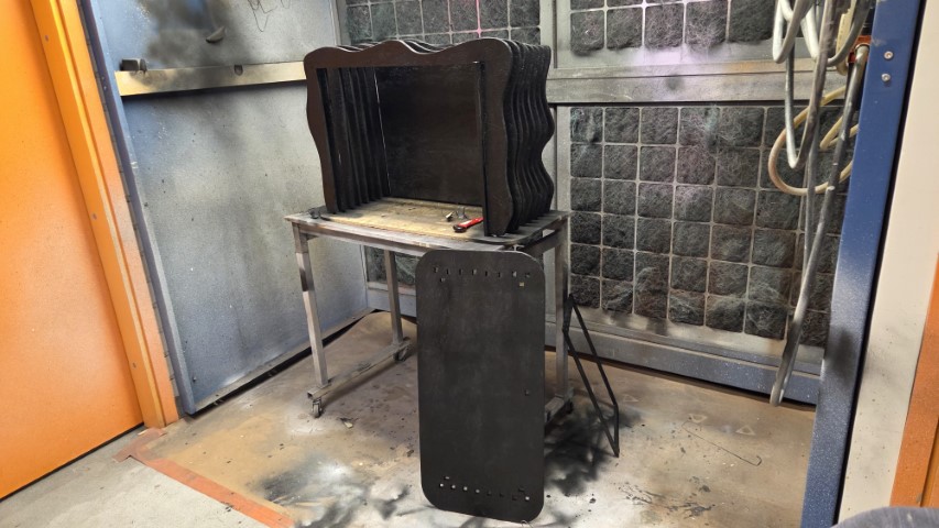
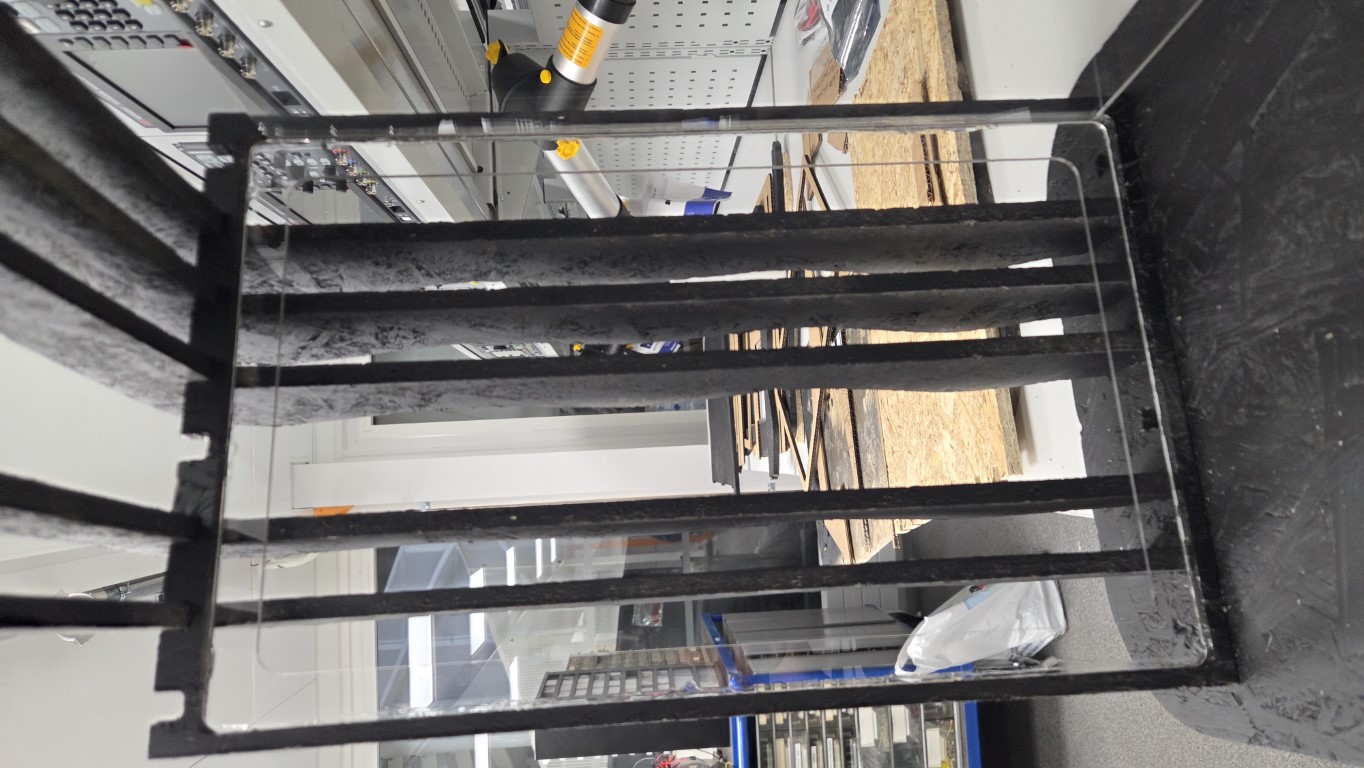
However, there was one issue. While trying to create 3.1 mm wide grooves to hold the 3.0 mm thick front transparent acrylic plate, I had set a milling parameter incorrectly in Fusion 360. As a result, one of the side supports ended up being only half as thick as intended and couldn't properly support the top boards. To fix this, I laser-cut and glued an additional acrylic plate to reinforce the overly thin side support. This solution worked well and restored the structural integrity.
Potential improvements
A potential second version of this enclosure should be parametric, allowing the dimensions and material thickness to be adjusted afterward. During Week 3, I was planning to create an enclosure that transforms as the game progresses, but it would have been difficult to achieve a well-operating system within the available timeframe.
To avoid the mistake made while milling the side boards that hold the transparent front plastic, I should have selected the bottom of the cut geometry in the Heights tab of the 2D pocket milling operation: not the stock's bottom, unless the intention is to cut all the way through.
Design files
Full device integration Fusion 360 file, including the 3D model of the enclosure