
Week 3 - Computer controlled cutting
This week, Neil, Behnaz and Gleb introduced us to laser cutters and vinyl cutters. As a group work with Stanley and Shahmeer, we first got a safety training and then conducted investigations with our Epilog Laser Fusion 75 W laser cutter to find the optimal laser power and speed settings for different materials, examine the effect of laser focus, and measure the kerf (the portion of material that the laser burns away when it cuts through). I got into the routine of setting up the laser cutter and developed an understanding of the kerf and how to compensate for it in designs.
For my individual work this week, I designed, laser-cut, and documented a kerf-compensated parametric construction kit to decorate my final project, which I want to resemble a small stadium from the outside. Another task was to cut something with the vinyl cutter. I used it to create stickers, which I attached to the parametric construction kit. Additionally, I designed a decoration for the top of the "stadium," which I plan to make motor-driven. These elements are described in the following sections.
Kerf-compensated parametric construction kit
To decorate the sides of the “stadium”, I designed a laser-cut hexagonal parametric construction kit using 2.5mm medium-density fibreboard (MDF).
To begin, I created a sketch in Fusion 360 using the 'Create' menu to generate a six-sided circumscribed polygon. I defined the polygon’s size using a parameter, hexagon_radius, initially set to 40mm. Next, I placed a three-point rectangle on one side with a depth variable, cut_depth, and a width equal to board_thickness - kerf.
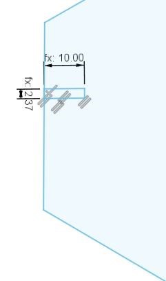
Next, I applied a midpoint constraint and a parallel constraint to the edge of the rectangle to be cut. Then, I used the Create → Circular Pattern tool, selecting the three-point rectangle edges as “objects” and the center of the hexagon as the center point. I set the quantity to 6, ensuring that the cut pattern was evenly distributed across all six faces of the hexagon. As a result, the outline of the holes was successfully replicated on all sides of the hexagon.
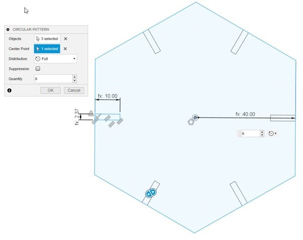
At this stage of the design, I struggled to continue without breaking the existing constraints while ensuring that the parameters remained functional. My main mistake was assuming that the small lines at the edges of the holes (with widths of "fx: 2.37" in the above image) needed to be deleted from the hexagon sketch. However, I later realized that these lines can remain in the sketch without affecting the extraction of the hex piece.
I wanted to create small connecting pieces for my stadium decoration to link the hexagons. I designed two types of interconnections—one straight and one slightly curved (as shown in the next image)—using the same design procedures as the hexagons.
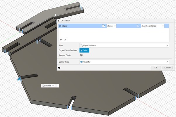
To make assembly easier, Neil suggested adding a chamfer to the entrances of the interconnecting holes. This was done in the Solid Design tab after extruding the sketches by an amount equal to board_thickness. I selected each edge to be chamfered and then applied the Modify → Chamfer tool.
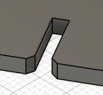
Here is a close-up view of one entrance hole after chamfering.
Overall, I defined seven parameters that can be adjusted—for example, to accommodate a different board thickness. Updating these parameters automatically modifies the design accordingly:
Next, I generated a 2D PDF file suitable for our laser cutter using Fusion 360. To do this, I created a new sketch and selected the top face of one of the pieces. In sketch mode, I navigated to Create > Project/Include > Project, then clicked on all the faces I wanted to include in the 2D PDF file and clicked 'OK.' After finishing the sketch, I selected it with the right mouse button and chose Export DXF. I then opened this DXF file in Inkscape and modified the line widths to 0.02 mm, as this specific width indicates cutting lines for our laser cutter, and saved as PDF.
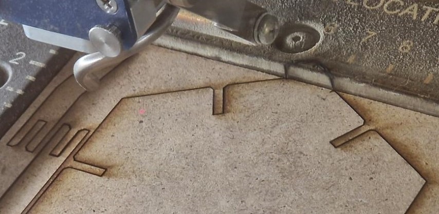
I opened the PDF and printed it using the Epilog Engraver WinX64 Fusion laser cutter. I selected the predefined settings in the Advanced tab based on the material. To set the focus, I placed the triangular focusing tool on the laser head and adjusted the height of the board in the Focus menu until the board barely touched the tool. I then confirmed the focus by pressing the joystick. In my first laser cutting trial, I forgot to confirm the Origo point by pressing the joystick in the upper-left corner of the work area in the Jog menu. Because of this, the Origo was outside the print area, causing the laser cutter to move beyond the designated print area:
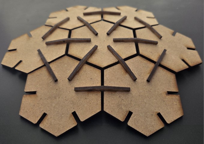
After testing different kerf values, I finally achieved a good fit and proceeded to laser cut a full set of pieces:
The pieces can be connected in various ways.
Vinyl cutter
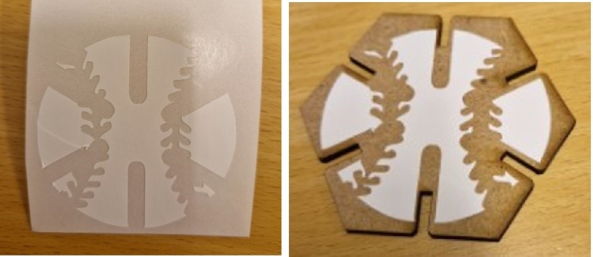
To decorate the parametric construction kit, I tried to create a baseball-themed sticker with Roland CAMM-1 GS-24 vinyl cutter to attach to one of the hexagon pieces. I took a simple picture of a baseball, made it transparent, and imported it into Inkscape. Using the Trace Bitmap tool, I detected the image’s outlines with Trace bitmap in Path menu, changed their color to black, and removed the fill. After removing the original baseball bitmap (seen on the right in the following image), I added six holes at the edges of the design to fit the connecting hexagon pieces. Finally, I ensured that all cut lines were set to 0.02 mm.

Next, I used the vinyl cutter to cut the sticker. The result was not as impressive as expected. The space was quite cramped due to the hex attachment pieces, and the .SVG file had overlapping lines, making the processing of the sticker more difficult, and I applied the prespacing paper incorrectly.
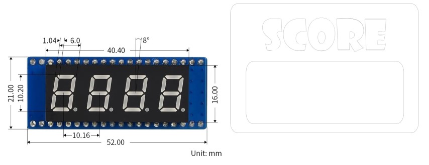
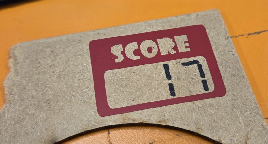
I decided to do another vinyl cutter design, to label the score display of my final project. I plan to use something like the display shown in the following image on the left side. I created the vinyl cutter outline shown in the right side of the image in Inkscape to place on top of/around the score display.
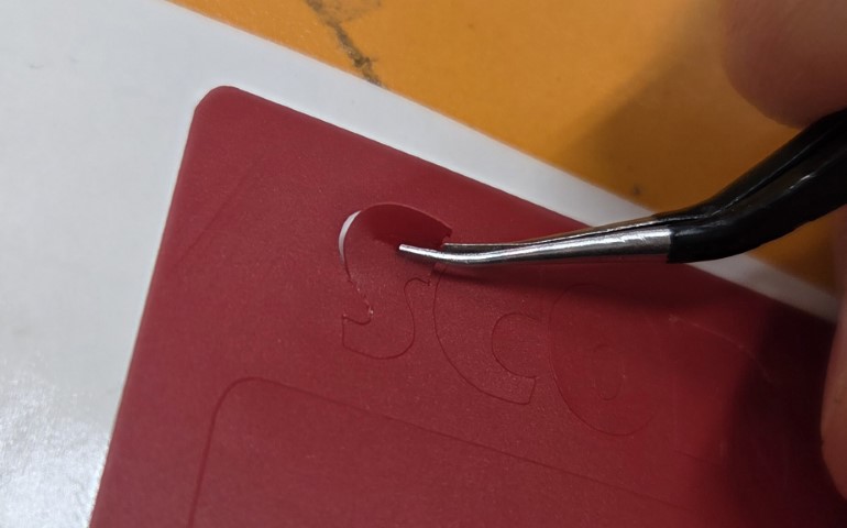
Next, I launched the Roland Cut Studio extension and loaded the sticker material into the vinyl cutter (the lever can be opened from the left), making sure the rollers were aligned with some of the white stickers. I selected "roll" from the machine. I positioned the cutter at the desired location and set the origin by long-pressing the 'Origin' button. I set the cutting force to 90 gf. After cutting I took out the unnecessary pieces from the sticker away with tweezers, pressing against a table:
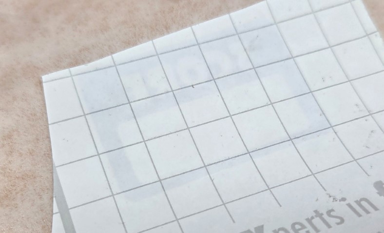
I then pressed the sticker upside down onto a prespacing paper:
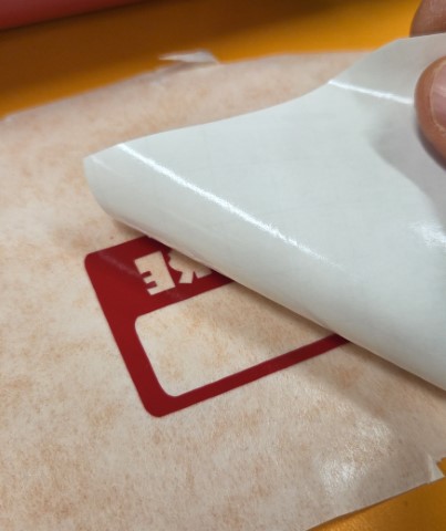
Then I took off the paper, which originally was on the back of the sticker:
Now I could press the sticker on the target surface and peel back the prespacing paper:
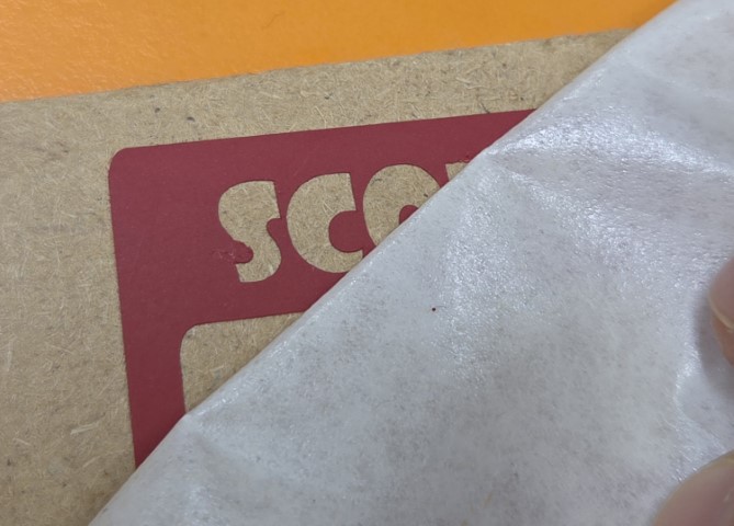
Now, I have a prototype of the score display. I should have been more careful not to lose the center hole of the letter 'R,' and perhaps increasing the vinyl cutter force slightly would have resulted in cleaner cuts.
Kirigami Experiment with a Laser Cutter
For my final project, I want to design a game that resembles a small stadium from the outside. Inspired by modern stadiums, I thought it would be interesting to create a large kirigami (origami with cuts) honeycomb pattern that opens up on the roof as the game progresses. I found the following pattern on Origami Simulator, which I might be able to use.
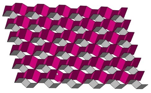
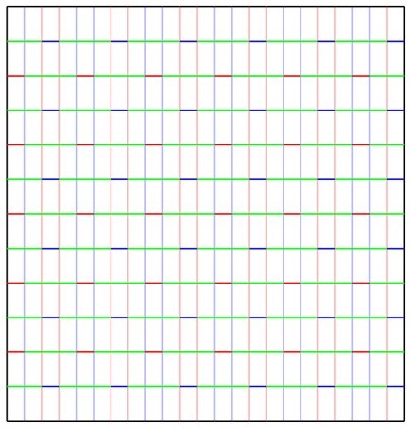
I downloaded the following pattern for the kirigami design from Origami Simulator. Green lines indicate cutting paths, while other colors represent folds in different directions.
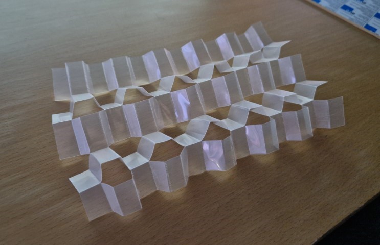
The cuts were made using predefined settings originally designed for regular thin paper. The laser power for the folding parts could have been higher to create better folds. Here is the laser cutter in action, making the folding parts:
The kirigami design works, but the material is too flimsy. If I proceed with my plan to place a motorized origami/kirigami structure on the roof of my project, I will need a sturdier material that still bends. This could be achieved, for example, with a fabric attached beneath cut pieces of wood or with partly cut wood.
Design files
The Fusion 360 design file for the hexagonal piece and connectors
.SVG file for the hexagonal piece and connectors