Week 11 : Networking and Communications
This week is networking and communications week. We were individually tasked this week to design, build, and wired or wirelessly connect node(s) with network or bus addresses and local inputs and/or output devices. As well as a group task of sending a message between two projects. Not going to lie, this week feels like we went from swimming with floaties in a small pool to scuba diving in the Pacific Ocean.
Connecting Nodes with Network
To take on this week’s daunting task, I utilized tools and components that would help make this deep scuba dive trip into more of a snorkeling in the shallows type trip. Sorry for the continued analogy, but I think it helps get my point across. I have barely touched the surface of networking and communications and still barely understand it, but with somewhat accessible tools and ever evolving tech and can achieve our task and have a place to start.
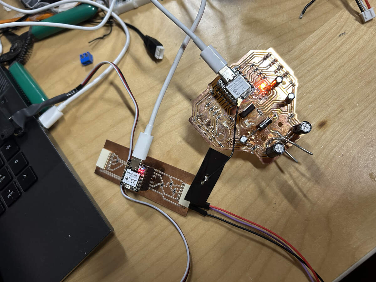
- I first chose what method of communication with which microcontroller would be the easiest to work with. Getting advice from mentors, the route I chose was to use a Wi-Fi connection by way of the XIAO ESP32-S3, which already has Wi-Fi capabilities built in.- My final project did not initially have a use for networking or communications, but I wanted this week to have the possibility of tying into my final if desired. A task I thought would be useful is to have a count of every time the motion sensor is triggered, sent to a site. This would be useful data for me to collect and see how many people are stopping by my booth at shows or markets.
- Running into problems started before we even got to new content. For some reason I have been struggling to get my microcontroller to be recognized by my computer. I’ve been trouble shooting for quite a bit and still can’t seem to find the issue. Without a functional controller, I can’t really run any tests or codes.
- I’m positive I have missed something or over thinking it, so I decide to step away for the time being to take a breather and get some code lined up to test.
- I take the code I currently have set up for my RP2040 and ask Mr. Chat gpt for assistance on how to adjust my code for an ESP32s3 and to be able to connect to a web server that counts and displays on the server the number of times the switch has been triggered.
"Hello, I have this code for an RP2040 ( providing previous code ) Can you please help me write same function code for an ESP32s3. I would also like to use the ESP32s3 to be able to connect to a web server that counts and displays on the server the amount of times the switch is triggered"
#include < WiFi.h >
        #include < WebServer.h >
        #include < Servo.h >

        const char* ssid = "YOUR_SSID";
        const char* password = "YOUR_PASSWORD";

        // Pins
        const int switchPin = 7;     // Button pin (GPIO7)
        const int servoPin = 8;      // Servo pin (GPIO8)

        Servo myServo;
        WebServer server(80);

        int pressCount = 0;
        bool lastButtonState = HIGH;
        int var = 0;

        // Web page handler
        void handleRoot() {
          String html = "< html >< body >< h1 >Servo Trigger Counter< p >Times Triggered: ";
          html += String(pressCount);
          html += "";
          server.send(200, "text/html", html);
        }

        void setup() {
          Serial.begin(115200);

          // Pin setup
          pinMode(switchPin, INPUT_PULLUP);
          myServo.attach(servoPin, 600, 2400);

          // WiFi connection
          WiFi.begin(ssid, password);
          Serial.print("Connecting to WiFi");
          while (WiFi.status() != WL_CONNECTED) {
            delay(500);
            Serial.print(".");
          }
          Serial.println("\nWiFi connected. IP address: ");
          Serial.println(WiFi.localIP());

          // Web server setup
          server.on("/", handleRoot);
          server.begin();
          Serial.println("Web server started.");
        }

        void loop() {
          server.handleClient();

          bool currentState = digitalRead(switchPin);
          if (lastButtonState == HIGH && currentState == LOW) {
            pressCount++;
            var = 0;

            while (var < 4) {
              // Move 0° to 90°
              for (int pos = 0; pos <= 90; pos++) {
                myServo.write(pos);
                delay(10);
              }

              // Move back 90° to 0°
              for (int pos = 90; pos >= 0; pos--) {
                myServo.write(pos);
                delay(10);
              }

              var++;
            }

            delay(200); // Basic debounce
          }

          lastButtonState = currentState;
        }
- I still don’t fully comprehend the inner workings of micro controllers in general, and even more the ESP32s3 having built in wifi but, I was able to comprehend the breakdown that Chat gpt provided in the code.
-“const char*” section filling in what wifi network and password is being used
-“handleRoot” which is the web page handler/setup
-“wifi.begin” and “Serial.print” to have a visual representation of knowing when the board is connected to the wifi.
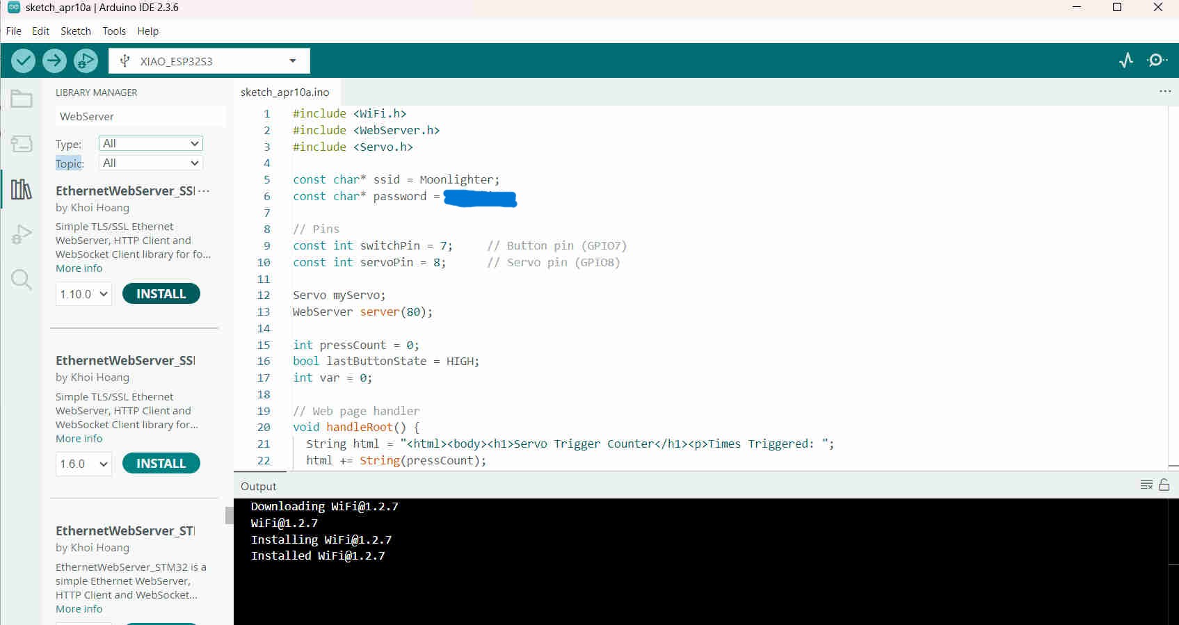
- I placed the code into Arduino IDE. When I verified it. I apparently had the incorrect webserver library. I had used one that was in Arduino thinking it was the correct one. Augusto pointed me in the right direction since he had also just gone through this himself.
- Round two. The webserver is good but silly mistake, I forgot to change the servo library from the RP2040 to the ESP32s3.
- Once the code was verified. I plugged in the controller and what do you know, my computer actually reads it. I don’t think I did anything different to get it to recognize the controller, but that doesn’t mean I didn’t. I’m just glad it connected.
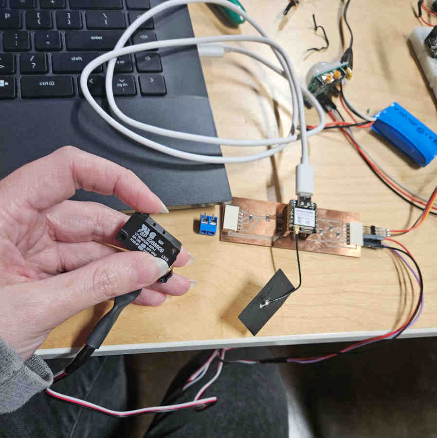
- Next hurdle. Code should be good, but I don’t seem to be connected to the wifi. Did I fry my controller? Most likely not since my computer does recognize it. Is it my internet or the antenna isn’t working. Augusto let me test my code on his controller that has been working for him. Immediately I got to connect to the wifi! So now I know the antenna is the problem but I don’t have an additional one to replace it. I will order extra, but for now to complete this week’s tasks, Augusto graciously let me borrow his for the time being.
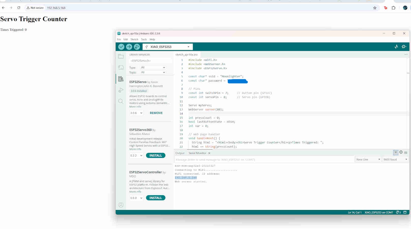
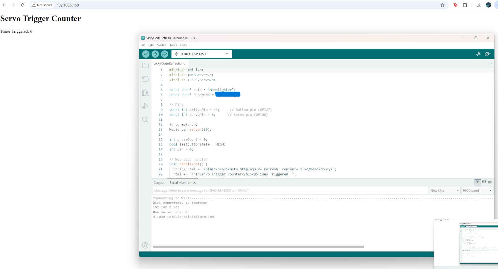
- Currently I have my ESP32s3 functioning, connecting to the internet and providing and IP address to the basic site that displays a counter for every time the switch is triggered. Only the site does not display the number count in really time. I have to refresh the page and even when doing so, it doesn’t seem to be the most accurate.
- With Peter’s assistance, we asked chat gpt how to make my site auto refresh every time the switch is clicked. It initially suggested to use JavaScript, add a new route for the counter value and a new endpoint. This is where Peter’s experience was helpful since he knew there were additional, simpler ways to achieving the same goal without having to dive into JavaScript. When asking Chat how to do meta refresh, it provided a very simple, one line solution, which is what I used to complete my networking and communications goal.
To see the full Chat GPT conversation, click on this LINK
- Now my board transfers the data of when the switch is clicked to the website in real time (with a delay but still works), displaying the number of times it has been triggered.

Group Assignment
We connected two microcontrollers wired to a computer using said computer as an intermediary. One microcontroller had an input device sending a signal to the computer which was then received by the second microntroller affecting an output. We finalized this assignment with the help of ChatGPT.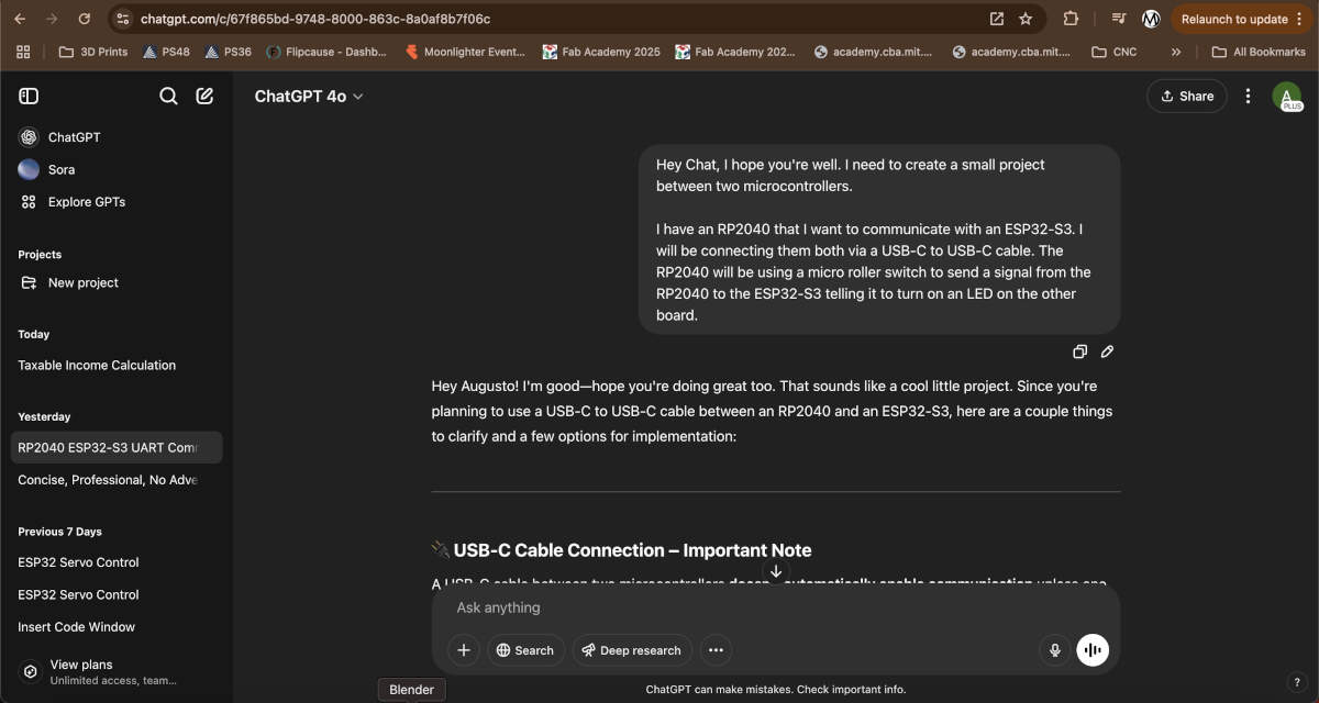
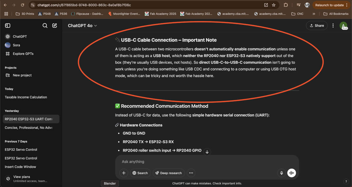
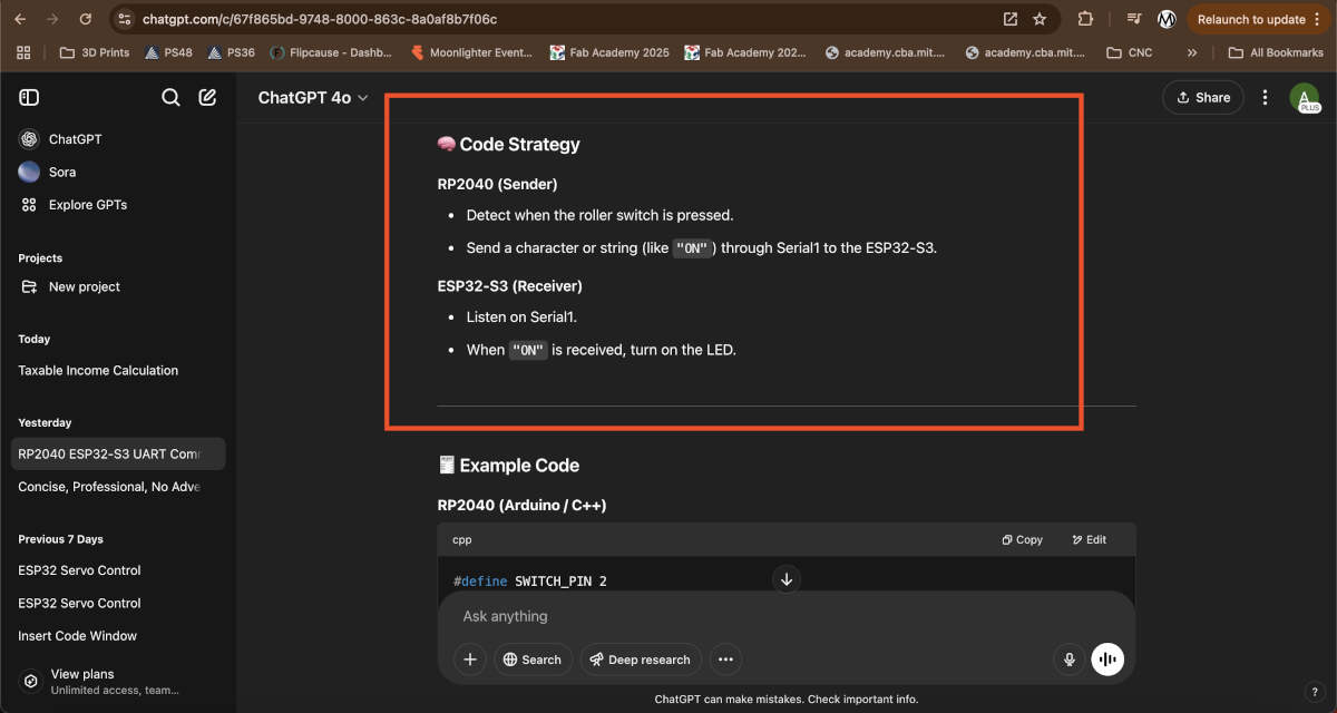
ChatGPT clarified that connnection of these two boards solely by a USB-C to USB-C cable would not work. It did understand that the signal sender would be the RP2040 and the receiver would be the ESP32-S3. We received some sample code from Chat, but we couldn't make proper use of it because of our connection issue.
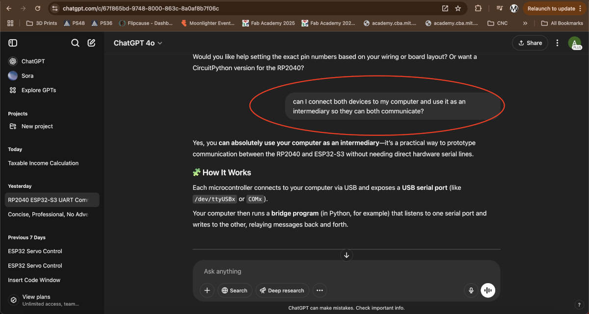
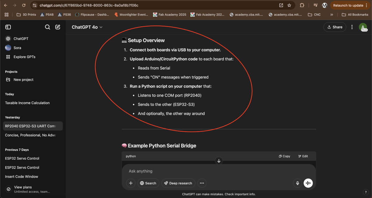
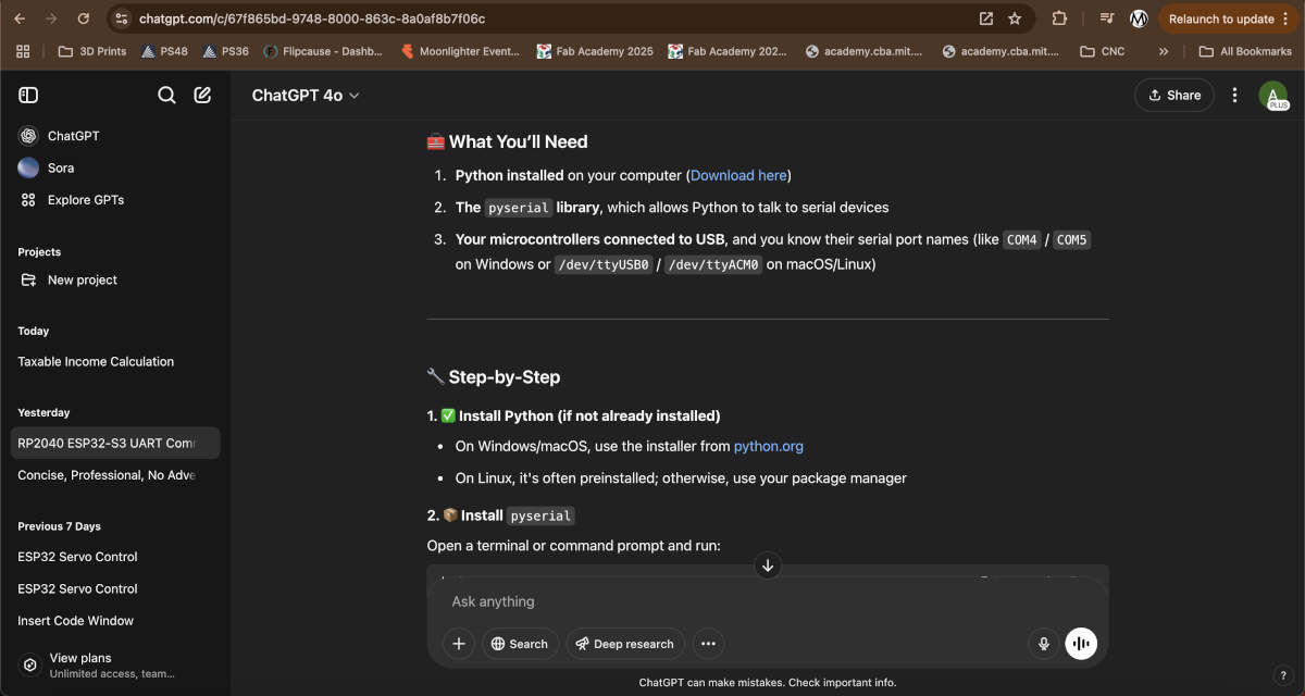
To make up for the fact that we did not have the capabiliies to connect both via USB-C, we asked ChatGPT if we could bridge both devices using a computer. ChatGPT confirmed we could. We had to ensure to connect both boards to a computer, in this case, we chose Vicky's PC due to her having multiple ports compatible with USB-C and USB-A. We uploaded the sender/receiver codes and updated the pins on the RP2040 and ESP32-S3, respectively. We set about installing Python on Vicky's computer. Next we had to install the Pyserial library which allows Python to communicate to serial devices. This was unfortunately a roadblock because we had to first install PIP, which is a pacakge manager that can install libraries and packages for Python. This was resolved by using this video as reference -
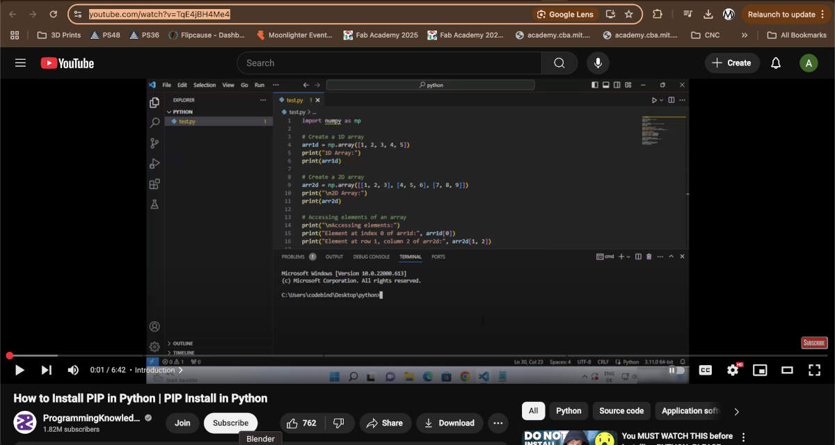
How to Install PIP in Python | PIP Install in Python
This video clarified the installation process for PIP, which involved using this command - curl https://bootstrap.pypa.io/get-pip.py -o get-pip.py
Then this command -
python get-pip.py
Once this is finalized the command prompt or terminal you used will give you the address where PIP was installed. Copy this address, head to System Properties, go to Environment Variables, click on the Path variable located under System Variables, edit the Path variable, and paste the new path/address you copied earlier. Once this path is pasted, hit "OK" on all windows. Then please make sure to close your terminal to properly finalize the install. Open your chosen terminal once more and type "pip --version" to verify what version is installed.
This simplifies the install for Pyserial. It allows you to simply input "pip install pyserial" into Command Prompt or any other terminal
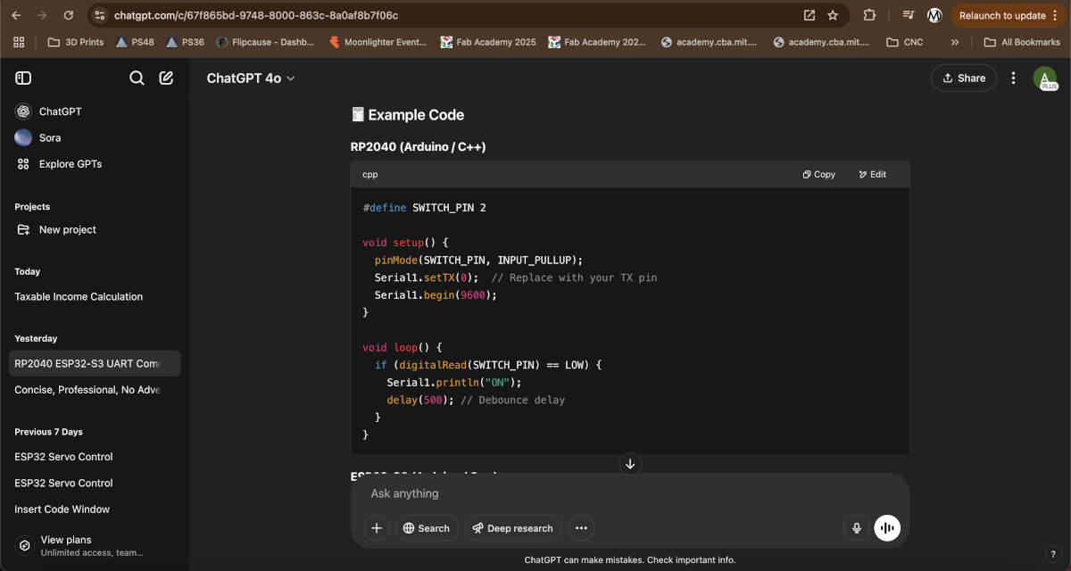
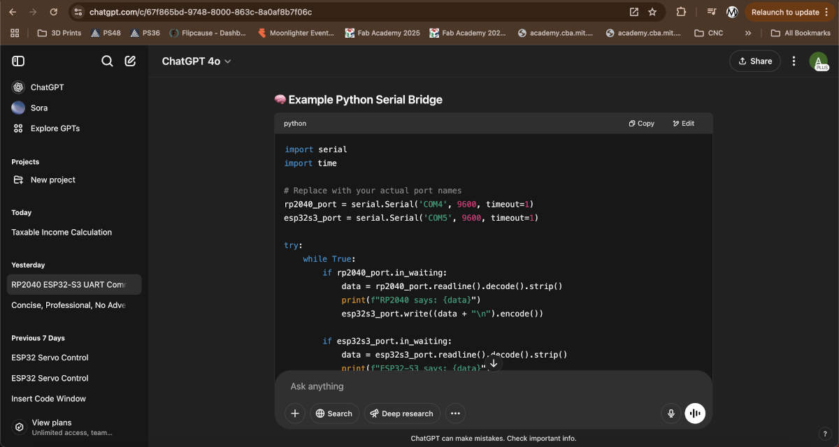
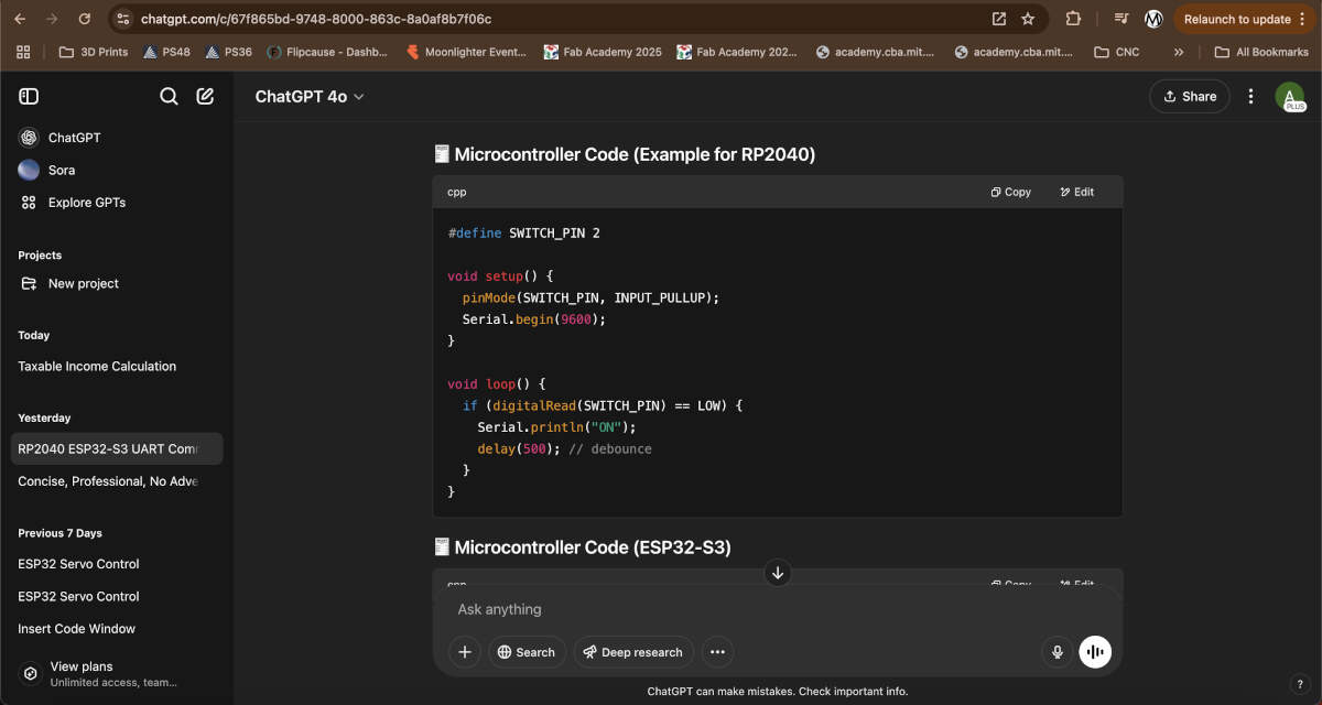
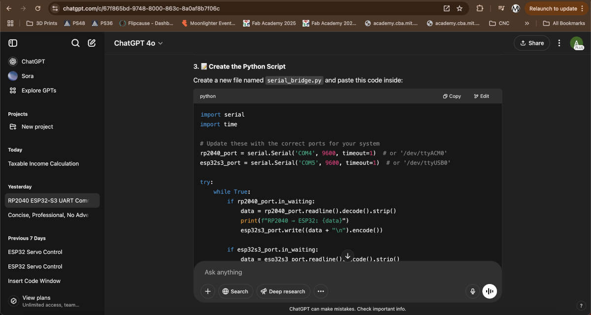
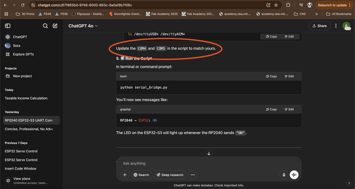
The next step is to use a notepad app to create a file named "serial_bridge.py" and paste the code in image/slide 8. We updated the COM ports in the script to match COM5 and COM7 where our boards were plugged into. Below you'll see all three pieces of code to run this. You'll see the sender code we uploaded to the RP2040, the receiver code uploaded to the ESP32-S3, and the serial bridge that will be run in any terminal or command prompt.
rp2040_switch_sender.ino
#define SWITCH_PIN 2
void setup() {
pinMode(SWITCH_PIN, INPUT_PULLUP);
Serial.begin(9600);
}
void loop() {
if (digitalRead(SWITCH_PIN) == LOW) {
Serial.println("ON");
delay(500); // debounce
}
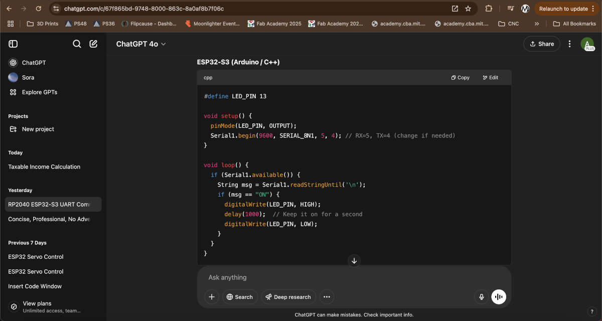
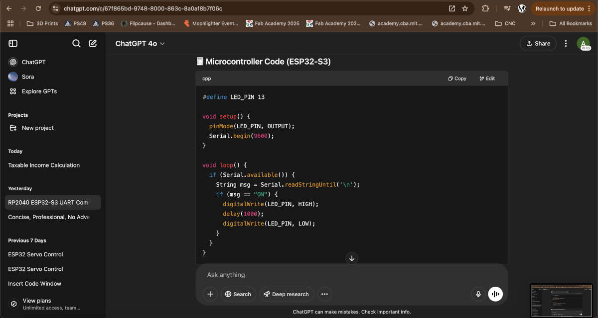
}esp32-s3_LED_receiver.ino
#define LED_PIN 13
void setup() {
pinMode(LED_PIN, OUTPUT);
Serial.begin(9600);
}
void loop() {
if (Serial.available()) {
String msg = Serial.readStringUntil('\n');
if (msg == "ON") {
digitalWrite(LED_PIN, HIGH);
delay(1000);
digitalWrite(LED_PIN, LOW);
}
}
}serial_bridge.py
import serial
import time
# Update these with the correct ports for your system
rp2040_port = serial.Serial('COM4', 9600, timeout=1) # or '/dev/ttyACM0'
esp32s3_port = serial.Serial('COM5', 9600, timeout=1) # or '/dev/ttyUSB0'
try:
while True:
if rp2040_port.in_waiting:
data = rp2040_port.readline().decode().strip()
print(f"RP2040 → ESP32: {data}")
esp32s3_port.write((data + "\n").encode())
if esp32s3_port.in_waiting:
data = esp32s3_port.readline().decode().strip()
print(f"ESP32 → RP2040: {data}")
rp2040_port.write((data + "\n").encode())
time.sleep(0.01)
except KeyboardInterrupt:
print("\nClosing ports...")
rp2040_port.close()
esp32s3_port.close()When ready, run the following python script in command prompt or terminal of choice - python serial_bridge.py
After this, the sending signal will light up the LED on the other board. In our case Vicky's RP2040 is the sending signal using a rolling switch to activate the signal. Augusto's ESP32-S3 is the receiving signal which lights up one of the LED's on his board when active.